In the game of soccer, an individual player must run fast, think fast, and be agile ... fast response to external events, and can maintain (or regain) body attitude's ...
Team KMUTT: Team Description Paper Pasan Kulvanit, Bantoon Srisuwan, Khunit Siramee, Apinya Boonprakob, and Djitt Laowattana King Mongkut’s University of Technology Thonburi, Institute of Field Robotics (FIBO) 91 Pracha u-tid Rd., Bangmod, Thungkru, Bangkok 10140, Thailand {pasan, bantoon, khunit, nung_1, djitt}@fibo.kmutt.ac.th http://fibo.kmutt.ac.th
Abstract. This paper explains the scientific achievement of our Robocup Humanoid league team. We are able to transfer our knowledge into the robot hardware that will be used in the humanoid robot soccer game. With the current robot design, the robot can achieve two walking mode- static walk and dynamic walk. The static walk mode will be used when locomotion precision is needed. The dynamic walk will be used when fast speed is needed. We implement simple vision based navigational scheme inside low cost vision system hardware. Our two-legged robot can autonomously traverse the game field while recognizing the target (colored ball) and environment (opponents and/or the obstacles) and execute the actions according to plan.
1 Introduction In the game of soccer, an individual player must run fast, think fast, and be agile in order to gain advantage over the other players. Teamwork is also a must for the team to win the game. There is no difference for the humanoid robot players. The robot system for the Robocup’s Humanoid league competition must have fast computing, fast response to external events, and can maintain (or regain) body attitude’s stability robustness through out the game. All the devices that used to realize the above requirements have to fit in a small package. As mention in [6] and [7], we can divide the issues that the biped needs to meet into three parts - the mechanical design, the computing hardware/control implementation, and the software. The weight of mechanical structure of the biped must be light. The actuator must output the highest power at the smallest expense of the actuator weight. The controller must be simple in order to reduce the processor memory storage and computational time. The implementation of the controller software must be in the environment of Real-Time operating system, such that, the response to the external event can be done in the deterministic boundary. This is not to mention the computing hardware must be as simple and as user-friendly as possible. The software code that is used to control the system must be smart enough to recognize the dynamic event and can issue action to counter such event. We based our humanoid robot systems on these three crucial issues. Team KMUTT will participate in the Robocup 2006 Humanoid league. The final rule draft of the 2006 humanoid league can be consulted in [1]. Pertinent to this year rule, we focus our research and development on two issues – the biped locomotion
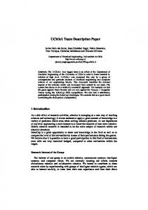
and vision based navigation. On the biped locomotion issue, we divide the mode of interested locomotion into statically stable walk and dynamically stable walk. Our robot in the previous year [5] utilized mainly the static walk mode. With the static walk, while the robot can maintain the stability quite well during walking, it cannot move quickly enough to accomplish tasks in specified time in such event as Penalty kick or long-distance obstacle walk. The speed issue manifests itself even clearer in the demonstration match against the AIBO robot dog. The robot dog shows superiority in term of speed. It is clear that if the humanoid robot wants to perform well in the robot soccer game, it needs robust dynamic walking scheme. Certain team shows good result in dynamic fast walking with help from 3 rate gyro sensors [3]. On the vision based navigation issue, the problem from previous year is mainly the sensitivity of the camera to the change of ambient light. Since our range detection scheme depends on thresholding, the camera sensitivity to light effects the range calculation greatly. The other important issue to be solved is robot localization. How can the robot know at all time where it is on the game field with respect to other important targets such as opponent’s goal, own goal, ball, field markers, same side’s robot, and opponent’s robot? Some teams solve this issue using omni-directional camera [9]. Some installed forward and backward camera at the head [8]. Some even ignore the camera and seek the advantage of 360 sweep of sonar sensor [2]. With all the issues raised up, we also have to keep in mind that all results must be able to be implemented efficiently and economically inside a small package such as a small size humanoid robot. Figure 1 shows the two robots from Team KMUTT that will enter the Robocup 2006 Humanoid league competition. Details specification can be found at http://fibo.kmutt.ac.th
Fig. 1. Jaidee [left] and Jeed [right]. The height is approximately 45 cm
In this paper, we will describe our humanoid robot systems that will be used in the competition. The main focus of this paper is on the theory behind the locomotion schemes and the underlying method of the vision based navigation that will be used on-board our humanoid robots. Section 2 shows the competition-ready system overview. Section 3 addresses the locomotion schemes. Section 4 demonstrates our idea of low cost vision based navigation. Section 5 concludes the paper.
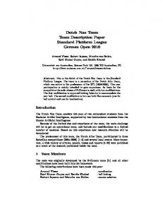
1 System overview This section explains the hardware used in our biped robots. Each robot is composed of mechanical hardware, sensors, and computing hardware. Figure 2 shows the overall systems. Mechanical hardware is composed of robot structure and motor. The structure of both robots is made from aluminum alloy sheet metal in order to keep the weight low while benefiting from the high strength property. The two robots use different kinds of motors. Jaidee uses the RC-servo motor (pulse coded control), while Jeed uses RS-485 networked servomotor. Both robots contain 22 degrees of freedom. Both robots use the same set of sensors. These are 2-axis accelerometer [+/-2g], 2 rate gyros [+/-100 deg/sec], 8 force-sensing resistors, and one camera. The accelerometer tells the robot if there is any longitudinal and/or transversal tilt. The two rate gyros measure angular velocity at longitudinal and transversal axis. The angular velocity information will be used to adapt the attitude of the body during walking. The force sensing resistors are used to sense the vertical ground reaction force. Force information will be used to adapt the attitude of the body during static walk. The camera is used to track the ball and other objects of interest, which is crucial for navigation decision-making software.
Fig. 2. System overview of the humanoid robots [Jaidee and Jeed]
The main computer for both robots is ARM-7 [60MHz] RISC microprocessor. Its major function is to make decision based on the information obtained from the camera system and sensors. The main computer, then, issues commands to the other ARM-7 processor to generate walking paths. The inverse kinematics of the robot legs and the pre-programmed (such as self-righting gait, walking straight, turning in place, circular gait, etc.) gaits are stored in ARM-7 motor controller. The robot can choose to execute the pre-programmed gait or adaptable gait such as gyro-assisted fast walk gait. In the case of Jaidee, the DSPic will subsequently processes generated paths in order to command each of the RC-servo motors with PWM command. In the case of Jeed, the generated paths will be sent directly to servomotors via RS-485 network.
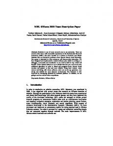
3 Locomotion schemes Bipedal locomotion is the main mode of locomotion for robots in this class of Robocup competition. The task of coordinating movements of multiple actuators in order to create the desired walking pattern is not trivial. Not only the kinematics of the robot has to be well understood, the dynamic effect during the locomotion is also very crucial for robust walking scheme. Our goal here is to construct gaits that contain the following characters. Firstly, the foot must be lifted up from the ground completely during motion. This is because the gait that utilizes sliding or slipping motion can be disturbed by excessive external force from the ground and affects robot positioning of the foot and body. Lifting a foot is also good for traversing an uneven terrain such as the rough terrain challenge. Secondly, the gait cycle must be as short as possible. This is because the short cycle gait results in a higher speed walk than the long cycle gait. A high-speed movement is crucial in the game of robot soccer. Furthermore, the short cycle gait saves battery consumption and servomotor’s operating life. Note that extended period of torque holding time heats up the motor’s coil and reduces the life of the motor and results in excessive battery energy consumption. There are two modes of locomotion schemes used by our team – the static walk and the dynamic walk. The proof of statically stable walk and methodology can be found in [4,5]. We are here to discuss dynamically stable walking scheme. 3.1 Control Design The objective of the controllers is to regulate the hip height and the horizontal velocity of the hip. We model our system as an inverted pendulum with variable leg length with force source in the leg structure that can exert a limited amount of force to extend the CM’s position in the radial direction. The torque at the ankle is available in this case. Note that if the ankle torque becomes zero, the system becomes a passive dynamic one. We also assume no-slip condition at the contact between the foot and the ground. Based on the model displayed in figure 3, (1) and (2) shows the equations of motion for our nonlinear system.
Fig. 3. Inverted pendulum with variable leg length used in dynamic walk analysis
Tq r 2θ&& + 2rr&θ& − gr sin θ = m
(1)
F &r& − θ& 2 r + g cos θ = m
(2)
Next, we want to design a controller to regulate the hip height and the horizontal velocity during traversing. Naturally, we pick hip height and horizontal velocity as our controlled variables. For horizontal velocity regulation, the horizontal velocity expression is given in (3). We would like the deviation from the set point becomes zero, i.e., (4) approach zero in the shortest time.
v h = rθ& cos θ + r& sin θ
(3)
errt = v hset − v h
(4)
The PD controller can be constructed as shown in (5). We utilize the torque input to control the horizontal velocity.
Tq = k1t (errt ) + k 2t
d (errt ) dt
(5)
We also want the biped robot to traverse the terrain with constant hip height. The hip height is defined in (6). We would like the deviation from the set point becomes zero, i.e., (7) approach zero in the shortest time.
h = r cos θ
(6)
err = hset − h
(7)
The other PD controller can be constructed as shown in (8). We utilize the force input to control the hip height.
F = k1 (err ) + k 2
d (err ) dt
Nomenclatures r : Leg length θ : Angle between the vertical line and the leg g : Gravity
Tq F v hset vh
: Control torque applied at the ankle : Control force applied at the knee : Hip horizontal velocity set point : Hip horizontal velocity
(8)
errt : Hip horizontal velocity error k1t : Proportional gain for hip horizontal velocity control k 2t : Derivative gain for hip height velocity control hset : Hip height set point h : Hip height err : Hip height error k1 : Proportional gain for hip height control k 2 : Derivative gain for hip height control 3.2 Simulation results MATLAB is used to solve the initial value problem. (1) - (8) are used in the numerical integration process for the non-linear dynamical system. The mass of the robot is 3[kg]. The initial values for the integration are r0 = 0.2 [m], and r&0 =
θ 0 = -pi/8, θ&0 = 2 [rad/s],
θ&0 [m/s]. Note that the initial velocity of the CM is in the horizon cos θ 0 r0 sin θ 0
tal direction.
CM traveling direction
Set points:
hset = 0.2 sin
pi 10
v hset = 0.4 [m/s]
Fig. 4. Inverted pendulum model traveling from left to right under the hip height and the CM’s horizontal velocity regulation. All axes have unit in [m.]
Fig. 5. Horizontal velocity of the CM is regulated at 0.4[rad/s]
Fig. 6. Vertical velocity components from linear motion and rotational motion. The equality of the two components means the CM keeps constant altitude
Note on figure 6. Since we have two sources of input – ankle torque input and leg force input, there are also two components of vertical velocity that can affect the altitude of the CM. (9) and (10) define the two components.
vv _ lin = r& cos θ
(9)
vv _ rot = rθ& sin θ
(10)
Where, v v _ lin is the vertical velocity component from the linear motion (due to force input) and vv _ rot is the vertical velocity component from rotational motion (due to ankle torque input.) We need these two vertical velocity components to be equal at all time in order to have constant CM’s altitude.
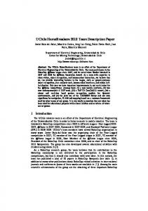
Fig. 7. Torque input during the course.
From figure7, note that the torque input starts at positive 2 [N-m] and coasting down to –2 [N-m]. This is because the CM is propelled forward by the torque output in the first half of the trajectory. The minus torque output means that the counter torque occurs in order to keep the horizontal velocity in-check at the set point. The range of the torque input magnitude from 2 to –2 [N-m] is realizable with the current set of motor.
4 Vision based navigation 4.1 Object locating scheme The purpose of the object-locating scheme is to find the angular position and the distance of an interested object from the robot. Once this information is obtained, the robot can decide whether to approach the acquired target (in case of a ball) or avoid the target (in case of an obstacle).
Fig. 8. Pan-tilt mechanism used on-board the humanoid robot
We use the single lens CCD camera mounting on the pan-tilt mechanism to obtain the location of the targeted object. Note that the pan-tilt mechanism is mounted at the head of the humanoid robot. The pan feature of the mechanism can rotate from zero (leftmost) to 120 degrees (rightmost). The field of view (FOV) of the camera is 40 degrees. If we want to get the 120 degrees panoramic view with this camera we need to pan the camera to three positions – 20, 60, and 100 degrees with respect to the pan motor frame. If the robot wants to check the location of the target, the pan-tilt mechanism must pan three layers of the windows in the order labeled in table 1. Table 1. Pan layers of the camera and all the windows
1 20° 4 20°
2 60° 5 60° 7 60°
3 100° 6 100°
The first row of pan signifies the panoramic view far away from the robot. The third row shows the view closest to the robot. Since the degree of freedom of the pantilt mechanism is limited, only the 60-degree camera position is realized for the third row. The resolution of the CCD camera is 80 horizontal X 143 vertical pixels. Figure 9 shows the top view of the pan action used to detect the angular position of the target with respect to the current robot’s heading. If we want to find the robot heading with respect to the location of the object in question, we can calculate the angular value by identifying the value of the horizontal pixel of the centroid of the color blob then we can compare this value with the known conversion. In this case, we know that 80 pixels span 40 degrees. For example, assume that the camera is locked at window number four (from table 1) and the color blob’s centroid is at horizontal pixel-X, hence, the object is at the angle of (40/80)*X measuring from the zero-degree line of window number four. The robot heading is, therefore, 60-20-(40/80)*X.
Fig. 9. Determination of robot heading toward the targeted object [Top View]
After the robot is lined up correctly with the target, we need to find the distance from the robot to the target. Initially we need to calibrate the camera to obtain the relationship between the tilt angles and the continuity of the camera frame. As shown in figure 10, we divide the tilt actions into three windows such that the robot can detect the distance from zero to 150 cm.
Fig. 10. Determination of the distance from the robot to the target object [Side View]
We initially calibrate the camera to find the relationship between the tilt angles and the distance from robot to the object. The calibration results are shown in table 2. Note that frame 1,3,4,and 6 are not used in the case of finding distance. Note also that each frame of the camera contains 143 vertical pixels. We can then compare the de-
tected pixel value (in figure 10, this is Pixel_Y) with the known conversion obtained from the calibration. Table 2. Tilt layers of the camera and all the windows
1 4
2 34cm to 150cm 5 17cm to 34cm 7 zero to 17cm
3 6
4.2 Navigation decision-making scheme The angular position and the distance of the targeted object obtained previously will be used as an input into the decision-making algorithm. The targets for this algorithm are ball and goal. The final action is such that the robot finds the ball and kicks the ball accurately toward the goal. Through out the process, there is also a fall detection loop to check if the robot is standing straight up or already falling down. If such a case happens, the self-right mechanism will be called. Once the robot stands straight again, the same routine continues.
Fig. 11. Diagram shows navigation decision-making scheme
Step 1: Pan the camera to find the angular position of the ball with respect to the current heading of the robot. Turn the robot body to face the ball. Step 2: Walk forward to the specified distance. Step 3: Pan the camera to find the angular position of the target with respect to the current heading of the robot. Execute “circular gait”, i.e., sliding in circular direction with body facing the ball at all time. Step 4: Walk forward to the specified distance to kick the ball.
Step 5: Kick the ball toward goal. Although the validity of the above algorithm is proven by good performance displayed by the robot, further improvement can be made, especially, range finding scheme. Instead of counting the pixels and compare with the pre-calibrated value, we may be able to use simple trigonometry to calculate the distance using only tilt angle of the camera and the known distance such as the height of the robot. This method is free from the ambience light affect and may give a better estimation of the distance from the target to the robot.
5 Conclusions We have designed and built a complete humanoid robot system that can autonomously recognize the environment and execute the task of kicking ball and navigating the game field. The robot relies on two modes of locomotion- static walk to achieve high stability robustness and dynamic walk for fast speed traverse. The dynamic walking scheme is highlighted in this paper. The camera system is used to seek the ball and goal. The range information of game objects will be used in the decisionmaking process. The main computer generates command to control all motors to execute the ultimate action based on the final decision.
Acknowledgements Team KMUTT and the Institute of Field Robotics (FIBO) would like to thanks Asian Honda Motor Co., Ltd., Advanced Info Service Plc., and Unocal for their supports.
References 1 Behnke, S.: Robocup soccer humanoid league rules and setup for the 2006 competition in Bremen, Germany (2006) 2 http://www.geocities.jp/toinphoenix/index.html 3 http://www.hajimerobot.co.jp/robot/hajimerobot15.htm 4 Ito, S., Asano, H., and Kawasaki, H.: A Balance Control in Biped Double Support Phase Based on Center of Pressure of Ground Reaction Forces, IFAC Symposium on Robot Control (2003) 5 Kulvanit, P., et al.: Team KMUTT, Team description paper. Robocup 2005, Humanoid League (2005) 6 Kulvanit, P. and Laowattana, D.: Crucial Issues for Biped Mechanism in Achieving Dynamically Stable Legged Locomotion, MENETT Annual Meeting (2003) 7 Kulvanit, P. and Laowattana, D.: Dynamic Stability and Mobility of a Small-sized Biped Mechanism, Asia International Symposium on Mechatronics (2004) 8 http://www.NimbRo.net 9 Yamato, N., et al.: Team Osaka, Team description paper. Robocup 2005, Humanoid League (2005)