@ URI
TEAPC: Adaptive Computing and Underclocking in a Real PC MuRI Technical Report No. 20041027-1 Augustus K. Uht and Richard J. Vaccaro Dept. of Electrical and Computer Engineering University of Rhode Island Kingston, RI, USA 02881-0805 October 27, 2004
Abstract TEAPC is an IBM/Intel-standard PC realization of the TEAtime performance “maximizing” adaptive computing algorithm, giving performance beyond worstcase-specifications. TEAPC goes beyond the TEAtime algorithm by adapting to the current CPU load. It is also the first machine to use extensive underclocking for disaster tolerance, low power consumption and high reliability. This is all done dynamically, at runtime, on an unmodified standard operating system (Windows 2000) with a purely software-implemented feedback-control based algorithm.
Copyright © 2004 A. K. Uht and R. J. Vaccaro
TEAPC: Adaptive Computing and Underclocking in a Real PC Augustus K. Uht and Richard J. Vaccaro University of Rhode Island Microarchitecture Research Institute Department of Electrical and Computer Engineering 4 East Alumni Ave. Kingston, RI 02864, USA {
[email protected],
[email protected]}
Abstract TEAPC is an IBM/Intel-standard PC realization of the TEAtime performance “maximizing” adaptive computing algorithm, giving performance beyond worst-case-specifications. TEAPC goes beyond the TEAtime algorithm by adapting to the current CPU load. It is also the first machine to use extensive underclocking for disaster tolerance, low power consumption and high reliability. This is all done dynamically, at runtime, on an unmodified standard operating system (Windows 2000) with a purely software-implemented feedback-control based algorithm.
1 Introduction Adaptive systems “maximize” performance or “minimize” power consumption with respect to changes in environmental, operating and manufacturing conditions. Underclocking reduces the operating frequency below that normally specified, reducing power consumption and increasing reliability. In this paper we present a prototype based on the standard IBM/Intel PC architecture realizing both adaptive computing and underclocking. In other work an adaptive system called TEAtime [13] was demonstrated by Uht with a simple physical prototype (see Section 2). We wanted to fully demonstrate TEAtime’s potential by putting it in a production microprocessor, but that is problematic. We therefore did the next best thing: demonstrating TEAtime’s adaptive attributes on a real PC assembled with COTS (Commercial Off-The-Shelf) parts. TEAPC, the resulting prototype, goes further than TEAtime: It adapts to current CPU computational loading, and greatly underclocks for disaster tolerance and low power, while still functioning normally. The initial TEAPC implementation used timingbased sensors, similar to that used in the TEAtime prototype. For reasons to be discussed later, this was
abandoned in favor of basing the real-time performance or frequency of the CPU on the CPU’s real-time internal temperature. Since this is the major component of variation of timing within an Intel microprocessor (the CPU’s core voltage is highly regulated and approximately constant), it mirrors the original TEAtime philosophy. Further, it is possible to base the real-time performance on the real-time power consumption of the entire PC; the latter is partially addressed in this paper. We have implemented the entire control system in software, in a Windows application. It runs in a normal application mode on Windows 2000, multitasking normally with other applications. CPU frequency and core voltage are changed dynamically, based on the output of a feedback control system using the CPU chip temperature as its primary input. While details such as specific hardware device addresses may change, the basic approach and detailed realization of the control loop and underclocking should be implementable on any PC to be built, as well as many that already exist. Summarizing, our goals are: TEAPC should have the adaptation and frequency maximization properties of TEAtime; additionally, TEAPC should realize adaptation to varying CPU loads, low power consumption and high reliability on-demand, and disaster tolerance. All of these goals have been realized with the aid of a purely software-based feedback control system, employing CPU frequency underclocking as needed. The rest of the paper is organized as follows. Section 2 discusses prior work and background information. Section 3 describes the initial TEAPC solution and real system constraints. In Section 4 TEAPC’s final version is discussed, along with the experimental methodology. Section 5 presents the experiments, data, and analyses. Examples of different TEAPC operating scenarios are given in Section 6. We conclude in Section 7.
page 1 of 12
2 Prior Work Performance- and power- adaptive computing approaches have only been proposed in the last decade or so. Most techniques are mainly concerned with power reduction [1, 4, 5], while a few recent methods consider performance enhancement [6, 8]. Most methods use voltage-scaling for powerreduction. The recent Razor proposal [2] and the earlier TIMERRTOL model [11] are unusual in that timing errors are not avoided, but rather are used as a feedback mechanism to regulate either power consumption (Razor) or performance (TIMERRTOL). They employ different methods to recover from the timing errors. One of the key observations that can be made about all of this adaptive computing work is that in general the same basic mechanism can be used for either power reduction or performance enhancement (or both). These methods achieve better-than-worst-case performance or power consumption. Skadron et al [9] first considered the use of formal feedback control theory as applied to the on-chip control of chip temperature of a microprocessor. Instruction fetch toggling was used to control the chip temperature. In [10] on-chip frequency-scaling was used to regulate the chip temperature using a simple linear relationship between frequency and temperature; formal control theory was not needed since the relevant thermal delays and changes in frequency and temperature were small. Slowdown was also small. Reliability could not be enhanced. In TEAPC, performance can be increased with the particular methods used, and at the system level, without chip modification. Should reliability be an issue, TEAPC can instead enhance that. Rohou and Smith [7] used operating-system based software to control the temperature of a chip in a system via frequency scaling; performance only decreases, never increases. The frequency control mechanism puts the CPU in either a doze state or a full operation state; however, TEAPC utilizes sophisticated feedback control for adjustment of frequency, temperature and reliability, executing all code normally, all of the time. Also, TEAPC does not require operating system modifications, and can increase performance.
operation, the tracking logic is fed a never-ending stream of alternating one’s and zero’s. The operating frequency of the system is incrementally increased until an error occurs in the output of the tracking logic; at this point the frequency is decreased until the error ceases, and then the process repeats. Since the tracking logic is guaranteed by design to be slower than any other path in the system, any timing error will occur in the tracking logic first, and only there. Hence, timing errors in the main system are completely avoided. This also completely avoids added pipeline stalls or other additional clock cycles. Throughput increases of almost a factor of two were demonstrated in a physical TEAtime prototype. TEAtime adapted to changes in the environment (e.g., temperature), operating conditions (e.g., supply voltage) and manufacturing conditions (e.g., quality of a given production run), dynamically “maximizing” performance While the TEAtime prototype demonstrated the basic worth and functionality of the TEAtime idea, it used a very simple home-brew processor implemented on an FPGA. In our desire to extend the TEAtime ideas and applications, we decided to implement and evaluate TEAtime on a real PC, using COTS parts. We have created a high-performance feedbackcontrol system using normal application software, not requiring any operating system modifications. Disaster tolerance is achieved, and reduced power consumption and increased reliability may be userspecified. TEAPC is the result.
3 Initial TEAPC Architecture and Control System 3.1 Foundations of TEAPC The guiding principle in the design of TEAPC was to use as much COTS hardware and software as possible. To this end, TEAPC’s foundation is a standard IBM/Intel PC architecture assembled out of COTS parts. (A commercial PC was not considered, since it would be unlikely to allow the kind of internal access we required. However, the results of this work can easily be applied to commercial PC’s, during their design, construction and/or testing.)
We wished to be conservative in our results, so assembled TEAPC out of harder-to-control high-end parts (at the time): a 3.0 Ghz Intel Pentium 4 microprocessor with an 800 MHz bus and an Intel 875P chipset (a “chipset” is the glue logic that connects the CPU to the main memory and I/O devices; in Figure 4 it is the Northbridge/Southbridge pair of chips). The main memory used high speed DDR (Dual Data Rate) dynamic RAM. page 2 of 12
Uht’s TEAtime (Timing Error Avoidance) system [12-14], approximated a maximization of performance much above that normally allowed by standard design practices. The key component was tracking logic, a one-bit wide copy of the worst-casedelay path between any pair of flip-flops in the digital system, plus a small safety margin delay. In
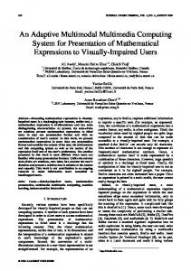
3.2 Initial Approach Towards a TEAPC Prototype Our initial plan and activities were to closely model TEAPC operation on that of the TEAtime prototype. While we were of course unable to embed tracking logic in the existing components, especially the CPU, we were still able to create tracking sensors whose delay varied with temperature, supply voltage, etc. While we did not fully validate the following, since each sensor was a standard CMOS logic gate integrated circuit we felt the sensor would to a large degree mirror the sensitivity of the internal logic of the parts to be monitored. We monitored four components on the PC’s motherboard: the CPU, the Northbridge and the two main memory modules. The sensors were 4-gate surface-mount IC’s with 50 mil (thousandths of an inch) pitch leads. Each sensor was thermally-coupled to its component by fixing the top (non-lead) side of the sensor to the component with thermal grease or thermal tape between the two. In reality, to avoid complex machining, each sensor was attached to the heat sink of its component, as close as possible to the component itself. Each sensor’s gates were wired in series at the sensor, with an input, an output and power connections brought out on four 30 gauge wires to an added FPGA. The FPGA contained counters and other control circuitry to measure the delay through each sensor. The FPGA in turn connected to TEAPC itself through TEAPC’s parallel port. The teapc program received the digitized delays, and used them as inputs to the TEAPC control algorithm. The control algorithm uses the CPU’s frequency as the algorithm’s dependent output. Every component’s temperature is dependent on the component’s power dissipation, and the latter is roughly proportional to the component’s operating frequency. Since each of the components’ clocks has roughly the same frequency as the CPU’s clock, they all heat up at roughly the same time. This in turn heats the sensors, increasing their delay, and the feedback loop is complete; see Figure 1.
3.3 The Feedback Control System Hope springing eternal, the first attempt at a control system was to use essentially the same one as in the original TEAtime prototype: a zero-delay feedback system incrementally increasing or decreasing the frequency (Note: from now on, ‘frequency’ refers to the CPU’s frequency, which indirectly controls the rest of the components’ frequencies.) The classical
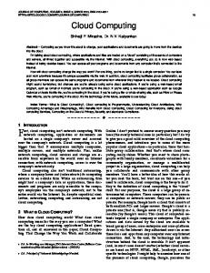
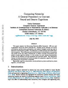
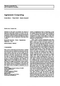
method worked poorly, often giving large frequency oscillations, all the way from hard lower to upper limits and back, and slow response. The main reason for the inadequacy of this simplistic approach is the thermal capacitance of the components’ heatsinks, with the resulting roughly exponential time delay between component heating and sensor response. We then used formal feedback control system theory to eventually achieve a fast frequency response to thermal changes. The basic control input is a temperature setting, Tset, used by the control system to maintain a CPU temperature of Tset degrees C. Tset would typically be made equal to a temperature just above the maximum CPU frequency under full load, so as to maximize performance. However, should the user desire to save power or increase the reliability of the CPU Tset can be reduced. The original system had four feedback loops (see Figure 1), one per sensed component, and only one dependent control variable, the frequency. The system still oscillated greatly. This is because the system is formally uncontrollable: Its controllability matrix is not full rank. Physically, two similar feedback loops cannot be independently controlled of the other (similar) pair since they have the same input. Since the only component near to overheating was the CPU, the other three sensors were removed from the control system. We verified the safety of the other components only after monitoring the temperature of each of them under many conditions, using a thermocouple placed next to each sensor. The control system went through several single-pole design iterations, an example of which is shown in Figure 2. While the frequency oscillations were reduced, the system still responded slowly. Our current solution to the control system design problem completely eliminated the external sensor system, instead relying on the internal temperature of the CPU for the only input to the system. This sped up the system considerably. Second, the final system was designed with state-of-the-art discrete-time techniques as an integral control system using statespace methods [3, 15]. The system was modeled from measured input/output data using the System Identification Toolbox (from the Mathworks). The Toolbox returned a second-order model, and this was approximated with a first-order system model. The latter is shown in Figure 3. This system has excellent response characteristics, having a frequency settling time of only about 10 seconds for a Tset change equivalent to a change in frequency from 2.5 GHz to 3.5 GHz of the CPU under full load.
page 3 of 12
∆K ∆sens ∆sens ∆N N 273.15 K + + KsT KNs 1 Tset ( C) KG s sens/ K N/sens ¯
¯
KfN freq/N
¯
¯
Component, Heatsink, and Sensor + K ¯
¯
+
KTs K/sens
Ksf s+A
CPU
KTs
sens
Ksf s +A
Northbridge
sens
Ksf s +A
Memory Module A
sens
Ksf s +A
Memory Module B
¯
K/sens
¯
+ K ¯
KTs K/sens
¯
+
freq (Hz)
sens
+ K +
Clock Synthesizer
+ K ¯
KTs K/sens
¯
Figure 1. First formal feedback control system tried. Each of four sensors has its own feedback path.
Clock Synthesizer and CPU 273.15 K freq ∆K ∆sens ∆sens ∆N N sens K (Hz) + Tset ( C) + KsT KNs KfN KTs Ksf 1 KG s s +A sens/ K N/sens freq/N K/sens 0.5939 11.9317e6 1/27.05 23.09 ¯
¯
¯
¯
¯
¯
A=0.01526 Figure 2. Single sensor, single feedback path control system.
Clock Synthesizer, CPU and CPU internal sensor ∆K
∆N
¯
Tset ( C) + ¯
KNT N/ K
KG
17.4
0.28
¯
-
∆N
N 1 + s -
KfN freq/N 8.26e6
KFA 70.0
Figure 3. Final TEAPC feedback control system.
page 4 of 12
freq (Hz)
freq (Hz)
N
B s+A B=0.0364 A=0.03345
KTf C/freq
¯
¯
C
4 Final Version of TEAPC and Experimental Setup
4.3 Added Hardware for Experiments
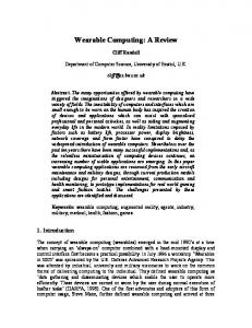
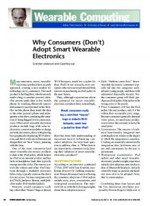
The final version of TEAPC is shown in Figure 4, with its major relevant components listed in Table 1. Figure 5 is a photograph of TEAPC.
A simple on/off switch was added for the disaster tolerance experiment. An external power meter with a serial interface was also added to measure changes in total PC power consumption.
4.1 Final TEAPC System With the external sensors and associated extra control hardware eliminated from the system, the new parts of the TEAPC solution are only software, utilizing hardware information and control paths already existing on the motherboard. Referring to Figure 4, the teapc program reads the CPU’s core temperature, core voltage, and fan speed from the Super I/O chip. The program reads and sets the CPU frequency by accessing the Clock Synthesizer. Likewise, the program reads and sets the CPU core voltage via the Vcore Regulator Controller. The Synthesizer and Regulator are accessed with the twowire SMBUS through the Southbridge. Program access to all of these components, as well as the control registers of the chipset itself, is made via the x86 I/O address space. Readily-available freeware off of the Web is used to directly access the I/O space from within the (Windows) program. Presumably, a commercial version of the software would use safer indirect access within the Windows API (Application Program Interface).
4.2 Software Realization of Modified TEAtime Algorithm. The TEAPC control program was written in C and C++. The program is only 800 Kbytes large, including the feedback control system. teapc uses less than 1% of the CPU’s time; see Section 5.6. The control loop is updated every second. This is straightforward. The non-CPU parts of the control loop are represented in the program by a list of the blocks previously shown. At an update point, the program starts with the input data (the runningaveraged CPU temperature), and re-calculates the control block values around the loop. The new CPU frequency is the main output, with the CPU core voltage sometimes linked to the frequency. For safety, the maximum and minimum possible output frequencies are hard limits; when reached, we say the frequency has “pegged” (as in an old analog meter). In all of the experiments, the rate of change of frequency with respect to time was solely determined by the control system’s dynamics.
5 Experiments The experiments characterized TEAPC’s operation and demonstrated its achievement of the project’s goals. Only the CPU frequency was directly varied by the feedback control system. The Northbridge and memory clock frequencies are a fixed fraction of the CPU frequency, and thus also change. In three cases the CPU core voltage was varied as a function of the CPU clock frequency. All other components in the PC used their standard operating conditions, in particular their normal frequencies and voltages. In general, we see that although there is some oscillation in the dependent variables, it is not great. The CPU temperature may still oscillate, even with a constant CPU frequency; this is mainly due to load changes in the CPU-100%-loading burn-in program (SiSoft’s Sandra). In the experiments, Tset was often set to a point lower than that needed for maximum performance. This was done both to characterize the system and to demonstrate its operational flexibility; see Table 3.
5.1 Step Response to Frequency Change Table 2 shows TEAPC’s CPU temperature’s reaction speed to changes in CPU frequency. Overall, the CPU neither heats up or cools very quickly. The settling time varies substantially with load and direction of frequency change. It is relatively easy to heat up the CPU, but takes considerably longer to cool it, regardless of the CPU’s load. This is intuitive, as it is usually the case in thermodynamics that forced addition or removal of energy to a system will heat up or cool, respectively, faster than with a passive transfer mechanism. In TEAPC’s case the increasing frequency directly increases the CPU’s power consumption and temperature, whereas removal of the resulting heat depends on the thermal resistance and capacitance of the passive cooling system.
page 5 of 12
FSB
CPU Intel P4
Main Memory 1 GB Dual Channel 400 MHz Ultra
Northbridge Intel 875P
VID
(Environment Monitor)
CPU Vcore Regulator Control Vcore
Southbridge I/O Controller Intel ICH5R
VID
CPU Vcore Power Supply
LPC Bus
Super I/O ITE 8712F
CPU Fan Speed
SMBUS - IIC Bus Clock Synthesizer ICS 952635
CPU Clock (FSB - Front Side Bus)
CPU core Temp.
CPU Vcore Volt. Memory Clock
Only directly relevant components (LPC - Low Pin Count) and connections are shown.
Figure 4. Major relevant motherboard structures used in TEAPC.
Table 1. Major TEAPC components and extra experimental equipment. PC Component Motherboard CPU Chipset Clock Synthesizer Super I/O (Environment Monitor) CPU Volt. Regulator Control Main Memory
Manufacturer Gigabyte Intel Intel ICS ITE ITE Ultra
Operating System Disk System – RAID 0+1 Disks Equipment for experiments only Fan Controller & Temp. Monitor Power Meter CPU Fan Controller
Microsoft ITE Maxtor Thermaltake Electronic Educational Devices custom
Part Number/Description GA-8KNXP (Rev. 2); w/DPS regulator P4 3.0 GHz, 800 MHz bus 875P, ICH5R ICS952635 IT8712F V0.6 IT8206R V0.1 U10-5903R; 2 x 512 MB; 400 MHz DDR, Dual Channel (Operated at 320 MHz.) Windows 2000 SP4, HT disabled GigaRAID IT8212F 4 x 6E040L0, 40 GB, 133MHz IDE Hardcano 12; for 4 fans, 4 thermocouples watts up? PRO (Note: this is the unit’s model name.) On/Off, control select: MOBO or Hardcano
Table 2. Step response of CPU temperature to CPU frequency changes, under differing loads. Run ID 91 92 93 94
CPU Utilization 100% 100% ~5% ~5%
Frequency Transition (GHz) 3.5 to 2.5 2.5 to 3.5 3.5 to 2.5 2.5 to 3.5
Start Temp. (deg. C.) 59.3 52.5 53.1 48.0 page 6 of 12
End Temp. (deg. C.) 53.7 58.9 48.0 52.9
Settling Time (2%) (sec.) 90 60 170 130
5.4 Load Adapting; Vcore Linking
Figure 5. TEAPC prototype, with experiment instrumentation shown on the display. (Authoridentifying marks whited-out.)
TEAPC also dynamically and automatically adapts to changes in computation load. In Figure 8 the system is initially stable at the upper peg point of 3.5 GHz, and under no load. At the indicated point, the Sandra CPU-burn program is started, putting the CPU under full load. The control system senses the rapid increase in CPU temperature, and immediately drops the frequency. Within about 50 seconds TEAPC’s frequency has dropped to about 2.65 GHz, on average, while the CPU temperature has stayed relatively constant around the temperature set point. The power consumption stays about the same. In this case, the CPU core voltage was held constant at its high value, 1.5125 V., and was not linked to the frequency.
Interestingly, the response times approximately double from a full load condition to an approximately unloaded condition. This may arise from the internal CPU power control system, which shuts down major sections of the CPU when the sections are not used. Hence, in a lightly loaded system a given increase in frequency increases power consumption less than a fully loaded system; in the latter, the entire chip is affected by the frequency change, decreasing the response time.
We performed the same experiment, this time with the CPU core voltage a function of frequency. The highest frequency corresponds to the highest voltage, and the lowest frequency corresponds to the lowest voltage. The results are shown in Figure 9. The lower voltage and hence reduced requirement for power allow a higher final operating frequency, about 3.0 GHz, with no change in the power consumption. Thus, the voltage-to-frequency linking results in higher performance for the same power consumption.
5.2 Performance Maximization
5.5 Disaster Toleration and LowPower Setting
Figure 6 demonstrates TEAPC’s ability to operate at better-than-worst-case performances via dynamic adaptation of the clock frequency to desired changes in operating temperature. In the figure, TEAPC is under full load and starts executing in an underclocked power-saving mode, then has its Tset raised appropriately. TEAPC rapidly increases its frequency, strictly in response to the control system. It reaches full performance (the hard upper-limit ‘peg’) within about 10 seconds, even though it takes longer for the actual CPU temperature to reach its final value. The CPU core voltage was held constant at its high value, 1.5125 V., and was not linked to the frequency.
5.3 Modest Frequency Changes Figure 7 shows the results of a small step change in frequency, midway between the two peg points. Voltage-to-frequency linking was used. By raising Tset, the frequency was changed from 2.75 GHz to 3.25 GHz, with the final average value reached after about 150 seconds. From the results we see that small frequency changes are also handled by the control algorithm, although pegging may still occur to a limited degree.
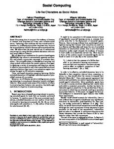
The disaster tolerance experiment consists of turning off the CPU’s cooling fan while the CPU is under full load and at its “maximum” frequency. Moving air from a fan through a passive heatsink greatly lowers the heatsink’s thermal resistance and thus greatly increases the amount of heat a heatsink can dissipate. Hence, stopping the fan is a disastrous condition, and an excellent test of TEAPC’s adaptation abilities. Figure 10 shows TEAPC’s response first to fan ‘off’ and then fan ‘on’ conditions. Initially, the CPU ran at its “maximum” frequency of 3.50 GHz and a corresponding core voltage of 1.5125 V., and while under full load. The CPU’s core voltage was linked to the CPU frequency. As is shown in the figure, shortly after the CPU’s fan was turned off the CPU temperature began to rise, causing the control system to lower the CPU’s frequency (and hence also its core voltage). Since the CPU’s temperature never dropped below the Tset value of 56 degrees C., the control system dropped the CPU’s frequency all the way down to its “minimum” value of 1.1 GHz and the corresponding minimum core voltage of 1.0875 V.
page 7 of 12
1.5
2.5
1.4
2
1.3
1.5
1.2
CPU Freq. (GHz) PC Tot . Pwr. (100's of W.) CPU Voltage (V.)
1.6
3
1.5
2.5
1.4
2
1.3
1.5
1
1.1 0
50
100
150
200
55
54
54 Temperature (deg. C.)
55
53 52 51 50 49 Temp. Set (deg. C.) Temp. CPU Raw (deg. C.)
48
1.2
CPU Freq. (GHz) PC Tot . Pwr. (100's of W.) CPU Voltage (V.)
1
Temperature (deg. C.)
3.5
CPU Core Voltage
3
CPU Freq. & PC Total Power
1.6
CPU Core Voltage
CPU Freq. & PC Total Power
3.5
0
100
200
300
1.1 400
53 52 51 50 49 Temp. CPU Raw (deg. C.) Temp. CPU Averaged (deg. C.)
48
Temp. Set (deg. C.)
Temp. CPU Averaged (deg. C.)
47
47 0
50
100 150 Tim e (seconds)
200
0
100
200 300 Tim e (seconds)
400
Figure 6. "Maximize" performance adaptation. Vcore not linked to CPU frequency.
Figure 7. Small step adaptation, 2.75 GHz (Tset=48 C.) to 3.25 GHz (Tset=52 C.). Vcore is linked to CPU frequency.
At this point we ran other applications to test the capabilities of the CPU at such extreme conditions. At the low frequency, TEAPC was still functional; no OS or other crashes occurred, the burn program still worked, and Web browsing was fully functional and executed simultaneously with the burn and a PowerPoint presentation. Sample web pages included video clips. Therefore, while the system operates at reduced performance, it is still functional at the low frequency and voltage, with the CPU fan stopped; disaster tolerance is achieved. (In a production system more extensive testing would be needed.)
The CPU temperature dropped slightly while the frequency and voltage decreased, then rose slightly to a steady 59 degrees C. (The CPU can operate safely up to 70 degrees C.; this is an Intel specification.)
(Note that while other applications are running in the foreground, teapc is not active due to the nature of its construction as a “console” application in Borland C++ Builder 6, the IDE (Integrated Development Environment) used for teapc. This is why no data points are shown in the vicinity of t = ‘A’ seconds. In a production system this phenomenon would not occur, and teapc would always be active.)
After the fan was turned back on, the control system sensed the drop in the CPU’s temperature and increased the CPU’s frequency. Thus, TEAPC always adapts to the existing conditions, taking advantage of favorable ones as well. Disaster recovery is also achieved. The power savings at the low frequency and voltage settings were substantial. The overall PC power decreased from about 218 W. down to 132 W., under full load, a power savings of about 40%. Underclocking is a useful tool.
page 8 of 12
1.5
2.5
1.4
2
1.3
1.5
1.2
CPU Freq. (GHz) PC Tot. Pwr. (100's of W.)
3.5
1.6
3
1.5
2.5
1.4
2
1.3
1.5
55
0
100
200
300
1.1 400
1 55
Temp. CPU Raw (deg. C.) Temp. CPU Averaged (deg. C.)
54
0
100
Temperature (deg. C.)
Temperature (deg. C.)
Temp. Set (deg. C.)
52 51 50 49 48
200
300
1.1 400
Temp. CPU Raw (deg. C.) Temp. CPU Averaged (deg. C.) Temp. Set (deg. C.)
54
53
1.2
CPU Freq. (GHz) PC Tot . Pwr. (100's of W.) CPU Voltage (V.)
CPU Volt age (V.)
1
CPU Core Voltage
3
CPU Freq. & PC Total Power
1.6
CPU Core Voltage
CPU Freq. & PC Total Power
3.5
53 52 51 50 49 48
47
47 0
100
200 300 No lo ad -to - Full lo ad Tim e (seconds)
400
0
100
No lo ad -to - Full lo ad
200 300 Tim e (seconds)
400
Figure 8. Load adaptation test. Vcore NOT linked to CPU frequency.
Figure 9. Load adaptation test. Vcore IS linked to CPU frequency.
5.6 Overhead
consumption, the performance dynamics are likely to be as complex as the dynamics of the workload itself, if not more complex. However, the net mean performance is not likely to change, and unstable performance dynamics should be avoidable with a well-designed control system.
We measured teapc’s CPU utilization (overhead) during full load operation with the feedback control system engaged, but with the experimentation instrumentation and display system turned off; this would be the normal mode of operation in a production system. teapc ran in the foreground. The measurements were made with a standard ‘performance counter’ built into the Windows API. teapc used less than 1% of the CPU under the above conditions. In fact, teapc’s CPU utilization was less than the minimum increment of the performance counter (about 0.4%); most of the time the indicated utilization was 0%. In other words, teapc adds practically no execution time overhead to the PC’s operation and thus no performance is lost.
5.7 Real Workload Effects If TEAPC is operated in an intermediate mode, between maximum performance and minimum power
For example, first consider Figure 6; the frequency is approximately constant, and the core voltage is constant. However, the Sandra burn-in code appears to have three distinct phases of operation, each one using different parts of the CPU and hence using a different amount of power; notice the step-function shape of the power consumption. This shape repeats with each run of the burn-in code; each run executes for about 30 seconds. Next, consider Figure 7, with TEAPC operating in an intermediate mode, in which the frequency can vary. The power curve is no longer neat, but mirrors the complexity of both the frequency and temperature curves. However, also note that the mean performance is relatively stable.
page 9 of 12
1.6 CPU Freq. (GHz) PC Tot . Pwr. (100's of W.) CPU Volt age (V.)
1.5
2.5
1.4
2
1.3
1.5
1.2
1
1.1 0
Temperature (deg. C.)
CPU Core Voltage
3
50
100
150
200
250
60
4.0
59
3.5
58
3.0
57
2.5
56
2.0 Temp. CPU Raw (deg. C.) Temp. CPU Averaged (deg. C.) Temp. Set (deg. C.) CPU Fan Speed (KRPM )
55 54
1.5 1.0
53
CPU Fan Speed
CPU Freq. & PC Total Power
3.5
0.5
52
0.0 0
50
A
100
150 Time (seconds)
CP U Fan turned OFF
200
250
CP U Fan turned ON
Figure 10. Example of disaster tolerance and recovery: CPU fan turned off then back on; system under full load. TEAPC remains functional at the low frequency and core voltage, even with the fan off. TEAPC continuously adapts to take the best advantage of existing conditions. We observe an interesting phenomenon in Figure 7 and Figure 9, in both of which the core voltage is linked to the frequency: The AC part of the frequency data has the shape of an amplitude-modulated signal, with the ‘carrier’ period being the same as the period of the burn program’s runs (30 seconds). The modulating signal seems to have a period of about 220 and 160 seconds in Figure 7 and Figure 9, respectively. The characterization, investigation and comprehensive explanation of this phenomenon is a subject for future work.
6 TEAPC Operation in Practice TEAPC can be operated in many ways depending on the needs or desires of the user. The user or operating system may change the operating characteristics dynamically to suit current demands. Only Tset need be changed to accommodate different circumstances. For examples, see Table 3.
7 Summary TEAPC demonstrates the numerous and deep possibilities inherent in modern PC’s when advantage is taken of low-level inputs and outputs, and, most especially, when a well-designed feedback-control system is used. Many of the TEAtime attributes have been realized in TEAPC, as well as many more. TEAPC demonstrates: operation at better-than-worstcase performance levels, adaptation to varying environmental and CPU loading conditions, disaster tolerance, and low-power/high reliability operation. We feel TEAPC could open the way for much more versatile and cost-saving PCs, in many cases those that already exist. Underclocking is a great tool to help achieve several of these features.
page 10 of 12
Table 3. Some possible operating scenarios. Goal
Tset Comments
Lowest power, highest Low reliability Frequency and CPU core voltage are minimized, minimizing power consumption and maximizing reliability. Suitable for web browsing (even with broadband access), email and casual use. Could be the normal setting for nighttime operation in an office, to minimize operating costs yet provide the reliability of “always on” operation. Mid-range power, Mid-range reliability Frequency and core voltage change to maintain a constant CPU temperature equal to the Tset value. Power could still be low, with high reliability. More computationally-demanding tasks could be run, with negligible delay, e.g., limited animation, large Excel worksheets, etc. High: frequency is pegged Highest performance at its maximum value In the case of the prototype, this would be a case of limited overclocking. Reliability is minimized and power maximized, but performance is also maximized. Useful for computationaly-intensive tasks, such as FPGA net routing, or game playing. (The maximum frequency could also be set for no overclocking.) Could also be the daytime setting in an office, so as to minimize response time during working hours. Disaster tolerance Any For all practical purposes, TEAPC is always enabled for disaster tolerance. Environment change Any tolerance With high ambient temperatures TEAPC adapts the system so as to keep the CPU temperature within specifications. Performance is limited, but the system still functions. Conversely, with low ambient temperatures the more favorable conditions can give improved performance.
References [1] T. D. Burd, T. A. Pering, A. J. Stratakos, and R. W. Brodersen, "A Dynamic Voltage Scaled Microprocessor System," IEEE Journal of Solid-State Circuits, vol. 35, no. 11, pp. 15711580, November 2000. [2] D. Ernst, N. S. Kim, S. Das, S. Pant, R. Rao, T. Pham, C. Ziesler, D. Blaauw, T. Austin, K. Flautner, and T. Mudge, "Razor: A Low-Power
Pipeline Based on Circuit-Level Timing Speculation," in Proceedings of the 2003 International Symposium on Microarchitecture. San Diego, Calif., USA: IEEE, ACM, December 2003. [3] G. F. Franklin, M. L. Workman, and D. Powell, Digital Control of Dynamic Systems, 3rd ed: Prentice-Hall, 1997. [4] T. Kuroda, K.Suzuki, S. Mita, T. Fujita, F.Yamane, F. Sano, A. Chiba, Y. Watanabe, K. Matsuda, T. Maeda, T. Sakurai, and T. Furuyama, "Variable Supply-Voltage Scheme for Low-Power High-Speed CMOS Digital Design," IEEE Journal of Solid-State Circuits, vol. 33, no. 3, pp. 454-462, March 1998. [5] M. Miyazaki, J. Kao, and A. Chandrakasan, "A 175mV Multiply-Accumulate Unit Using an Adaptive Supply Voltage and Body Bias (ASB) Architecture," in Proceedings of the International Solid-State Circuits Conference (ISSCC). San Francisco, CA, USA: IEEE, February 3-7, 2002. [6] M. Olivieri, A. Trifiletti, and A. De Gloria, "A Low-Power Microcontroller with On-Chip SelfTuning Digital Clock Generator for VariableLoad Applications," in Proceedings of the 1999 International Conference on Computer Design: IEEE, 1999. [7] E. Rohou and M. Smith., "Dynamically Managing Processor Temperature and Power," in Proceedings of the 2nd ACM Workshop on Feedback-Directed Optimization (FDDO-2). Haifa, Israel: ACM, November 1999. [8] A. E. Sjogren and C. J. Myers, "Interfacing Synchronous and Asynchronous Modules Within a High-Speed Pipeline," in Proceedings of the 17th Conference on Advanced Research in VLSI (ARVLSI '97), 1997, pp. 47-61. [9] K. Skadron, T. Abdelzaher, and M. R. Stan, "Control-Theoretic Techniques and ThermalRC Modeling for Accurate and Localized Dynamic Thermal Management," in Proc. of the 2002 International Symposium on HighPerformance Computer Architecture. Cambridge, MA, USA: IEEE, 2002. [10] K. Skadron, M. R. Stan, W. Huang, S. Velusamy, K. Sankaranarayanan, and D. Tarjan, "Temperature-Aware Microarchitecture," in Proceedings of the 30th International Symposium on Computer Architecture. San Diego, CA, USA: IEEE and ACM, June 2003. [11] A. K. Uht, "Achieving Typical Delays in Synchronous Systems via Timing Error Toleration," Department of Electrical and Computer Engineering, University of Rhode Island, Kingston, RI, Technical Report 032000-
page 11 of 12
[12]
[13]
[14]
[15]
0100, March 10, 2000. Available via http://www.ele.uri.edu/~uht. A. K. Uht, "Uniprocessor Performance Enhancement Through Adaptive Clock Frequency Control," in Proceedings of the SSGRR-2003w International Conference on Advances in Infrastructure for e-Business, eEducation, e-Science, e-Medicine, and Mobile Technologies on the Internet. L'Aquila, Italy: Telecom Italia, January 6-12, 2003. A. K. Uht, "Going Beyond Worst-Case Specs with TEAtime," Computer, vol. 37, no. 3, pp. 51-56, March 2004. A. K. Uht, "Uniprocessor Performance Enhancement Through Adaptive Clock Frequency Control," IEEE Transactions on Computers, 2005. In press. R. J. Vaccaro, Digital Control: A State-Space Approach: McGraw-Hill, 1995.
page 12 of 12