Techniques for very low-voltage operation of continuous-time analog CMOS circuits Jaime Ramirez-Angulo1, Ramon Gonzalez-Carvajal2 and Antonio Lopez-Martin3 1 New Mexico State University, 2Escuela Superior de Ingenieros , 3Universidad Publica de Navarra
[email protected] [email protected] [email protected] Abstract In this paper some techniques for continuoustime operation of low-voltage analog CMOS circuits are revisited These are based on the utilization of static, dynamic and switched floating voltage sources, on floating and quasifloating gate transistors and on a versatile cell denoted flipped voltage follower. Circuits based on these techniques operate with a single supply voltage close to a transistor's threshold voltage
quasi-floating gate transistors and c) on a versatile cell denoted flipped voltage follower. These circuits operate in all cases with a single supply voltage close to a transistor's threshold voltage and with large signal swings. We refer to low-voltage circuits as those that operate from a single supply voltage VDD less than the sum of the threshold voltages of a PMOS and an NMOS transistor: VDDVSGp+VDSsat. In order to reduce the supply requirements of the op-amp output stage an “inverted” (or negative) battery can be used [4]. In this case the supply requirements of the
Proceedings of the 17th International Conference on VLSI Design (VLSID’04) 1063-9667/04 $ 20.00 © 2004 IEEE
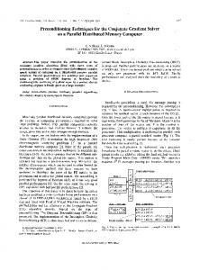
Fig. 4 (a) Class AB op-amp output stage with inverted DC floating source Vb (b) Resistor implementation (c) Dynamic Implementation . IIb. Dynamic floating sources. Fig. 5a shows the scheme of a conventional voltage follower with input supply requirements VDD>VSGp+VDSsat +Vinswing. Fig. 5b shows a transposed version with the positive input terminal connected to a constant voltage and a floating source with value Vs connected between the output and the negative input terminal . This circuit has reduced supply requirements since no input swing is required. Fig. 4c sows the implementation of the floating source Vs using matched current sources (as in Fig. 1c) with value Ib=Vs/R and a resistor R. Fig. 4d shows the use of an auxiliary differential amplifier (denoted DA) to generate currents with value Ib=Vs/R. Fig. 4e shows the implementation of the current sources of 4c. Nonunity gain amplifiers with gain A can be easily implemented by using scaled currents with value AIb (instead of Ib) as shown in Fig. 5e. This results in an output voltage Vout=Avs [7] .
Ib + _ Vs
OA
Vo
OA
Vo
OA
Vo
Vs _+ Ib
(a)
Ib
A
(b)
Vref C
V's
R
Ib
B
+
_OA
A
Ib
Ib=Vs/R
(c) Vref
+ _ DA
R
Utilization of MIFG differential pairs in the input stage of an operational amplifier with negative feedback leads to VFGd = 0. A wide variety of applications can be derived from this expression [9]. As example Fig. 7b shows the scheme of a three input low voltage adder where Vo=a1V1+a2V2+a3V3 with ai=Ci/Ctotal.
Vcn
A Ib
R
1
Vout=AVs
P o ly II
2 A
P o ly I
n
B
A Ib
(d)
D iffu s io n
B
D
S
(e)
G
Fig. 5 (a) Conventional voltage follower (b) Transposed version (c) Implementation with resistor and matched current sources (c) Auxiliary circuit to generate Ib (e) Implementation of non-unity gain amplifier.
( a ) D
D
Cgd C1
Cgb
1
1
C2
2
2
3. Low-voltage circuits based on Multiple input floating-gate transistors
B Cn
n
n
Cgs
IIa. Conventional Floating gate circuits. Another low-voltage scheme is based on utilization of multiple input floating gate transistors (MIFGs see Fig. 6). In these transistors the gate is left floating. They have “n” control inputs capacitively coupled to the floating gate through (poly I-poly II) capacitors C1,C2,..Cn. Based on charge conservation it can be shown that the voltage at the floating gate VFG is given by the weighted voltage addition of the control voltages according to VFG= (V1C1+V2C2+..+VnCn)/Ctotal
S
S
( c )
( b )
Fig. 6 Multiple Input Floating Gate Transistor: (a) Layout (b) symbol (c) Equivalent circuit model.
Vn+
Ib
Cn
C1 Vn-
V1+ C1
C1
V1
C1
V2 V3
C2 C3
Clarge
V1-
Clarge
Vout
+ _ C2
_ _
C1
_
C3 Clarge
+ + +
Vbias
The basic principle for low-voltage operation with MIFGs consists of using one terminal for biasing purposes and the remaining terminals for signal injection as shown in Fig. 7 for a differential pair with three input floating gate transistors [8]. In this case one control terminal of each MIFG transistor is connected to a value Vbias (In Fig. 7 Vbias=VSS). If the capacitors associated to the basing inputs have values Clarge much greater than the remaining capacitors (Clarge>>C1,C2,..,Cn) then the quiescent point of the floating gates VFGQ of M1 and M2 is set approximately to the rail value: VFGQ=VSS. This minimizes the supply requirements of the differential pair. The differential floating-gate voltage depends only on the input differential voltages Vd1, Vd2, ..,Vdn according to VFGd = VFG1-VFG2 = Vd1(a1)+Vd2(a2)+..+Vdn(an) e.g. Vd1=V1+ V1- and ai=Ci/Ctotal are the relative weights.
Proceedings of the 17th International Conference on VLSI Design (VLSID’04) 1063-9667/04 $ 20.00 © 2004 IEEE
(a)
(b)
+ _
CF=Ctotal-Clarge Clarge
(c)
Fig. 7: (a) MIFG low-voltage differential pair (b) MIFG low-voltage summing amplifier (c) Setup for analysis of gain-bandwidth product. The MIFG approach for low-voltage operation has following drawbacks: a) The charge trapped in the floating gate can lead to
large (temperature dependent) DC offsets, b) The biasing capacitance Clarge forms voltage divider with the remaining capacitances which appear as feedback elements with value CF=Ctotal-Clarge (see Fig. 7c). This reduces the effective gain-bandwidth by a relatively large factor K=1+ Clarge/(Ctotal-Clarge) IIIb. Quasi-Floating gate transistors. Some of the disadvantages of floating gate transistors can be overcome by utilization of quasi-floating gate (QFG) transistors [10]. In these circuits the gate is also capacitively coupled to input signals V1,V2,..Vn. The difference with respect to conventional MIFG transistors is that the gate is not left floating but it is weakly connected to a supply rail using a very large valued resistor Rlarge (see Fig. 8). This sets the quiescent gate voltage to the supply rail voltage and thus minimizes supply requirements. Rlarge is implemented in practice using a reverse biased PN junction (Fig. 8). Rlarge in conjunction with the coupling capacitors forms a high pass circuit with very low cutoff frequency (fractions of a Hz). The QFG technique has following advantages over true floating gate circuits: a) No charge can be trapped in the gate, b) The gates have well defined quiescent voltages that minimize circuit’s supply requirements, c) Input signals can have arbitrary DC components, d) No gain-bandwidth degradation takes place
Limitations of the QFG technique. In feedforward applications (like the mixer of Fig. 9a) the swing at the junction implementing Rlarge must be limited to a0.4V in order to avoid forward biasing the PN junction. Closed loop applications (like the amplifier of Fig. 10a) are not subject to this limitation but they require an auto-zeroing circuit to avoid op-amp saturation by the DC offset which is subject to the open loop gain. RL
RL
Vout
Vout 2
1
Rlarge
Rlarge Vin1a
_
Vout
+
C
Vin2a
M1
Rlarge
Vin1b
Vin1b
Vin2a
Vin2b
C
M2
C
Rlarge Vin1a C
M3
M4
Vin2b C
C
C C
S
M5 4Ib
Vbias
(a) Vdd Vclk
MRlargeP
Vclksh
Vdd Vdd C MpassN Vclknsh
Vclkn MpassP Vin
+ –
Vdd
Vout
C
Chold -Vdd MRlargeN
(b)
Fig. 9 a) QFG mixer (b) Low voltage rail to rail sample and hold based on QFG switch
Fig. 8Layout of Quasi-floating gate transistor and equivalent circuit QFG Applications. Fig. 10. shows a programmable gain amplifier based on the QFG technique [11]. Fig. 9a shows a low-voltage mixer [10] and Fig. 9b a low voltage sample railto-rail switch [12]
Proceedings of the 17th International Conference on VLSI Design (VLSID’04) 1063-9667/04 $ 20.00 © 2004 IEEE
Fig. 10 Programmable gain QFG amplifier
4. Circuits based on flipped voltage followers Low-voltage circuits based on a cell denoted “Flipped Voltage Follower” (FVF) [13] are discussed next. The FVF is a cascode amplifier with feedback. It operates as an improved voltage follower biased on the drain (rather than on source side). It has a node with very low impedance Rx=(1/gm)(1/gmro) the other two nodes (“y” and “z” are high impedance nodes. The impedance at node “z” is high and given by Rz=ro(gmro). The FVF has very low voltage requirements at node “x”: (on the order of VDSsat.) This together with the very low impedance at node “x” and its large current sinking capability is used with advantage for the implementation of many low-voltage (mostly class AB) circuits [13]-[15]
high frequency pole that reduces the bandwidth of circuits based on the FVF. Fig. 11b shows a “folded” version of the FVF. (The flipped folded voltage follower FFVF). In this circuit the swing at “y” is not limited by the transistor threshold voltages. Ib Ib B Vicm+Vi
B Vicm+Vi
M1
M1
iA MLS
IA
C
A
M2
A I1
2Ib
M2 ILS
(a)
( b)
Fig. 11 FVF with improved Input swing: (a) FFV with level shifter MLS (b) Folded version of flipped voltage follower for high bandwidth and wide signal swing.
Rz HIGH! Ibias Vz Ry VERY HIGH!
M4
M4P
Va'
Vb'
Iin
M1 Vy
V1
M1
M3
Va
M1P
M2
I out1
M2
LOW!
Vb
M3P
M2P
V1
V2
Ib I1
Ib
I1P
I 2P
Ib
I2
Ib
Vbias
Vbias
M7
M5 II
Rx M8
I out2
M5P
M7P
M6P
M8P
I II
M6
Fig. 10 Flipped voltage follower. The voltage at “x” follows a signal at node “y” with a DC level shift VGSQ1. Due to its low impedance node “x” can sink large currents without changing essentially its voltage. Current variations at “x” are absorbed by M2 and produce voltage variations at node Vz (usually not in the signal path) which can be used (if required) to replicate the current in M2. A serious limitation of the FVF is that given that its input signal swing is limited (“strangled”) by the gate-source drop of M2 the maximum input peak-to-peak signal swing at “y’ is relatively small and technology dependent. It is given by VinpswP-P=VGS2-VDSsat1-VDSsat2=VTVDSsat2. This value can be as low as a few hundred mV in a modern sub-micrometer CMOS technology with VTa350mV Fig. 11 shows two modified versions of the FVF with increased voltage swing. In Fig. 11a a level shifter MLS has been added to increase the input swing by the drop VGSQ of MLS. This level shifter has been used by several authors. It has two drawbacks: a) it increases the circuit’s supply requirements and b) it introduces an additional
Proceedings of the 17th International Conference on VLSI Design (VLSID’04) 1063-9667/04 $ 20.00 © 2004 IEEE
(a) Ib
Ib
+
-
M1
Vi+ I1
M2
Vi-
I1
2Ib Vc
I2 A
M5 M3
R
iR
in
B
I2 M4 M6
2Ib
2iR
Vc
out
Current mirror
(b)
Fig. 12 Applications of flipped voltage follower (a) Four quadrant analog multiplier (b) Highly linear V-I converter. Applications of FVFs: Fig. 12(a ) shows a four quadrant analog multiplier that uses FVFs (M3,M4 and M3P,M4P) to implement very low impedance sources at the source terminals of a conventional four transistor multiplier cell formed by M1,M2,M1P,M2P [16]. Fig. 12(b) Shows a highly linear (