enabling robust operation of an agile manufacturing. workcell. In particular ... medium-sized and rolling parts; and agile gripper design. methods ..... For any bi-.
TECHNOLOGIES FOR ROBUST AGILE MANUFACTURING Wyatt S. Newman,* Frank L. Merat,* Michael S. Branicky* Virgilio B. Velasco, Jr.,* Nicholas A. Barendt* Andy Podgurski,† Yoohwan Kim,† Ju-Yeon Jo† Roger D. Quinn,‡ Greg C. Causey‡ Case Western Reserve University (CWRU), Cleveland, OH 44106 USA
ABSTRACT This paper describes advances in developing key software, sensing/control, and parts-handling technologies enabling robust operation of an agile manufacturing workcell. In particular, we discuss: a modular software architecture that supports real-time feedback, process scheduling, and workcell extensions; simulation for error detection, visualization, and diagnosis; flexible sensors allowing multiple, programmable quality checks; a generic robot API permitting plug-and-play of heterogeneous robot controllers/networks; flexible feeders accommodating a large variety of parts, including medium-sized and rolling parts; and agile gripper design methods enhancing speed and reliability of parts handling.
software architecture, simulation, and machine vision system together now incorporate technologies allowing automatic error detection with automatic or guided recovery. Also, the workcell was augmented with a new workstation and new robots/controllers with ease. Finally, parts handling for totally new assemblies has been accomplished for a wide variety of parts with our flexible feeders and new, agile gripper design methods and technologies. The result: our workcell hardware and software is now robust with respect to errors, changeovers, augmentations, and introducing new parts.
Keywords: Agile manufacturing, flexible manufacturing, generic robot API, flexible feeders
1
INTRODUCTION
We have developed software, sensing/control, and partshandling technologies that allow unattended operation of an agile manufacturing workcell. Our experimental testbed is the CWRU agile workcell, which has been developed for light mechanical assembly in collaboration with industrial sponsors [1-5]. See Fig. 1. The workcell includes four Adept robots, a Bosch conveyor system, multiple flexible parts feeders at each robot’s workstation, CCD cameras for parts feeding and hardware registration, and various control systems (including Adept MC, Cimetrix, and an in-house dual VMEbus design [1]). The flexible parts feeder was also developed at CWRU [1, 6]; it uses multiple conveyors to singulate parts and machine vision to locate them. Specialized hardware is encapsulated on modular grippers and worktables that can be quickly interchanged for assembly of different products. Object-oriented software (C++) running under VxWorks, a real-time operating system, is used for workcell control. The software architecture for this control code was developed for rapid introduction of new assemblies through code re-use. A simulation of the workcell was also developed, so that controller software could be written and tested off-line, enabling the rapid introduction of new products. Over the past year, a major thrust has been to develop technologies that enable the above workcell to be robust with respect to errors and changes. For example, our *
Department of Electrical Engineering and Applied Physics Department of Computer Engineering and Science ‡ Department of Mechanical and Aerospace Engineering †
FIG. 1: CWRU AGILE MANUFACTURING CELL The paper is organized as follows. In the next three sections, we discuss key software, sensing/control, and parts-handling technologies enabling robust operation, respectively. Section 2 discusses our modular software architecture, which supports easy workcell extensions. We also explain our simulation software for error detection, visualization, and diagnosis. Section 3 discusses our machine vision system, including flexible sensors allowing programmable quality checks. We also introduce a generic robot API that permits plug-and-play of robots/controllers. Section 4 focuses on Flexible Parts Handling. We summarize our flexible feeder design and its ability to accommodate a large variety of parts, including medium-sized and rolling parts. We also propose “agile gripper” design rules that enhance speed and reliability of parts handling, and describe computeraided design tools and rapid-prototyping of such grippers.
2
SOFTWARE
2.1
SOFTWARE ARCHITECTURE
Our object-oriented software architecture for agile manufacturing [7] has three principle agent classes: Assembler, Supplier, and Transporter. These agents and their rules of interaction constitute a reusable “design pattern” [8] for control of an agile manufacturing workcell. An Assembler carries out a particular assembly sequence with the aid of other agents. A Supplier provides parts or subassemblies to one or more assemblers. A Transporter provides services for moving pallets between workstations. These three agents work concurrently and employ the service of a number of auxiliary objects that encapsulate devices and subsystems such as robots, feeders, and the vision system. This architecture successfully captures basic functionality required for agile manufacturing. Despite many changes in the workcell structure and assembly tasks, this architecture has proven to be stable. Important changes are described in the following sections.
2.1.1
PERFORMANCE ENHANCEMENTS
Assembly cycle times have been reduced significantly by incorporating a number of sensors. Previously, some operations were controlled using fixed delays, which caused unnecessary waiting. For example, after initiating a grasp operation, the robot arm was not moved for a fixed period that was long enough to ensure that the robot gripper was fully closed. However, the time actually required varies. With the addition of inductive proximity sensors, we can determine gripper closure immediately. Cycle time was further reduced by improving coordination between robots and the vision system. Before taking a picture, a Part Locator agent must ensure that its vision window is not obscured by a robot's arm. Previously, picture taking was delayed for the full duration of a robot motion. To reduce the delay, robot motion is now monitored dynamically, so that a picture can be taken as soon as the arm moves outside of the vision window. The final performance enhancement involves the scheduling of vision tasks, which share the same image processor. Previously, fixed scheduling priorities were assigned to vision tasks. However, the actual urgency of a particular vision task depends on the status of the assembly task requiring it. For example, it is more important to take a picture of a part for which an Assembler is waiting than to take one of a part not needed immediately. Hence, we now alter the priorities of vision tasks dynamically to reflect the status of its underlying assembly task. On an actual assembly example, altogether the aforementioned enhancements helped to reduce the cycle time by 5 to 10%.
2.1.2
ADDITION OF A NEW ROBOT
A new robot, with a new type of controller, was added to the workcell without change to the software design. Two new classes with a total of 510 lines were added and four classes were updated to use the new classes, affecting only a dozen lines out of about 10,000 lines of C++ code.
The new robot, an AdeptOne, is controlled by Cimetrix controller. A Cimetrix motion command server, running under the LynxOS operating system, waits for commands from a remote Assembler agent. To control the new robot, we implemented several generic robot commands using the Cimetrix API, including MOVE and REQUESTPOSITION. Communication between an Assembler agent and the Cimetrix motion server is performed using TCP sockets. Assembler agents are unaffected by changes in the robots. We have begun to extend this generic API to control a variety of robots for an array of operations. See Section 3.2 for details. A new workstation was also created using the new robot and new transfer stations and sensors. This did not require any changes to the software architecture. New workcell components were accommodated by using existing object classes or refinements (subclasses) of them.
2.2
SIMULATION SOFTWARE
We have been using three-dimensional graphical simulation software for the testing and development of control software for manufacturing workcells [9]. See Fig. 2. In the past year, we have expanded the role of such simulation to include testing/development of automatic error recovery routines and visual assistance for human operators when manual error recovery is necessary.
FIG. 2: SIMULATION OF AGILE WORKCELL The simulation software was designed to echo the extensibility and modularity of the agile workcell in order to accurately and promptly reflect any equipment changes that are made. After successfully modeling repeated modifications to the workcell, our simulation software has shown that it achieves this design goal. The use of this computer simulation has proved to be both effective and efficient in the identification of control software logic errors [9]. The workcell control software is directly tested in the simulator without having to undergo any preparatory modification or conversion, ensuring a direct correlation between the behavior observed in the simulator and that occurring in the workcell. This correlation allows for the immediate isolation and correction of errors affecting the performance of tasks while ensuring that the integrity of the workcell is maintained.
2.2.1
ERROR DETECTION &RECOVERY
Automatic error recovery is an essential element in control software for manufacturing processes involving extended unmanned operation. Testing such routines in the real workcell, however, can be either expensive or impossible. When first developed, the simulator was limited to testing normal control flow conditions, but in the past year, the simulator was augmented with the ability to generate emulated hardware malfunctions that are difficult or impossible to bring about in the real workcell. This enhanced capability allowed exhaustive testing of error recovery routines. The use of simulation has proven to be especially helpful in testing error-prone routines, reducing the cost and time involved from development to implementation. For those instances when automatic error recovery isn’t feasible, we have developed a visual assistance interface for manual error recovery using graphical simulation. The interface shows the human operator an animated replay of workcell malfunctions and recovery procedures. The simulator identifies error situations via on-line communication with the workcell control software and relays the information to the operator by zooming in on the offending area, causing the region of the malfunction to blink or change colors, and/or emitting a sound alert. This graphical guidance enables new operators to become familiar with system malfunctions in an intuitive manner, facilitating the learning process and the correction of workcell error.
3 3.1
FLEXIBLE SENSING AND CONTROL AGILE MACHINE VISION
The Agile Manufacturing Workcell uses machine vision in several different capacities: flexible parts feeding, hardware registration, and “flexible” sensoring for automation. The flexible parts feeder uses machine vision to localize a part on an underlit vision window [6]. Compared to alternatives like vibratory bowl feeders, machine vision can accommodate a wide variety of parts with minimal hardware changes by replacing mechanical fixtures with vision software. In order to decrease changeover time between different products, no precision mechanical alignment techniques are used (e.g., locator pins). Instead, a camera mounted on the robot is used to register hardware in the robot's coordinate system [1, 5]. Similarly, pallets are machined with three fiducial points and are registered every time a pallet enters the robot's workspace on a spur. “Flexible” sensoring refers to the use of a vision sensor and software for sensing applications which typically would use a dedicated sensor (such as an optical throughbeam sensor) for each hardware assembly. The decreasing costs and increasing computational power of machine vision systems make it economical to replace several such dedicated sensors with a single camera, which can be re-programmed for each assembly’s sensor requirements. This is especially attractive in agile manufacturing systems which already require the use of machine vision. This is the case with our workcell, where a vision system is necessary for flexible feeding. Taking advantage of this in-place resource, we have introduced inspection procedures where a single camera performs
four different assembly checks (see Section 3.1.3 for more details).
3.1.1
CURRENT SYSTEM LIMITATIONS
Up to the present, the machine vision requirements of the workcell have been met by an AdeptVision system. This system provides many of the tools necessary, including image acquisition, connected-component labeling, feature extraction, inspection primitives, and camera-to-robot calibration. However, the AdeptVision system has some limitations for agile manufacturing. Specifically, the lack of extensibility is a major problem. If a particular machine vision operation is not provided by the AdeptVision software, there is no way for a developer to add it to the system. In addition, some operations are not necessarily implemented in a manner a developer would prefer (e.g. the frame subtraction operator does not allow the absolute difference of two images to be calculated). The inherent limits of the V+ language and operating system [1, 5] also limit development using AdeptVision. The proprietary nature of both the AdeptVision hardware and software limits its portability. Unfortunately, there are few platform-independent machine vision solutions available (e.g., VisionBlox). Finally, in a complex workcell, the machine vision system must be shared among many tasks. The primitive multi-tasking provided by Adept’s V+ operating system makes this difficult, if not impossible. (This also affects cycle times, as discussed in Section 2.1.1). With these points in mind, the development of a non-AdeptVision, platform independent machine vision solution began.
3.1.2
NEW SYSTEM ARCHITECTURE
In designing the new machine vision system, we had several goals, including: reproducing the useful features of the AdeptVision system, making efficient use of limited and expensive hardware resources, producing a hardware-independent API portable to a wide variety of systems, and producing a maintainable, extensible design. A client/server model was chosen in order to guard access to vision hardware as well as provide for remote vision applications. The server design addresses both hardware and software concerns. In order to maximize concurrency, the server is multi-threaded. Specialized machine vision hardware often allows a number of operations to occur simultaneously (e.g., image acquisition, an ALU operation, and host access to frame memory), while resource allocation can take place on the host processor at the same time. Such operations can be carried out by multiple, independent “threads” of control. Obviously, only server threads are allowed to touch the vision hardware, and only then through a narrow interface provided by a C++ class. This class is a subclass of an abstract base class which provides vision primitives supported by a wide range of systems. Encapsulating hardware details in this way allows our architecture to support a variety of manufacturing systems. Systems which have limited machine vision hardware, (e.g., only a frame grabber) require that more of this functionality be emulated by the host processor. Systems which have accelerated machine vision hardware (e.g., look-up-tables or neighborhood processors) can efficiently use this hardware, lessening the load on the host processor. Clients communicate with the server using a simple,
remote method invocation implemented using TCP/IP sockets. The server interprets these requests from the clients, performs the requested action, and sends a reply back. Proxy classes [8] are used by the client, hiding this communication mechanism and simplifying the API for the application developer.
3.1.3
RESULTS AND FUTURE WORK
At the time of this writing, the foundations of this client/server architecture have been implemented (i.e. server classes, hardware classes, distributed object calls, and client proxies), with support for low-level machine vision functionality: image acquisition, image subtraction, binary thresholding, and Area-of-Interest (AOI) processing. In order to perform useful work in a robotics environment, a number of machine vision tools are still needed, such as connected-component labeling, feature extraction, primitive inspection tools, and camera-to-robot calibration. With this foundation in place, work in these areas can proceed, as can porting the system to a new hardware environment to test the platform-independence of the architecture. Currently, a CCD camera coupled to our machine vision system replaces dedicated hardware like through-beam or proximity sensors. This single, flexible sensor is used to monitor four assembly operations: successful insertion of a part into a fixture, attachment of another part, success of the assembly operation, and removal of the completed assembly from the fixture We are currently improving on this solution. Our goal is to produce a standalone flexible sensor, consisting of a low-cost CMOS camera directly with a DSP, connected to a network such as DeviceNet, for interfacing to the workcell controller.
3.2
HETEROGENEOUS CONTROLLERS
Our approach to accommodating heterogeneous systems is to use a common robot command set (as described in Section 2.1.2) and encapsulate interfacing details within our generic motion functions. For each different robot controller and corresponding robot control language, we write a single control loop that waits for specific commands and executes them sequentially, as received. In this manner, the individual robot controllers require no knowledge of the logic for any application. Instead, the overall workcell controller is responsible for all program flow control and coordination among events. The simple listen-and-execute loops running on the individual robots can be written once and subsequently never edited. Although we can freeze the specific program for each distinct robot controller without losing generality, it is necessary for the system controller to be multi-lingual. It may seem that this requirement merely shifts our complexity upstream. This complication is addressed by encapsulating vendor-specific and communicationsspecific details within generic C++ motion command functions. In this manner, we can introduce new controllers with new robot languages into our system by merely extending our existing commands with function overloading. Extending our commands for a new robot language only requires writing the translation for a small number of primitive move options. (Since all program logic is contained within the system controller, it is not necessary to translate such flow-control commands for each robot language). Similarly, communications interfaces can be made generic as well. For any bidirectional communications medium of sufficient bandwidth, we can construct a corresponding communications protocol that conforms to our generic interface. The specific communications interface can be selected by the programmer within a generic communications function, and details of use are included by the compiler.
Our workcell software is designed to provide a flexible interface to robot controllers while shielding the application programmer from communications and vendor-specific details. At present, our system incorporates three communications means and two controller vendors. Two Adept 550 robots are controlled by an Adept MV controller with a reflective-memory interface [5] and an AdeptOne robot is controlled by an Adept MC controller with a serial interface. Our fourth robot is an AdeptOne robot which we have retrofit with a Cimetrix open-architecture controller [10]. Communications with the Cimetrix controller is via Ethernet and TCP/IP.
Using our generic robot motion command and communication functions, the application programmer need not be a polyglot; our existing motion command functions can continue to be used, and through the use of function overloading, the appropriate translation for each robot type and communication medium will be invoked automatically at compilation time. Thus, heterogeneous robots, controllers and communications media can be accommodated using a homogeneous command set, shielding the programmer from overwhelming detail and enabling ease of maintainability, extensibility and reprogrammability.
Our heterogeneous system thus includes three communications means and two different robot language interfaces. In a conventional approach, one would program specific applications on each of the robot’s controllers using the native robot programming language, then coordinate the robots with simple event I/O communications. Such an approach, however, requires the programmer to be proficient in multiple vendorspecific languages and operating systems. Further, commercial robot programming languages do not support object-oriented programming, which inhibits reuse of code. In addition, having the system control distributed and weakly coupled among multiple platforms makes the system difficult to maintain and modify.
4 4.1
FLEXIBLE PARTS HANDLING FLEXIBLE FEEDERS
While flexibility encompasses every part of the workcell design, including hardware and control software, the ability to feed parts with a wide variety of sizes and shapes is crucial. Conventional feeding methods, such as vibratory bowl feeders, are not practical for flexible workcells because of their specialized nature. When a new or different assembly is produced, the parts relating to the new assembly need to be fed without downtime for designing, tuning, and installing a new feeding system. Several flexible parts feeders are currently being marketed. A major drawback to the current designs has
been their limited capacity, both in terms of part size and hopper volume. In contrast, our design allows the use of larger parts (roughly softball-sized) and larger hoppers. Some parts are difficult to feed because they have no stable orientation, e.g., cylindrical parts. This greatly reduces the cycle time because the vision system must take images and compare them until no change is registered (which signifies that the parts have stopped rolling). We have demonstrated that this time can be reduced by modifying the belt surface. A soft, rough, transparent substrate (e.g., bubble wrap) attached to the belt was found to solve the problem of rolling parts. We have found that cylindrical parts (fluid connectors) quickly reach a stable pose on the horizontal feeder belt when it is covered with bubble wrap. Furthermore, the vision system was not adversely affected by this substrate.
4.2
AGILE GRIPPERS
The design of end-of-arm tooling for use in a flexible assembly cell is critical to its successful operation because this is the part of the workcell that is going to physically interact with the assembly being produced. Well designed grippers can increase throughput, improve system reliability, compensate for robot inaccuracy, and perform value added functions to the assembly. On the other hand, poorly designed grippers can drop or damage parts, hold parts inconsistently, and decrease system and feeder throughput. In the light of the importance of grippers to overall workcell success and robustnessand the fact that offthe-shelf solutions rarely produce satisfactory resultswe have developed both gripper design guidelines as well as a CAD-based technology for gripper design and fabrication. We discuss them in turn below.
4.2.1
GRIPPER DESIGN GUIDELINES
Our guidelines are divided into two sections. The first covers guidelines to improve system throughput and the second covers guidelines to increase system reliability. As can be expected, some guidelines appear in both sections. The first guideline to achieving higher system throughput is to minimize gripper footprint. This is especially important in a vision based flexible feeding application since parts are presented to the system in random orientations and often situated in close proximity to one another. A related rule is to chamfer external gripper edges, which effectively reduces the gripper’s footprint by allowing the grippers to push neighboring parts out of the way as the current part is being approached. Another guideline is to minimize gripper weight. This allows the robot to move with increased speed thereby reducing cycle times. Designing grippers to maintain secure grasp of the part is another way to increase throughput. A more secure grasp of the part allows for higher robot accelerations and decelerations which reduces cycle time. We also have used the following design rules to reduce cycle times by avoiding tool changes. Grippers which grasp multiple parts are one way to avoid such changes. For example, if parts are similarly shaped, it is often the case that a single gripper can handle many different parts by simple designing different features into the jaws. Another method of avoiding tool changes is to use multiple grippers on a rotary wrist mechanism. This
allows several different grippers to be ready for use by the robot without changing tools. This also has the added benefit of allowing multiple parts to be picked up at once. The final system throughput guideline to design functionality into grippers. For example, an extra linear degree of freedom could be designed into a set of gripper fingers to allow them to press a part into the bottom of a cylinder rather than using a dedicated mechanism to perform the task. System Reliability is generally enhanced by designing grippers to work in the presence of errors arising from vision calibration, robot repeatability and accuracy limits, taught location and tool offset inaccuracies, wear, part variations, etc. Here our first is to design grippers to securely grasp the part, which ensures the parts doesn’t shift (or drop) during robot motions minimizing the possibility of a correctly grasped part not being placed into a fixture or pallet correctly. Designing gripper jaws to encompass the part increases grasp sureness (and can be used when excessive force would deform or damage a part). Another design rule is to provide adequate clearance for the gripper to approach parts. Chamfering gripper edges can also help reliability by helping the grippers to compensate for positioning errors: bottomedge chamfers help align parts as they are approached, while chamfers on the parting line help align parts as they are being grasped. Designing gripper fingers whose shape matches the shape of the part being grasped can also increase system reliability by creating a more accurate and secure grasp. Fully encompassing the mounting points of the actuator helps align the jaws and allows the gripper fingers to be taken on and off the actuator without reteaching the tool offset. If a gripper is used for actual assembly (in contrast to a simple pick and place action), then incorporating features into the gripper which align parts before assembly can be helpful. Generous chamfers on the leading edges of the gripper are usually used to accomplish this. Finally, designing functionality into the gripper fingers themselves can increase reliability by minimizing the number of times the part must be handled, hence minimizing error build-up.
4.2.2
CAD DESIGN AND FABRICATION
To extend flexibility to grippers and fixtures, we have developed a CAD-based gripper design and fabrication method [11-13]. In the inevitable tension between the reusability of generic components and the effectiveness and simplicity of custom-designed components, custom grippers and fixtures tend to dominate. At one extreme, robot grippers can include many degrees of freedom, imitating a human hand. However, such complex and expensive devices are not competitive relative to lowcost, pneumatic parallel-jaw grippers. In the past, we have utilized custom finger shapes mounted to pneumatic grippers. These custom finger shapes have required special-purpose design, fabrication and debugging iterations. Further, each such design handles only one specific part shape. Since our assembly operations typically require a robot to handle several distinct parts, we have needed multiple grippers and modular, interchangeable wrists. In recent progress, we have proposed and evaluated a new method for computer-assisted gripper design and fabrication. In our approach, gripper surfaces are
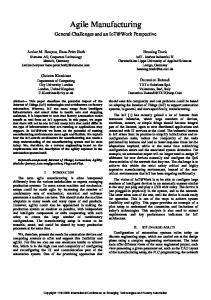
computed by subtracting the extrusion of a part’s CAD model from finger “blanks,” as illustrated in Fig. 3. (The extrusion operation is performed in the gripper-closure direction).
quality checks; a generic robot API permitting plug-andplay of robots/controllers; flexible feeders accommodating a large variety of parts, including medium-sized and rolling parts; and agile gripper design methods enhancing speed and reliability of parts handling.
6
ACKNOWLEDGMENTS
This work has been supported by the Cleveland Advanced Manufacturing Program (CAMP) through the Center for Automation and Intelligent Systems Research (CAISR) and the Case School of Engineering. FIG. 3: COMPUTING GRIPPER FROM A PART.
7
We can repeat the extrusion/subtraction operation for multiple parts, resulting in gripper fingers designed to achieve form closure (or at least frictional form closure [14]) for the entire family of parts using a single gripper design. Resulting computed shapes are evaluated in terms of necessary squeeze force for opposing candidate disturbance forces, per the technique introduced by Brown and Brost [15].
1.
Quinn, R.D., et al. Design of an Agile Manufacturing Workcell for Light Mechanical Applications. In IEEE International Conference on Robotics and Automation. 1996. Minneapolis, MN: IEEE. p. 858-863.
2.
Quinn, R.D., et al., Design of an Agile Manufacturing Workcell for Light Mechanical Applications, 1996, Video Proceedings of the IEEE International Conference on Robotics and Automation: Minneapolis, MN.
3.
Quinn, R.D., et al., An Agile Manufacturing Workcell Design. IIE Transactions, 1997. 29: p. 901-909.
4.
Quinn, R.D., et al., Advances in Agile Manufacturing, 1997, Video Proceedings of the IEEE International Conference on Robotics and Automation: Albuquerque, NM.
5.
Merat, F.L., et al. Advances in Agile Manufacturing. In IEEE International Conference on Robotics and Automation. 1997. Albuquerque, NM: IEEE. p. 1216-1222.
6.
Causey, G.C., et al. Design of a Flexible Parts Feeding System. In IEEE International Conference on Robotics and Automation. 1997. Albuquerque, NM: IEEE. p. 1235-1240.
7.
Kim, Y., et al. A Flexible Software Architecture for Agile Manufacturing. In IEEE International Conference on Robotics and Automation. 1997. Albuquerque, NM: IEEE. p. 3043-3047.
8.
Gamma, E., et al., Design Patterns: Elements of Reusable ObjectOriented Software. 1994, Reading, Massachusetts: AddisonWesley.
9.
Jo, J.-Y., et al. Virtual Testing of Agile Manufacturing Software Using 3D Graphical Simulation. In IEEE International Conference on Robotics and Automation. 1997. Albuquerque, NM: IEEE. p. 1223-1228.
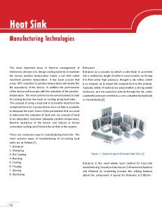
Our resulting finger design models are computationally sliced into planar layers. Each such layer is fabricated by laser cutting sheet material, and the shaped layers are secured together (e.g., clamped within a mounting block) to complete construction of the custom gripper design. Thick layers are used, for convenience of fabrication, but the finite layer thickness is taken into account in computing precise, successful contact points. By this process, one can go from part designs to multi-functional gripper design and fabrication in a time ranging from hours to minutes. Fig. 4 shows the result of a computed thick-layered gripper design for handling three parts—5/16” hex nuts, 3/8” hex nuts, and roughly cylindrical plastic sockets. This design was fabricated and tested. All three part shapes were acquired with high reliability, and the grasp precision was shown to be superior to conventional, planar finger surfaces. Our experience with this experimental example demonstrated the desired properties of: rapid gripper design and fabrication, high reliability of handling a variety or parts, and improved grasp precision.
REFERENCES
10. Anderson, R.L., Open Architecture Controller Solution for Custom Machine Systems. Proceedings of SPIE, 1996: p. 113-127. 11. Virgilio B. Velasco, J., A Methodology for Computer-Assisted Gripper Customization Using Rapid Prototyping Technology, in Department of Electrical Engineering and Applied Physics1997, Case Western Reserve University: Cleveland, Ohio. 12. Virgilio B. Velasco, J. and e. al. Computer-Assisted Gripper and Fixture Customization via Rapid Prototyping. In IASTED International Conference on Robotics and Manufacturing. 1997: IASTED. p. 115-120.
FIG. 4: COMPUTED MULTIPURPOSE FINGERS.
5
CONCLUSIONS
This paper described advances in developing technologies enabling unattended operation of an agile manufacturing workcell. We discussed key software, sensing/control, and parts-handling technologies that enable such unattended operation: a modular software architecture that supports real-time feedback, scheduling, and workcell extensions; simulation for error detection, visualization, and diagnosis; flexible sensors allowing programmable
13. Virigilio B. Velasco, J. and W.S. Newman, Computer-Assisted Gripper and Fixture Customization using Rapid-Prototyping Technology, 1997, Case Western Reserve University: Cleveland, OH. 14. Trinkle, J.C. A Quantitative Test for Form Closure Grasps. In IEEE International Conference on Intelligent Robots and Systems. 1992: IEEE. p. 1245-1251. 15. Brown, R.G. and R.C. Brost. A 3-D Modular Gripper Design Tool. In IEEE International Conference on Robotics and Automation. 1997. Albuquerque, NM: IEEE. p. 2332-2339.