J OURNAL OF P ROPULSION AND P OWER Vol. 14, No. 5, September – October 1998
Technology and Application Aspects of Applied Field Magnetoplasmadynamic Propulsion Gerd Kru¨ lle* DLR, German Aerospace Center, D-74239 Lampoldshausen, Germany Monika Auweter-Kurtz† University of Stuttgart, D-70550 Stuttgart, Germany and Akihiro Sasoh‡ Tohoku University, Sendai 980-77, Japan Currently available or realizable applied eld magnetoplasmadynamic (AF – MPD) thrusters operating in the power range 5 – 100 kW appear to be excellently suited for orbit change and stationkeeping (drag compensation) of large satellites because of their high speci c impulse, suf cient thrust, and compact geometry. They were developed to considerable maturity almost 20 years ago, but have not yet been used in space because of the lack of missions, appropriate power, and quali cation. There is evidence that these engines cannot be operated realistically in the laboratory, mainly because of the high vacuum needed to exclude unknown environmental interaction with the plume, even at very low vacua. A space experiment is needed to provide proof of I sp and ef ciency. The International Space Station now provides the opportunity to qualify the engine in space. This paper describes the application potential, performance characteristics, and technological status of the AF – MPD thruster, remaining application issues to be resolved, and a space experiment proposed to operate and investigate the engine under space- ight conditions.
T
and fuel-saving possibilities to increase their payload margins or to improve their mission potentials. The rst types of EP applied on operational satellites were resistojets [electrothermal hydrogen thrusters (EHTs), which are not plasma thrusters but use classical electric resistance as a heat source], then pulsed plasma microthrusters, Hall ion [stationary plasma thruster (SPT)] thrusters introduced by the former USSR, and arcjets, which have potential matchability in terms of fuel with auxiliary chemical propulsion. SPTs and ion thrusters are now foreseen for application on western commercial satellites for the rst time.1 A recent study of EP applications on operational and experimental satellites is given in Ref. 2. Consequently, today, with increasing power levels available in space, the (axisymmetric) plasma thruster with added electromagnetic acceleration (AF – MPD thruster) can for the rst time be considered for application, owing to its quite high thrust and remarkable speci c impulse (as implied by thrust over propellant mass). Operable laboratory and prototype devices of this type do exist and have been investigated for more – than 20 years, particularly in the U.S.3 24 (Ref. 16 is a summary 25 – 32 (Ref. 32 is a summary of of previous results), Germany results achieved in Germany), the former USSR,33,34 and Ja– pan,35 41 where theory, phenomenology, and technology have been intensively (but not conclusively) treated. There have been two main periods of activity: one in the 1960s and early 1970s, and another minor one in recent years as a result of modi ed boundary conditions. In addition to design and optimization problems, which still have to be studied in detail, one important open question is the interaction of AF – MPD thrusters with the environment, because electromagnetic forces act far outside of the hardware geometry (Fig. 1). The lower the backpressure, the farther out the forces act. This is relevant in laboratory tanks which, because of limited geometry and effective pumping capacity, do not provide a realistic simulation of a space environment, even with condensable propellants. Background pressure degrades thrust by interfering with the acceleration mechanism, and the background gas is entrained in the discharge to be accelerated with the propel-
Introduction
HIS paper presents the idea and status of the applied eld magnetoplasmadynamic (AF – MPD) thruster, the most powerful electric propulsion device compatible with today’s spacecraft (S/C) boundary conditions. It presents arguments in favor of both qualifying the engine in principle and testing it, for example, on the International Space Station (ISS), before a decision is made as to its commercial usability. There is, however, a widespread difference of opinion as to the effectiveness and, therefore, competitiveness of the engine in comparison to other electric propulsion devices, and there is some question as to which operational conditions will lead to optimal performance. The reason for this is that, although the principal mechanisms of propellant acceleration are fairly well known, the signi cance of the individual mechanisms in the system is not satisfactorily understood, and may change with operating conditions. There are several groups in the world that have worked on AF – MPDs, and their results and conclusions differ because of discrepancies in optimization hypotheses and the absence of a relevant design and operating standard. This paper takes note of this fact. Electric propulsion (EP) in general, after more than 30 years of development, has reached a level of maturity where satellite builders are starting to make use of the high speci c impulse
Received Sept. 2, 1997; revision received June 10, 1998; accepted for publication June 18, 1998. Copyright Q 1998 by the American Institute of Aeronautics and Astronautics, Inc. All rights reserved. *Prof. Dr.-Ing., Space Propulsion division; currently Scienti c Consultant, Ringstraße 10, D-71134 Aidlingen, Germany. E-mail:
[email protected]. †Prof. Dr.-Ing. habil., Institut fu¨ r Raumfahrtsysteme, Pfaffenwaldring 31. E-mail:
[email protected]. ‡Dr., Associate Professor, Shock Wave Research Center, Institute of Fluid Science, 2-1-1 Katahira, Aoba. E-mail:
[email protected]. ac.jp. 754
¨ LLE, AUWETER-KURTZ, AND SASOH KRU
755
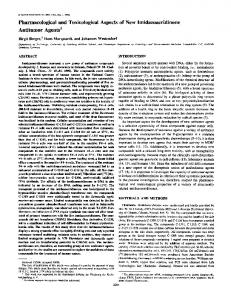
Fig. 1 a) Schematic of an MPD thruster with applied magnetic eld showing current and force components, and b) distribution of currents and j 3 B forces in the jet.
lant.16,32 As a consequence, in laboratory tests a certain (nonquanti able) impact of the ambience on thrust is generally obtained, together with a considerable impact on Isp, de ned as the ratio of thrust over fuel mass fed through the engine. This makes laboratory data on engine performance extremely doubtful. Moreover, contamination problems (material and electromagnetic) have to be seriously considered. In the following, after a short discussion of AF – MPD application potential, the nominal performance characteristics of AF – MPDs, as well as their current development status, critical areas, and unresolved problems (as seen by the authors) are described. Finally, a space experiment capable of giving the required answers is presented.
AF – MPD Thruster Application Options The installation of medium-power AF – MPD thrusters on S/C depends on the availability of suf cient power. However, future generations of satellites, like the heavy communication satellites, are planned to be provided with a source of 10 kW or more (the present preference for a large number of smaller communication satellites will not drastically change this scenario), so that power for the propulsion system, in periods when this power is not needed for the payload, is available. This opens new application elds. Spiraling-up missions for geosynchronous Earth orbit (GEO ) satellites: Spiraling-up of S/C to their destination orbit leads to large fuel savings compared with conventional positioning, which allows considerable expansion of the payload at a given overall S/C mass. These missions, however, have up to now been excluded from consideration because of the
long transfer times connected with EP. With higher power, or rather thrust, these transfer times will be reduced to an acceptable level. New studies42 show these advantages even with the thrusters with relatively low I sp. North – south-stationkeeping: For big GEO platforms the AF – MPD is better suited than other EP thrusters such as ion engines or Hall ion thrusters (SPT). This is because of the relatively simple construction and the high-thrust densities or, in the case of arcjet thrusters, because of higher Isp. Drag compensation: For large ying space structures with suf cient power installations like space stations, AF – MPDs are ideal for drag compensation, and would substantially reduce the fuel consumption and, hence, the weight, needed to reboost. Primary propulsion for deep space missions: And nally, the forthcoming high-power interplanetary missions, like a manned Mars mission, which are inconceivable without the assistance of high Isp and high-thrust propulsion, are to be considered. Here again the AF – MPD is a well-suited candidate. Table 1 summarizes in a simpli ed manner the advantages and disadvantages of the different types of EP (plasma propulsion only). For high-power missions, requiring high-velocity increments, MPD thrusters with applied magnetic eld seem to be a good choice. They possess high-thrust density, good scalability to high-power levels, and a relatively simple design. The temporary disadvantage of poor quali cation and a moderate development level will be solved, based on the vast theoretical and experimental experience already accumulated in all areas of AF – MPD technology, by the time high-power installations on S/C are available.
756
¨ LLE, AUWETER-KURTZ, AND SASOH KRU
Table 1 Thruster type
Electric propulsion thruster principles a
Propellant
Characteristics
Electrostatic: ion
Xenon (mercury )
Hall ion (stationary plasma thruster, SPT)
Xenon (krypton, argon)
Thermal arcjets
Hydrogen Hydrazine Ammonia Noble gases (hydrogen )
Self- eld MPD Applied eld MPD
High I sp (20 – 80 km/s), high ef ciency; complicated design, low-power levels 100 kW; low ef ciency High-thrust density; no neutralizer needed Medium I sp: 10 – 40 km/s; relatively simple design Power level >5 kW, easy to scale up High-thrust density; no neutralizer needed Ef ciency and lifetime to be demonstrated
Noble gases Alkali metals Hydrogen N – H compounds
Steady-state operation mode.
a
Table 2
Operation conditions and calculated thrust components of some AF – MPD thrusters 39
Thruster
B, T
mÇ , kg/s
I, A
Fhall, N
F swirl, N
Fself, N
University of Tokyo 41 Los Alamos 11 University of Osaka 38
0.10 0.19 0.075
9 3 10 27 2.5 3 1025 2.75 3 10 23
200 350 15,000
4.4 3 10 22 1.8 3 10 21 4.0
1.4 3 10 22 6.9 3 10 21 22.0
1 3 1024 9 3 1023 22.0
AF – MPD Performance Principles, Characteristics, and Technology Theoretical Basis of Operation Thrust Production
The design and acceleration principle of the AF – MPD thruster is demonstrated in Fig. 1. The thruster consists of a central cathode and a coaxial anode ring placed at the end of a nozzle-like (isolated) hardware extension. The con guration is surrounded by a magnetic coil or permanent magnet in such a way that the produced (applied) eld forms another (magnetic) kind of nozzle diverging downstream. The acceleration and energy production process is derived from the generalized Ohm’s law (for a high degree of ionization) and the corresponding energy equation j = s E* 2 vt ( j 3 B)/B
where
E* = E 1 v 3 B 1 (1/en)=pe (1)
E ? j = j 2/s 1 ( j 3 B)? v 2 (1/en)(=p e)? j
(2)
where j, s, E, B, v, e, n, and p e are the current density, scalar conductivity, electric eld, magnetic induction > magnetic eld strength, mass velocity, electron charge, electron number density, and electron pressure, respectively (vt see below). The AF – MPD theory has been treated by a variety of authors.3,11,22– 24,30,31,39 The following major mechanisms are currently known to be effective. 1) As the discharge current crosses the applied magnetic eld, azimuthal currents are induced that yield axial and radial Lorentz ( j 3 B) forces, of which the axial component directly accelerates the plasma while the radial component con nes the plasma and/or builds up a pressure hill, respectively. The magnitude of azimuthal currents (in relation to the discharge current) depends on the so-called Hall parameter, vt, where v is the cyclotron frequency of electrons, being a linear function of the magnetic induction B, and t is the collision time of electrons with heavy particles. 2) The discharge current crossing the magnetic eld simultaneously results in an azimuthal force component that puts the plasma into rotation, which is considered an important source of energy addition.11
3) Moreover, energy is added by Joule heating. 4) The self- eld ( eld produced by the discharge currrent itself) is normally negligible in the AF – MPD compared to the applied eld. All types of nondirected (rotational and thermal) energies can theoretically be converted into useful axial velocities in the mechanical and the magnetic nozzle. The latter again operates through azimuthal currents that compensate, in the ideal case, for centrifugal forces and overpressure. Judging from single particle motions, the preceding effects can be explained by the fact that electrons cannot cross the magnetic eld lines in the direction of a driving E eld except through collisions. Instead, they have a drift velocity in the direction of E 3 B which, in our geometry, corresponds to the referenced azimuthal (electron) current. In some studies, e.g., Ref. 39, dedicated thrust portions are attributed to the different acceleration mechanisms. All thrust production depending on azimuthal currents induced by the discharge current or electron pressure gradient is summarized under F hall; thrust produced through conversion of swirl motion is called F swirl; and self-magnetic thrust, if considered, is designated as F self. The rest, namely thermal or aerodynamic portions not implicitly included as of yet, may be called F therm; this summarizes the axial pressure components exerted on the mechanical nozzle. Formally, we can describe total thrust as F tot = F hall 1 F self 1 F swirl 1 F therm
(3)
Whether this simple algorithm is applicable depends, however, on the de nition of thrust portions. Quantifying each portion as being generated by the total conversion of attributed energy added, e.g., F swirl = *V ( jr B z u u ) dV ) to useful (axial) velocity, the following dependency is obtained under simplifying assumptions 40,41: F = [(F hall 1 F self)/2] 1 {[(F hall 1 F self)/2] 2 1 F 2swirl 1 F 2therm} 1/2 (4) Using this formula, one can estimate the order of magnitude of the maximum effect produced by each mechanism. Which mechanism prevails in thrust production depends on the selection of operating parameters.14,41 In Table 2 a comparison is made between the electromagnetic thrust portions for different
¨ LLE, AUWETER-KURTZ, AND SASOH KRU
cases of B, I, and mÇ that proves this statement. There is evidence that Joule heating and swirl production are energetically most relevant in the AF – MPD, with a substantial portion of the conversion taking place in the magnetic nozzle. The discharge current-equivalent mass ow mÇ equ = (m i /e)? I (single ionization), where m i is the ion mass, is far from being arrived at in known experiments,11,26,32,41 except in rare cases of light propellants. In the SPT, in contrast, currents are low and voltages are comparatively high, so that the mÇ equ requirement is met even with heavy propellants, whereas Isp is still reasonably high at the expense of low-thrust density. In the ideal case of energy gain and conversion under special consideration of rotational energy, voltage U (with a consequence to thrust F ) should relate quadratically with the magnetic eld strength B as a result of back electromotive force (EMF) produced by azimuthal velocities. This dependency is not found in the experimental results [Ref. 19, also see Eq. (5)], which is proof that those energy processes are connected with inherent losses. There are different hypotheses used to explain nonideal performance. One is that plasma viscosity plays an important role, hindering development of ideal azimuthal velocities by friction on outer (anode) walls, with velocity conversion in addition being limited by anomalous conductivity effects.22 Plasma turbulence and anomalous diffusion have a substantial in uence, which leads to very moderate effective vt30,31 [see Eq. (6) later in the text].
757
Fig. 2 Thrust as a function of discharge current and magnetic eld strength (elevated power laboratory type 39, 100 mg /s argon, p a = 3.0 Pa).
Optimization Hypotheses
As a consequence, for AF – MPD acceleration to be effective, at least a strong magnetic eld (B) of adequate shape, an optimal degree of ionization to ensure good coupling of mass to electromagnetic effects, and moderate particle density in the discharge region are required. Considering the acceleration mechanism, a lightweight propellant appears preferable for Isp gain. Applicable Propellants
In view of the need for a high degree of ionization at moderate losses, certain propellants suitable for AF – MPD engines can be considered. These are preferably easy to ionize monatomic elements: noble gases [He, Ne, Ar , (Xe)] and alkali metals15 [Li11,15,34 (Na, K)] (preferred materials are underscored), but H 2, N 2, and N – H combinations have also been used, e.g., Refs. 18, 19, 36, and 41, which suggests the capability of operating parallel to auxiliary chemical systems. The application of alkali metals is combined with considerable feed system problems and the danger of S/C contamination; the attainable tank pressure, however, is low in laboratory tests using condensable propellants that have a self-pumping effect.11 Which propellant is optimal depends on system considerations; this question may still be regarded as open.
Fig. 3 Voltage as a function of anode and cathode mass fractions (316, argon 32).
Phenomenology, Experimental Evidence
Thrust and discharge voltage generally tend to rise with the strength of the magnetic eld and the discharge current31 F and U tot ; I 0.8-1 B 0.5-1 0
(5)
(see Fig. 2 for thrust). Propellant mass ow has a more complex in uence, whereas thrust is hardly affected, i.e., only the aerodynamic part, voltage tends to go down as mass is increased, the effect depending on whether the mass is fed in the vicinity of the cathode or the anode ( ow fractions mÇ K, mÇ A).16,31,32 Thrust seems more dependent on mÇ K, whereas voltage is more in uenced by mÇ A as shown in Fig. 3. The role of mÇ A is not, or at least not primarily, to carry part of the current as an ion current, but to guarantee a certain charge carrier density in the vicinity of the anode, thus reducing anode losses and eventual strong deviation from discharge axisymmetry.27 Figure 4 gives anode losses as a function of mass distribution.29 An important phenomenon that characterizes the AF – MPD propulsion is the fact that a substantial part of the accelera-
Fig. 4 Relative anode loss as a function of distribution of supplied mass,29 thruster 313. 32
tion processes takes place outside of the hardware geometry. The discharge current, whose distribution is a function of vt (= sB/en), bulges out far downstream as B/n increases. This fact has been experimentally11,12,16,28 and computationally30,31,35 veri ed. Figure 5 shows measured current distributions at different magnetic eld strengths. According to the preceding
758
¨ LLE, AUWETER-KURTZ, AND SASOH KRU
dependency, the same applies when density decreases. This suggests the important in uence of ambient pressure as demonstrated in Fig. 6, where speci c thrust (F/I ) is shown to increase as the tank pressure and, therefore, the gas density, is reduced.12 At higher values of the critical parameter, saturation may occur. Still, environmental in uence on the overall process (participation of ambient gas) is given, leading to an uncertainty of thrust and particularly Isp determination. Even with condensable propellants this effect cannot be avoided reliably because of the wide extension of the plume and the normally moderate dimensions of the vacuum facility. In contrast, measurements have also shown 10,28 that azimuthal currents are not as high as expected from vt, which are in the magnitude of 10 – 1000. Effectively, ju / jdisch,’
Fig. 5 Distributions of discharge current (39, 500 A, 100 mg/s argon, pa = 2.0 Pa)28 at different magnetic eld strengths. B0 = a) 0.03 and b) 0.12 Vs/m 2.
B
’ vteffective ’ 3(28)
(6)
which is explained by the anomalous diffusion of electrons across the magnetic eld.6 This effect must be seriously taken into account in an assessment of AF – MPD capabilities. (This is, after all, also true for the SPT.) There are a number of consequences. For example, the magnetic nozzle is not ideally effective (cf. Ref. 22), so that the plume mass is not fully contained within boundaries given by the anode magnet lines, that is, applied eld lines passing through the anode at its widest diameter. AF – MPD thrust depends on plasma parameters and their distributions, which are a priori unknown , in contrast to electromagnetic thrust of the self-magnetic MPD thruster, which is a function of independent parameters. Consequently, computations are dif cult, as a number of far-reaching assumptions – have to be made.22 24,30,31,35,39 On the other hand, as stated earlier, the discharge current crossing the applied magnetic eld produces a torque that is (ideally) computable from independent parameters: T = Idisch B 0 (rA 2eff 2 rC 2eff)/2. As mentioned previously, it can only be partially transferred into useful thrust but has to be taken into account as a disturbance in system considerations. The typical average data for laboratory devices run at different locations are discharge current (I ) = 100 – 200 (21500 ) A; applied eld (maximum) (B 0) = 0.05 – 0.6 Vs /m 2; propellant mass ow (mÇ ) = 5 – 50 mg/s Ar, Li (He, Kr, Xe, H 2, N 2, NH 3); ambient pressure ( p a) = 10 – 0.05 (21024) Pa; discharge voltage (U) = (502) 100 – 150 V; thrust (F) = 200 – 2000 mN; speci c impulse (Isp) = F/mÇ prop = 15 – >35 km/s; and thrust ef ciency (h F) = F/(2mÇ propU ? I ) =