thesis, Routing Congestion, Congestion Estimation, Physical Design,. Placement, Physical .... aware technology mapping is NP-complete. The rest of the paper ...... http://public.itrs.net/Files/2001ITRS/Interconnect.pdf, 2001. [5] A. B. Kahng, P.
1
Technology Mapping Targeting Routing Congestion under Delay Constraints Rupesh S. Shelar, Member, IEEE, Prashant Saxena, and Sachin S. Sapatnekar, Fellow, IEEE
Abstract— Routing congestion has become a serious concern in today’s VLSI designs. To address the same, we propose a technology mapping algorithm that minimizes routing congestion under delay constraints in this paper. The algorithm employs a dynamic programming framework in the matching phase to generate probabilistic congestion maps for all the matches. These congestion maps are then utilized to minimize routing congestion during the covering, which preserves the delay-optimality of the solution using the notion of slack. Experimental results on benchmark circuits in a 100 nm technology show that the algorithm can improve track overflows by 59%, on an average, as compared to conventional technology mapping, while satisfying delay constraints. Index Terms— Technology Mapping, Physical Synthesis, Logic Synthesis, Routing Congestion, Congestion Estimation, Physical Design, Placement, Physical Synthesis
I. I NTRODUCTION A. Motivation Following Moore’s law [1], the number of on-chip transistors are doubling every two years, while the number of wires are growing almost linearly with the number of gates. This increasing design complexity results in circuits that face the problem of routing congestion, which can be described as the unavailability of a sufficient number of tracks to route wires. Moreover, wires are becoming increasingly resistive with each technology generation in spite of the advances in manufacturing techniques [2], [3], and therefore, interconnect delays have been seen to dominate gate delays since the 250 nm process technology node [4]. Together, routing congestion and the dominance of interconnect delays make timing closure extremely difficult; if wires are detoured to avoid congested regions, they may incur larger delays and thus violate timing constraints. Even worse, detours created during the routing stage invalidate the optimizations applied during earlier stages in the design flow, such as placement, that do not model detours during delay estimation. The placement and routing stages certainly offer flexibilites in terms of cell movement and detouring, respectively, to alleviate routing congestion. (See, for instance, the congestion mitigation techniques described in [5]). These flexibilities, however, are often insufficient, and are known to result in a number of design iterations, partly for the reasons stated in the previous paragraph. On the other hand, logic synthesis offers a large degree of freedom in handling the routing congestion problem, but it may suffer from inaccurate estimates as it operates at a higher level of abstraction than the placement and routing stages. In the synthesis domain, technology mapping is a powerful transformation which makes decisions about wires, and therefore, affects congestion. Consequently, it would be an excellent stage during which one could try to alleviate congestion, provided it were possible to obtain reasonably accurate congestion estimates at that stage. R. S. Shelar is with the Enterprise Microprocessors Group, Intel Corporation, Hillsboro, OR, USA. P. Saxena is with Advanced Technology Group, Synopsys Inc., Hillsboro, OR, USA S. S. Sapatnekar is with the Department of ECE, University of Minnesota, Minneapolis, MN, USA.
B. Previous Work Several technology mapping algorithms that target traditional objectives such as area, delay, or power exist in the literature [6]–[8]. Recently, there have been attempts to consider congestion during mapping. These approaches include the following: placement driven mapping for FPGA’s [9], methods employing a cost function that involves wirelength as a metric for routing congestion [10]–[12], a procedure based on predictive probabilistic congestion estimates [13], and a method based on pre-layout wirelength prediction [14]. In [9], Cong et al. present an iterative congestion-aware mapping and placement procedure for FPGA’s; however, in this work, the congestion metric used by them pertains not to routing but to cells, being defined as the number of cells placed in a given location. The approaches due to Pandini et al. [10], [11] and Stok et al. [12] rely on the total wirelength, which, being a global metric, fails to capture the locality property of the routing congestion. The work in [13] employs predictive probabilistic congestion estimates, and therefore, suffers from the inaccuracies inherent in any predictive scheme. The method of [14] employs a mutual contraction to guide the technology mapping, but suffers from the limitation that the mutual contraction, although correlating well with the wirelength, is only indirectly related to routing congestion. Other related work lies in the domain of structural logic synthesis [15], [16], where metrics for routing congestion are proposed to guide the logic synthesis. In this context, adhesion is presented as a metric for routing congestion in [15], while structural pin density is shown to correlate well with congestion in [16]. The adhesion, being computationally expensive, may not be suitable for technology mapping purposes. The structural pin density, on the other hand, ignores the congestion contribution of wires passing over a given region and therefore, may not be accurate. C. Our Contributions Considering routing congestion during the mapping is more complex than traditional objectives such as area or delay due to the following reasons. • Unlike conventional objectives, routing congestion, being locality dependent, cannot be captured using a single number at the technology mapping stage [11]. • Even with the application of a probabilistic congestion map, there is a “chicken-and-egg” problem between the mapping and placement stages, since such a congestion map is required before mapping, but cannot be created until after the placement of a mapped netlist. To overcome this “chicken-and-egg” problem, previous approaches have either used predictive congestion maps, as in [13] or have employed metrics such as wirelength or mutual contraction, as in [11], [12]. The limitation of the former approach has been the reliance on empirical data both to justify the heuristic objective function driving the mapping and to predict congestion maps for mapped netlists based solely on subject graphs, while the latter approaches attempt minimizing wirelength, assuming that it correlates well with congestion. In contrast, our current work provides a sound theoretical basis for the mapping procedure that guarantees optimal delays as
2
well as allows the use of accurate congestion maps that are created as the mapping proceeds. The contributions of this work are as follows: 1) We formulate the technology mapping problem targeting routing congestion as that of minimizing the total track overflow under the specified delay constraints. Using the dynamic programming framework, we provide a delay-optimal solution to the problem under the assumption that the placement assigned to the cells during the mapping is preserved. 2) Instead of predicting congestion from a generic netlist, such as a subject graph, and justifying its use empirically to overcome the cyclic dependence between the mapping and placement stages, we propose a matching procedure to generate two-dimensional congestion maps for all delay-optimal mapping solutions in a bottom-up manner. The procedure is general enough and can be applied not only to optimize different cost functions defined over the congestion map (such as the maximum congestion or total track overflow), but also to optimize other physical properties that can be captured using two-dimensional maps, for instance, temperature or power density maps. 3) In the covering phase, where the matches are selected from among the stored choices, we employ an explicit notion of the slack to further optimize the design unlike the classical covering approach [17], [18], which does not explore this potential. Our covering technique chooses the congestion-optimal matches that minimize the total track overflow and also satisfy the slack constraints. This technique can be easily extended to optimize even traditional objectives, such area or power under delay constraints without introducing any sub-optimality in delays. Experimental results on an entire ISCAS’85 benchmark suite confirm that delay constraints are always satisfied while improving track overflow by 59%, on an average. 4) We demonstrate that the problem of delay-driven congestionaware technology mapping is NP-complete. The rest of the paper is organized as follows. Section 2 introduces formal definitions and the background for the technology mapping problem, while Section 3 describes the generation of congestion maps during the matching phase. Section 4 illustrates the slack-constrained congestion-aware covering algorithm and Section 5 discusses the extensions to the algorithm. Section 6 presents experimental results followed by the conclusion in Section 7. We defer the proof of the NP-completeness of the delay-driven congestion-aware technology mapping problem to the Appendix. An early version of this work was presented as [19]. Since then, the work has been improved by legalizing the companion placement that has evolved in tandem with the mapping, in contrast to re-doing the placement subsequent to the mapping phase; this results in the track overflow improvement growing from the 44% reported in [19] to 59%. Furthermore, a new comparison is presented with the delaydriven congestion-aware mapping algorithm described in another recently published work, viz., [13]. The proof of the complexity of this problem presented in the Appendix is also new. II. P RELIMINARIES The following terminology is used in this paper. A Boolean network is a directed acyclic graph (DAG), in which a node denotes a Boolean function, f : B n → B, where B = {0, 1}, and n is the number of inputs to the node. Traditional technology mapping is usually preceded by a decomposition of this abstract network into one that contains primitive gates, such as 2-input NAND’s and inverters. The decomposed network is referred to as a subject graph or a premapped netlist. The subject graph is mapped on to a set of cells in the library during technology mapping; the resulting network is
known as a mapped netlist, which is placed in a given block area and routed. The block area is divided by a grid into bins for congestion analysis purposes or for global routing. Each bin contains a limited number of horizontal and vertical tracks. The track overflow and congestion can be defined for every bin as follows. Definition 2.1: The horizontal (vertical) track overflow for a given bin bin, (Th(v) ), is defined as the difference between the number of horizontal (vertical) tracks required to route the nets through the bin and the available number of horizontal (vertical) tracks. Definition 2.2: The horizontal (vertical) congestion for a given bin, bin Ch(v) , is the ratio of number of horizontal (vertical) tracks required to route the nets through the bin to the number of horizontal (vertical) tracks available. In this paper, when we use the terms “track overflow” or “congestion” without specifying a horizontal or vertical direction, we mean that the terms are equally applicable to both horizontal and vertical directions. A positive track overflow or a congestion of more than 1.0 means that sufficient tracks are unavailable for the routing, while a negative value of the overflow or a congestion smaller than 1.0 indicates the availability of tracks. The total track overflow (OF ) is the sum of positive track overflows over all the bins, as shown in the following equation OF = Σ∀bins:C bin >1.0 T bin
(1)
This overflow can be computed after the generation of the congestion map, which can be derived either using probabilistic techniques or by performing global routing. Employing these definitions, the problem of delay driven technology mapping targeting congestion can be defined as follows. Problem definition 1: Given a subject graph of a network and a library of gates, generate a mapped netlist that minimizes the total track overflow under specified delay constraints. Traditional mapping procedures use a dynamic programming framework that involves two phases, referred to as matching and covering, respectively. In the former phase, non-inferior mapping solutions are stored during a topological traversal of a circuit, while, in the latter, a mapped network is built by selecting from these solutions during a reverse topological traversal. Usually, technology mapping employs either of load-based or gain-based delay models. In this paper, we consider only load-based delay models; our algorithm can be easily extended to gain-based delay models also. The loadbased delay model is shown in Figure 1(a) for a typical standard cell: it shows a straight line with the internal delay of the gate, Dinternal , as an intercept on the delay axis, while the slope of the line indicates the effective driver resistance1 . Technology mapping targeting delay involves storing piece-wise linear load-delay curves, {(l1 , D1 ), (l2 , D2 ), · · ·}, during the matching phase, where li and Di , respectively, denote the load and delay co-ordinates of an endpoint of a piece-wise linear segment. At each node, a set of choices that are delay-optimal for the load ranges corresponding to piece-wise linear segments is stored on these curves. These choices are referred to as non-inferior matches. One such curve is shown in Figure 1(b) with three non-inferior matches M1 , M2 , and M3 , where M1 is optimal for the load range [0, l1 ], M2 for the range (l1 , l2 ], and M3 for larger load values. During the covering phase, when loads are known, delay-optimal matches are chosen from the curves. SIS [18] contains an implementation of a delay oriented mapper based on this scheme, and we employ the same framework for our technology mapping targeting routing congestion. 1 The delay of a cell also depends on the slopes of the input signal transitions, which are considered during precise timing analysis, but are often ignored in the delay models at the technology mapping stage.
3
(3, 1)
(2, 1)
(3, 2) N2 (3, 3) M1
(2, 2)
1.25
0.75
0.00
0.00
0.00
0.00
0.00
0.25
0.25
1.25
1.00 0.25
0.75
0.25
0.00
0.00
0.00
0.00
0.00
0.50
0.50
0.75
0.75
0.50
0.00
0.00
0.00
1.00
0.50
0.00
0.00
0.25
0.25
1.00
0.75
0.25
N1 (1, 1)
(1, 2)
(1, 3) N3
(a)
(b)
(c)
(d)
(e)
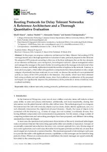
Fig. 3. Generating congestion maps during the matching: (a) A choice M1 at node N1 . Maps for horizontal congestion for matches at N2 and N3 are shown in (b) and (c), respectively, while (d) shows congestion contribution due to M1 and (e) shows the congestion map at N1 due to M1 .
Delay
Delay
M2
M3
M1
Rdriver
Dinternal
Load (a)
l1
l2 Load (b)
Fig. 1. (a) A load-based delay model for a typical standard cell, such as an inverter. (b) A typical load-delay curve stored during the matching.
Terminal 2 0.5
1.5
0.5
1.0
1.0
0.5
0.5
1.0
1.0
0.5
2.5
1.5
2.5
1.5
III. C ONGESTION M AP G ENERATION DURING THE M ATCHING P HASE
Route 4
The matching phase of dynamic programming based delay oriented technology mapping typically involves storing a load vs. delay curve at each node. We employ the same method and preserve the curve containing non-inferior matches that minimize the delay for different load values. During the construction of the curve, wire-loads and wire-delays are accounted for based on the companion placement of the underlying subject graph. To evaluate different mapping solutions based on their contribution to the total track overflow, we associate a probabilistic congestion map with each match. This congestion map represents wires due to the mapping solution corresponding to a given match, as explained in the following subsections.
Route 5
A. Bottom-up Congestion Map Construction
Route 1 Route 2 Route 3
1.5
associated with each bin show the demands for the horizontal tracks. For instance, the leftmost bin in the bottom row has a demand of 1.5, since there are three routes, route 1, 5, and 6, which require half track each in that bin. Therefore, the congestion for the bin due to 1.5 , where, hbin is the number of horizontal tracks the net is 6×h bin available for the bin.
0.5 Route 6
Terminal 1 Fig. 2. Probabilistic congestion estimation for a net assuming only L- and Z-shaped routes [20]. Only the demands for horizontal tracks in each bin are shown.
The concept of employing a companion placement for the subject graph to estimate wirelengths or congestion maps is not new. It has been used by previous technology mapping or physical synthesis methods [11]–[13], [17], [21], and we employ the same concept here. Based on such a companion placement, the congestion maps are generated during the matching phase employing a well known probabilistic method, which is shown to have a good fidelity with post-routing congestion in [20], [22]. The probabilistic estimation technique assumes all routes to be equally possible for a given net and then computes the demands for tracks as a ratio of the number of paths passing through the bin to the total number of paths. Figure 2 shows the congestion computation for a net. Six possible paths, assuming only L- and Z-shaped routes2 , through different bins in the bounding box of a net are shown in the figure. The numbers 2 L- and Z-shaped routes are shown for illustration purposes only. In practice, we allow the nets to have unlimited bends, as in [22].
To generate a global as well as a partial view of congestion, we propose a bottom-up congestion map construction. A match at a given node is assumed to be placed at the center of gravity of its fanins and fanouts (whose locations are available from the companion placement), and multi-terminal nets are modeled employing the well known star topology. Figure 3 shows the creation of a congestion map for a match M1 at the node N1 . The match M1 receives its inputs from two nodes: N2 and N3 . During the topological traversal, these nodes are processed before node N1 and hence, non-inferior matches and the corresponding congestion maps are already stored at these nodes. The maps of horizontal congestion for matches at N2 and N3 that minimize the delay for the solution due to the match M1 are shown in Figure 3(b) and (c), respectively, while the horizontal congestion contribution due to the match M1 is shown in 3(d). For the purposes of illustration, only the track demands are shown as congestion without loss of generality. In Figure 3(d), the right-most bin in the third row has a horizontal track demand of 0.25, as there are 2 paths from the output of the match at N2 to an input of M1 . This results in a probability of 21 of the path through the bin being selected. Furthermore, for that path, only half of one horizontal track is occupied under the assumptions of probabilistic congestion estimation [22], resulting in a demand of 0.25. Figure 3(e) shows the map for horizontal congestion for the solution involving the match M1 : it is obtained by the simple bin-wise sum of the congestion maps at N1 , N2 , and N3 . Thus, for instance, the demands in bin (1, 2) in the congestion maps in figures 3(b), (c) and (d) are added to create the
4
0.2
0.6
0.4
0.6
0.8
0.4
0.2
0.2
0.2
0.1
0.3
0.2
0.3
0.4
0.2
0.1
0.1
0.1
N3 N1 N2 Fig. 4. The congestion in each bin is divided by the number of fanouts for forward propagation.
demand in bin (1, 2) in the congestion map shown in Figure 3(e). This congestion map represents horizontal track demands due to the subset of wires from the transitive fanin cone of N1 , as these wires appear in the mapping solution corresponding to the match M1 . For a different match at node N1 , this subset of wires will be different leading to a different congestion map. Note that these congestion maps account for the relevant subsets of wires from only the transitive fanin cone of a given node, ignoring wires in the rest of the network. Thus, they do not represent a global picture of congestion; rather, they represent a partial picture that accounts only for the matches and corresponding wires in the transitive fanin cone of a given node. It is clear that a complete picture of congestion that represents all the wires that will appear in the mapped network cannot be obtained until matching and bottom-up congestion map generation is performed for all the nodes. This is the reason why we postpone the total track overflow computation until the covering stage. B. Handling Multiple Fanouts For the multiple fanout points, as shown in Figure 4, the congestion in each bin is divided by the number of fanouts. It allows the construction of the congestion map for the solutions at primary outputs by simply carrying out the bin-wise sum of the corresponding congestion maps. This heuristic is similar to the one employed in [7] for the area minimization under delay constraints, where in spite of such a division of gate-areas at multiple fanout points, addition of the gate-areas due to points on area-delay curve at primary outputs generates the gate-area for an entire solution. Thus, employing simple algebraic operations such as addition and multiplication, two-dimensional congestion maps can be created during the matching phase. These maps can be used to optimize any cost function defined on them, for instance, total track overflow or maximum congestion. Moreover, the entire technique to generate congestion maps is quite general and can be applied to create twodimensional maps for even other physical properties, such as power density. C. Analogy with Classical Matching The bottom-up congestion map generation is analogous to the work in [7], where area minimization under delay constraints is sought. However, in contrast, our work targets routing congestion under the same constraints, rather than the area as in [7]. The partial congestion maps during the matching in our work correspond to gate-areas for points on the area-delay curve in [7]. Just as the gate-area for a point on the curve models the corresponding gate-areas due to the match at a given node and its transitive fanin cone in [7], the congestion map for a match at a given node accounts for wires due to matches in the
transitive fanin cone and represents the corresponding probabilistic congestion of these wires in our work. Just as the gate-area for entire network cannot be predicted until the end of the matching phase in [7], so is the inability of the dynamic programming framework in our work to predict the congestion map of entire network until the end of the matching. Of course, compared to a metric like gate-area, the routing congestion optimization objective is far more complicated, as noted in several recent works [11], [13], [15], [16]. We also employ a better delay computation approach as compared to [7]. In their work, the construction of area-delay curves introduces sub-optimality due to unknown loads in the matching phase. In contrast, we store noninferior solutions using piece-wise linear load-delay curves, which serves the following purposes. 1) It does not introduce any sub-optimality in delays due to the load computation and therefore, allows one to generate a delayoptimal solution. 2) Because of the ability to generate a delay-optimal solution, it ensures that if the delay-optimal solution cannot meet constraints, no other solution can. Moreover, we utilize the companion placement to account for wireloads and wire-delays, which are ignored in their work. D. Comparison with Other Congestion-aware Matching Techniques The matching procedures employed in previous approaches on congestion-aware mapping either compute the wire-length, as in [10]– [12], or the congestion cost based on probabilistic estimates, as in [13]. The following are the limitations of these approaches. 1) All these approaches heuristically modify the area or delay cost function by adding wirelength or congestion penalty terms. This introduces sub-optimality in the estimation of these objective functions, and therefore, none of these approaches can ensure meeting area or delay constraints (under the usual assumptions about delay models and placement fidelity) while minimizing routing congestion. 2) As pointed out earlier, metrics such as wirelength and predicted congestion may not capture an accurate picture of the congestion. These limitations are overcome easily by our matching procedure, which stores all non-inferior matches along with their probabilistic congestion maps that are constructed using simple algebraic operations such as addition and multiplication in a bottom-up manner. Moreover, although the metrics proposed in previous approaches have been applied during the matching phase, none of them extends these metrics to guide the covering, which actually selects the mapping solution. Thus, these techniques ignore the search space available during the covering. In contrast, we utilize the generated congestion maps during the covering process to compute the total track overflow due to different mapping choices, and to select the one that minimizes this track overflow while satisfying the delay constraints. This is explained in the following section. IV. C ONGESTION M INIMIZATION UNDER D ELAY C ONSTRAINTS DURING THE C OVERING P HASE To preserve the delay-optimality of the solution while improving the congestion, we associate the usual notion of a slack with all nodes. Definition 4.1: The slack at a given node is the difference between the required arrival time at that node and the actual arrival time. A positive value of slack means that the signal arrives earlier than the required arrival time, while a negative value implies that it arrives later than the required time. During traditional covering, delay-optimal choices that minimize the delay for a given load are
5
chosen at each node. The load-delay curves that are built during the matching phase also assume the same. We observe that the covering need not choose delay-optimal choices at all nodes to respect the delay constraints. At nodes with positive slack, matches that are not necessarily delay-optimal can still be chosen, as long as they meet the delay constraints. Our covering algorithm employs this idea to minimize the total track overflow. We explain the same using the following example. M3
Delay M1
50
M2 2
1
3
10
20
Load
Fig. 5. A piece-wise linear load-delay curve with three matches matches M1 , M2 , and M3 optimal for load ranges [0, 10), [10, 20), and [20, ∞), respectively. The curve has a slope of 3 for the load values [0, 10), a slope of 2 for loads between [20, 30), and a slope of 1 for remaining load values.
Consider a load-delay curve, shown in Figure 5, stored during the matching for a node. During the covering, when the node is processed, let us assume that that it has a slack of 10 and it has to drive a load of 15. Let the delays due to matches M1 , M2 , and M3 for this load be, respectively, 95, 90, and 95. In this case, regular covering will choose match M2 , since it minimizes the delay, while our congestion-aware covering will choose a match that minimizes the track overflow. Note that choosing M1 or M3 does not affect the delay-optimality of the overall solution in this case, since there is a slack of 10 at the node, and the arrival times at the node due to both M1 and M3 , satisfy this slack constraint. A. Algorithm for the Covering The pseudo-code for the covering that targets track overflow under delay constraints is shown in Algorithm 1. It begins with the computation of the delay-optimal matches at the primary outputs. The slacks (Soi ) are then computed for all the outputs. The congestion map CM for this solution is built by the bin-wise addition of the congestion maps due to delay-optimal matches for all the primary outputs. This congestion map represents the contributions of all the wires that will appear in the mapped network due to the conventional delay-optimal solution. The total track overflow OF corresponding to this solution is estimated from the congestion map using Equation (1). After this initialization, all the nodes (v ∈ V ) are processed in the reverse topological order. First the delay-optimal match mD−optimal v is determined for a node, followed by a computation of the slackusing a procedure constrained congestion-optimal match mC−optimal v that is explained later. If the overflow OFvC−optimal due to the slackconstrained congestion-optimal match mC−optimal is smaller than v that due to the delay-optimal match mD−optimal , then mC−optimal v v Optimal is chosen as the optimal match mv . In this case, the congestion map is updated to reflect the change due to this match, the new overflow is stored, and the slacks at the inputs of the match are also updated. Instead, if the delay-optimal match is chosen as the optimal match mOptimal , then the slack is simply propagated to the inputs v of the match. Finally, the loads at the inputs of the selected optimal match (be it delay-optimal or slack-constrained congestion-optimal) are incremented to reflect the selection of that match.
Algorithm 1 Perform the covering targeting congestion minimization under delay constraints Input: A Boolean network G(V, E), a set of primary outputs O ⊆ V , sets of non-inferior matches Mv and their congestion maps CMv for v ∈ V Output: Assignment of congestion-optimal match m ∈ Mv to v ∈ V , which satisfies the delay constraint 1: for ∀oi ∈ O do ← DelayOptimalMatch(Moi , loadoi ) 2: mD−optimal oi − DmD−optimal 3: Soi ← DoRequired i oi 4: end for P |O| 5: CM ← CMmD−optimal i=1 oi 6: OF ← ComputeOverflow(CM ) 7: for ∀v ∈ V , in reverse topological order do 8: mD−optimal ← DelayOptimalMatch(Mv , loadv ) v 9: mC−optimal ← CongestionOptimalMatch(Mv , sv ) v 10: if OFvC−optimal < OF then 11: mOptimal ← mC−optimal v v 12: CM ← CM − CMmD−optimal + CMmC−optimal v v 13: OF ← OFvC−optimal 14: UpdateSlacks(mC−optimal , sC−optimal ) v v 15: else 16: mOptimal ← mD−optimal v v 17: UpdateSlacks(mD−optimal , sv ) v 18: end if 19: IncrementLoads(mOptimal ) v 20: end for
B. Procedure for Finding Slack-constrained Congestion-optimal Match The pseudo-code for selecting the slack-constrained congestionoptimal match is shown in Algorithm 2. It considers all the matches except the delay-optimal match such that they satisfy the slack constraint (as enforced in line 6 in the pseudo-code). Among these matches, one that results in the lowest total track overflow is stored as the slack-constrained congestion-optimal match. Note that we can store a match that results in the smallest maximum congestion as a congestion-optimal one, leading to the optimization of the maximum congestion. In general, any cost function defined over the congestion maps can be optimized by storing a match that optimizes the given objective as a congestion-optimal match. The corresponding slack updates are maintained with the congestion-optimal match. If the track overflow due to this match is lower than that due to the delayoptimal match, then the slack-constrained congestion-optimal match is stored as the optimal match, as described earlier. C. Time Complexity of the Algorithm The time-complexity of the entire mapping algorithm is almost same as that of a conventional mapping. Both conventional as well as our congestion-aware mapping techniques employ the same matching procedure, except that the matching phase in our case computes and stores congestion maps for non-inferior matches. If there are NBins number of bins in the layout, then the matching phase would require O(NBins Nmatches ) time (where NM atches is the number of noninferior matches over the entire network), since the computation of a congestion map requires O(NBins ) time. Since NBins is a constant , the matching phase for our approach requires O(Nmatches ) time for a given layout. Note that although NBins is possibly large as compared to other constants subsumed by O(), the actual number of bins impacted during the generation of a match (and hence their
6
Algorithm 2 Find congestion-optimal match that satisfies the slack constraint Input: A set of matches Mv for v and available slack sv at node v Output: Congestion-optimal match satisfying the slack and the corresponding total track overflow OFvC−optimal 1: Procedure CongestionOptimalMatch(Mv , sv ) { 2: OFvC−optimal ← ∞ 3: if sv > 0 then 4: for all m ∈ Mv − mD−optimal do v 5: Dmv ← DelayDueToMatch(loadv ) 6: if Dmv − DvD−optimal < sv then 7: CMnew ← CM − CMmD−optimal + CMm v 8: OFnew ← ComputeOverflow(CMnew ) 9: if OFnew < OFvC−optimal then 10: OFvC−optimal ← OFnew 11: mC−optimal ←m v 12: sC−optimal ← sv − (Dmv − DmD−optimal ) v v 13: end if 14: end if 15: end for 16: end if 17: }
contribution to the time complexity) is usually much smaller. During the covering, CongestionOptimalMatch() function is called for all the nodes. The function requires O(|Mv |NBins ) time, since, in the worst case, it has to consider all the matches at the node to find the slackconstrained congestion-optimal one. Over all the nodes, therefore, the covering requires O(Nmatches ) time, which is same as that of the matching phase. V. N OTES ON C ONGESTION O PTIMALITY AND E XTENSIONS TO THE A LGORITHM The mapping algorithm can preserve the delay optimality of a solution under the usual assumptions about the delay model and placement fidelity, but it does not ensure the optimality of the track overflow. In other words, the resulting congestion may not be the minimum, although it will usually be much smaller than that obtained using conventional mapping, for given delay constraints. This is a consequence of the routing congestion being more complex an objective than the traditional ones, such as area and delay. The dynamic programming based matching and covering procedures may not be able to generate the congestion optimal solution in polynomial time. The Appendix contains a proof for the NP-completeness of the mapping aimed at minimizing congestion under delay constraints. Our algorithm, which is based on the load-based delay model, can be easily extended to the one based on gain-based delay model. Note that during technology mapping based on the gain-based delay model, the sizes of the cells are adjusted depending on the loads that they drive, and this does not affect the wires and hence, the computed routing congestion in the design under the assumptions about the placement of cells. The extension of our tree-mapping algorithm to a DAG-mapping one, such as [8], is, however, not obvious because of the duplication of wires due to the corresponding replication of the underlying logic gates. In our current implementation, we do not store matches that are potentially good from the congestion standpoint, but have possibly inferior delay characteristics. Consequently, we do not minimize the congestion to the fullest extent possible. This can be remedied by storing a few inferior matches apart from those on the regular load-delay curve, at the cost of extra computation and memory. The memory requirement of our mapper is larger than that for a conventional
mapper due to the storage of congestion maps for all non-inferior choices during the matching phase. This requirement may be reduced by storing just the bins corresponding to the bounding box that is affected by the mapping solution. Moreover, a memory efficient variant of our algorithm having the same memory capacity as that of conventional delay oriented mapping is possible by restricting the selection of the congestion-optimal matches to the primary outputs. In such a variant, the congestion maps for all non-inferior matches at all nodes except for the primary outputs are not required after the maps for the matches for the subsequent nodes in the topological order are computed during the matching phase. Hence, the memory occupied by the corresponding congestion maps that have served the purpose of the forward propagation can be freed and re-used. We expect our current mapper to be used in an engineering change order (ECO) mode, where at most a few thousand cells corresponding to the congestion hot-spots are (re-)synthesized. It is an ideal candidate for such an application, since it ensures that delay constraints will be met while minimizing total track overflow. This is demonstrated by the experimental results in the following section, which shows that circuits with more than 3500 cells can be handled well by our algorithm without needing recourse to memory efficient variants. VI. E XPERIMENTAL R ESULTS A. Experimental Setup The congestion-aware mapping algorithm is implemented in C and incorporated in SIS [18]. We performed experiments on the entire3 set of ISCAS’85 benchmarks employing the design flow shown in Figure 6. For a given benchmark, the subject graph containing primitive gates is placed to create the companion placement. This is followed by either the conventional or our congestion-aware mapping algorithm. For a fair comparison, the conventional delay oriented technology mapping algorithm in SIS [18] is modified to use the companion placement information to compute wire-loads and wiredelays, as our congestion-aware technology mapping utilizes the same information not only for the bottom-up congestion map generation but also for the wire-load and wire-delay computation. After the technology mapping, the resulting netlists are placed and routed. For all the experiments, technology mapping is performed employing lib2.genlib library in SIS, which is characterized for 100 nm technology [23] and contains up to 4 strengths for each cell. To generate delay constraints for a given benchmark, conventional technology mapping is run first and the delay of the most critical primary output is assigned as the required arrival time for all primary outputs. For the placement, we employ the publicly available recursive bisectioning based placer Capo [24], while, for routing, we use a router [25] that is based on non-Hanan routing. In the case of our technology mapping targeting routing congestion, we legalize the placement of the mapped netlist employing the legalizer PlaceUtil-Lnx32.exe from the Gigasscale Silicon Research Center (GSRC) Bookshelf [26]. Recall that the matches in the mapped netlist are placed at the center of gravity of fanins and fanouts based on the subject graph placement. Such a placement of the mapped netlist, however, may not be legal, thus requiring overlap removal. The placement legalization instead of whole new (re-)placement of the mapped netlist preserves most of the gains obtained during the technology mapping. The post-routing delays are measured using a static timing analyzer. B. Analysis of Experimental Results Table I shows the comparison of post global routing results due to conventional mapping as well as our mapping. It shows the block 3 The results on the smallest benchmark from the ISCAS’85 suite, C17, are not shown, as its implementation requires only a few gates, becoming an un-interesting case to show meaningful comparison.
7
Example
Area
Conventional [18] / Ours Delay MC RU # of cells Run-time µ2 ps % s C1355 3439 227 / 134 (40) 789 / 786 1.70 / 1.30 80 / 81 621 / 592 11 / 12 C1908 3616 323 / 63 (80) 1059 / 1042 1.70 / 1.10 80 / 80 578 / 571 12 / 13 C2670 11707 417 / 139 (66) 1258 / 1240 1.65 / 1.20 75 / 77 1482 / 1426 24 / 51 C3540 25994 1078 / 194 (82) 1655 / 1632 2.25 / 1.25 75 / 80 3254 / 3105 90 / 279 C432 1962 66 / 45 (31) 854 / 842 1.40 / 1.10 80 / 82 264 / 311 7/9 C499 3550 262 / 80 (69) 823 / 821 1.60 / 1.20 80 / 79 595 / 563 11 / 13 C5315 17265 1100 / 289 (73) 1120 / 1114 2.20 / 1.40 75 / 77 2122 / 2131 38 / 121 C6288 21379 515 / 452 (12) 4771 / 4731 1.70 / 1.40 80 / 80 3737 / 3596 88 / 135 C7552 28223 1343 / 547 (59) 1341 /1309 1.60 / 1.30 75 / 73 3198 / 3080 132 / 213 C880 3944 378 / 67 (82) 890 / 884 1.70 / 1.20 80 / 76 584 / 575 12 / 13 Average 554 / 201 (59) 1455 / 1439 1.74 / 1.24 78 / 78 164 / 159 42 / 85 TABLE I C OMPARISON OF THE CONVENTIONAL MAPPING WITH OUR ALGORITHM . ‘RU’ AND ‘MC’ DENOTE THE AVERAGE ROW UTILIZATION AND MAXIMUM CONGESTION , RESPECTIVELY. Overflow
Subject Graph
(% gain)
I/O Locations
Placement
3) Technology Mapping
Placement/ Legalization
4)
Routing
Timing Analysis Fig. 6. mapping
Design flow for conventional and congestion-aware technology
area in Column 2 for the benchmarks in Column 1, while Columns 3, 4, 5, 6, 7, and 8 show the total track overflow (with the improvement percentage), the delay, the maximum congestion, the average row utilization, the number of cells, and the run-time, respectively. All the experiments are run on a Sun Ultra Sparc 60 machine with 400 MHz clock speed. From the table, we can observe the following: 1) Our mapping algorithm has been consistently able to reduce the track overflow, as shown in Column 3. On an average, the reduction is 59%. The large gains can partly be attributed to the legalization-based flow. Since most of the companion placement of the mapped netlist is preserved because of the legalization, the gains obtained during the technology mapping are preserved. The impressive gains in overflow also underline the ability of the technology mapping to reduce the congestion. The largest improvement, 82%, is in the case of C3540 and C880, while the smallest one is in case of C6288. The small improvement in case of C6288 can be attributed to the relatively lower congestion in the design as compared to other benchmarks of a similar size. 2) From Column 4, it is clear that the delays due to congestionaware mapping have improved slightly, as the algorithm maintains the delay-optimality, resulting in the same delays as
5)
6)
the conventional mapping. The subsequent stages, especially the routing, show the effect of reduced congestion, causing smaller detours and hence, smaller delays as compared to the conventionally mapped netlists. The maximum congestion shown in Column 5 has improved due to our mapping in all the cases with an average improvement of 28%, even though the algorithm targets only the total track overflow. This can be ascribed to the correlation between the maximum congestion and the total track overflow: generally, high overflow implies the large maximum congestion and vice-versa. It appears from Column 6 that the average row utilization has increased, as in cases of C2670 and C3540, and has also decreased, as in cases of C7552 and C880, with the track overflow. This can be attributed to the corresponding increase or decrease in the cell area. Depending on the context, an area increase or decrease can result in a small track overflow: an example in [13] shows that even an area optimal match, which results in a relatively smaller area, can worsen the congestion, while it is also possible that an increase in area due to more gates, and hence, more wires, proves detrimental to the objective of reducing the congestion. This is why the congestion is relatively insensitive to the average row utilization, as long as the utilization is not too high. As shown in Column 7, the number of cells in the congestionaware mapped netlists have decreased slightly in all cases but that of C432. The decrease in the number of cells can be associated with the corresponding reduction in the number of nets, which may be indirectly correlated with metrics such as structural pin-density, and hence, congestion, as pointed out in [16]. In case of C432, however, employing more logic cells has resulted in the congestion alleviation, which can be explained using the discussion in the previous remark on the average row utilization. Finally, as can be seen from Column 8, the run-times for congestion-aware mapping are still comparable to those of the conventional one. On an average, although the run-time is 2.02 times worse than that for conventional mapping, it is still practical, being within a few minutes on a 400 MHz Sun Ultra Sparc machine. This shows that the constants subsumed by O() in the time complexity expression in Section IV-C are not too large. This bodes well for the scalability of the algorithm.
8
C. Comparison With Previous Work Table II shows the comparison of this work with the previous congestion-aware technology mapping approach [13]. Columns in the table have the same meanings as in Table I. The following observations can be made from the table. 1) From Column 2, it is evident that as compared to the congestion-aware technology mapping in [13], our approach results in 30% improvement, on an average. This can be attributed to the following: (a) as opposed to the the work in [13], which relies on the same predictive congestion map based on subject graph for all matches, we create match-specific congestion maps in a bottom-up manner that are more accurate; (b) our approach exploits slacks to the fullest extent, while, in the previous approach, a global constant is employed to weight the paths according to the slack at the primary outputs; and (c) instead of re-placing the mapped netlist as in [13] (or even in [19]), we legalize the existing companion placement of the netlist, which preserves the overflow gains achieved during the mapping. 2) It is clear from Column 3 that the delays due to our mapping algorithm are slightly worse than those due to the congestionaware technology mapping in [13]. This occurs because our algorithm exploits slack to a greater extent than their method as explained earlier. Note that delays in both the cases still satisfy the required delay constraints obtained from conventional mapping shown in Table I. 3) Column 4 shows that the maximum congestion due to our mapping is either the same or smaller than that due to the previous work. This can be ascribed to the (weak) correlation between track overflow and maximum congestion: small track overflow due to our mapping also implies relatively less maximum congestion. 4) From Column 5, we observe that for large examples, runtimes for our mapping are worse than that for the congestionaware mapping. This is due to the additional book-keeping our algorithm has to perform to generate congestion maps in a bottom-up manner. For small examples, the run-time for extra topological traversal in the algorithm of [13] dominates that for the generation of congestion maps; this is the reason why we see the relatively smaller run times for our mapping on the small benchmarks. We could not compare the results on ITC’99 benchmarks, such as b14, b15, and b20, reported in [13], since the applicability of our mapper on Sun Ultra Sparc 60 machine, which is employed to run the mapper, is limited to approximately 5000 cells. In future, we plan to implement the memory efficient variant of our algorithm. Example
Congestion-aware technology mapping [13] / Ours Overflow Delay MC Run-time ps s C1355 173 / 134 774 / 786 1.50 / 1.30 13 / 12 C1908 87 / 63 1065 / 1042 1.10 / 1.10 14 / 13 C432 54 / 45 840 / 842 1.40 / 1.10 8/9 C499 188 / 80 791 / 821 1.20 / 1.20 12 / 13 C6288 474 / 452 4682 / 4731 1.40 / 1.40 117 / 135 C7552 743 / 547 1255 /1309 1.80 / 1.30 203 / 213 C880 270 / 67 867 / 884 1.40 / 1.20 17 / 13 Average 284 / 198 1467 / 1487 1.40 / 1.22 54 / 58 TABLE II C OMPARISON OF THE CONGESTION - AWARE TECHNOLOGY MAPPING [13] WITH OUR ALGORITHM . ‘MC’ DENOTES THE AVERAGE ROW UTILIZATION AND MAXIMUM CONGESTION , RESPECTIVELY.
The comparison with the competitive congestion-aware delay oriented mapping approaches [11], [12] could not be performed because of the unavailability of the access to proprietary benchmarks and tools, while another relevant work on congestion-aware technology mapping [14] targets area of the circuit and not the delays. VII. C ONCLUSION In this paper, we have presented a technology mapping algorithm targeting routing congestion. We have shown how to overcome the “chicken-and-egg” problem during the mapping and placement stages by generating and propagating congestion maps associated with each choice during the matching phase. We have proposed a covering procedure, which exploits slacks to select the congestionoptimal choices that preserve the delay-optimality of the solution, followed by a legalization of the companion placement. The experimental results on ISCAS’85 benchmarks prove the efficiency of the algorithm, as they show, on an average, 59% improvement in the track overflow as compared to conventional mapping. The impressive gains in the track overflow emphasize the ability of the technology mapping to reduce the routing congestion. The proposed matching and covering techniques are sufficiently general and can be applied to optimize different cost functions defined on congestion maps as well as different physical properties, which can be captured employing two-dimensional maps, such as power-density maps. A PPENDIX Complexity of Delay-driven Congestion-aware Mapping The Minimum Clique Cover [27] is a known NP-complete problem that is defined as follows: Given an instance of an undirected graph G = (V, E) and a positive integer K, does there exist a clique cover for G (i.e., a collection V1 , V2 , ., Vk of subsets of V such that each Vi induces a complete subgraph of V and such that for each edge (vi , vj ) ∈ E, ∃m such that vi , vj ∈ Vm ) with cardinality k ≤ K ? We reduce this problem to an instance of the decision version of the delay-driven congestion-aware technology mapping problem as follows. Let V = v1 , v2 , ., vn be the vertices of G. We associate a Boolean variable xi with the vertexP vi (i = 1, ., n) and generate the (xi ⊕ xj ). Our goal Boolean function fG (x1 , ., xn ) = (vi ,vj )∈E is to map this function using a pre-specified cell library and then to place it in the left half of a rectangular region that contains each of the literals xi and xi (i = 1, ., n) as primary input pins on its left boundary and a primary output pin corresponding to the computed function in the middle of its right boundary. Furthermore, the right half of the placement region contains a pre-placed macro block that computes the logical or (“+”) of up to n(n − 1)/2 inputs (by tying unused inputs to 0); the output of this macro block is connected to the primary output pin. Our cell library P consists only P of gates that implement the functions gp (u1 , ., up ) = ( i=1,.,p ui )( i=1,.,p ui ), for p = 2, ., n. Finally, we assume that the number of routing tracks available to hook up the mapped netlist in the left half of the placement region to the inputs of the macro block in the right half of the placement region is K, and the delay constraints are such that any path from a primary input to an input of the macro block can pass through no more than one gate. Firstly, observe that the size of the function fG (x1 , ., xn ) as specified above is linear in the number of edges in G. Next, for any clique H with vertices w1 , ., wr and corresponding Boolean variables y1 , .,P yr respectively, it P is easy to see that gr (y1 , ., yr ) = P ( i=1,.,r yi )( i=1,.,r yi ) = (y y + yi yj ) = (wi ,wj )∈E(H) i j P (y ⊕ y ) = f (y , ., y ). However, if H is not a j H 1 r (wi ,wj )∈E(H) i clique, the above equality does not hold. (If edge (wi , wj ) is missing from E(H), then yi yj , yi yj ∈ gr (y1 , ., yr ) − fH (y1 , ., yr )). Finally,
9
one can verify that for two cliques Kr1 and Kr2 with r1 and r2 vertices respectively, fKr1 ∪Kr2 = g|V (Kr1 )| + g|V (Kr2 )| (with the three functions being defined over the Boolean variables corresponding to the vertices of Kr1 ∪ Kr2 , Kr1 and Kr2 , respectively, where the union G1 ∪ G2 of two graphs G1 and G2 is defined as the unions of their corresponding vertex and edge sets, respectively); this equality holds irrespective of whether the vertex sets of the two cliques are disjoint or share an arbitrary P number of vertices. By induction, this property (viz., f∪j Krj = j g|V (Krj )| ) extends to the unions of the vertex sets of an arbitrary number of cliques. Thus, there is a bijection between a clique Ki in G and a gate implementing the function g|V (Ki )| . Furthermore, this correspondence can be extended to any set of cliques in G by mapping them to the “+” of the corresponding g functions. Given the delay constraint that does not permit us to map to two or more g-gates in series and the fact that no g-function is equivalent to a “+” function, a set of k cliques corresponds to a mapping into k gates whose outputs feed into the “+” macro block, resulting in a usage of exactly k tracks. In particular, a clique cover of G of cardinality k corresponds to a mapping solution that uses k tracks. Conversely, given a mapping solution that uses k′ tracks, one can construct a clique cover of cardinality k′ by mapping each of the gates in the mapping solution to its corresponding clique. This concludes the proof that the decision version of the delay-driven congestion-aware technology mapping problem (and, in particular, its covering phase) is NP-hard. To complete the proof of its NP-completeness, it suffices to observe that, given a mapping, one can run a polynomial static timing analysis on it to determine whether it meets the required delay constraints, as well as construct a probabilistic congestion map (or run a global router) on it in polynomial time to determine whether it meets the congestion constraints. R EFERENCES [1] G. E. Moore, “Cramming more components onto integrated circuits,” in Electronics, pp. 114–117, Apr. 1965. [2] P. Saxena, N. Menezes, P. Cocchini, and D. A. Kirkpatrick, “Repeater scaling and its impact on CAD,” IEEE Trans. CAD, vol. 23, pp. 451–463, Apr. 2004. [3] P. Kapur, G. Chandra, and K. C. Saraswat, “Power estimation in global interconnects and its reduction using a novel repeater insertion methodology,” in Proc. DAC, pp. 461–466, June 2002. [4] “International technology roadmap for semiconductors, 2001 edition: Interconnect.” http://public.itrs.net/Files/2001ITRS/Interconnect.pdf, 2001. [5] A. B. Kahng, P. Rodman, and P. Villarubia, “Physical chip implementation methodology: Hot spots and best practices.” Tutorial at ACM/IEEE Design Automation Conference, June 2002. Available at http://vlsicad.ucsd.edu/˜abk/TALKS/. [6] K. Keutzer, “DAGON: Technology binding and local optimization by DAG matching,” in Proc. DAC, pp. 341–347, June 1987. [7] K. Chaudhary and M. Pedram, “A near optimal algorithm for technology mapping minimizing area under delay constraints,” in Proc. DAC, pp. 492–498, June 1992. [8] Y. Kukimoto, R. K. Brayton, and P. Sawkar, “Delay-optimal technology mapping by DAG covering,” in Proc. DAC, pp. 348–351, June 1998. [9] J. Y. Lin, A. Jagannathan, and J. Cong, “Placement-driven technology mapping for LUT-Based FPGA’s,” in Proc. ISFPGA, pp. 121–126, Feb. 2003. [10] D. Pandini, L. T. Pileggi, and A. J. Strojwas, “Congestion aware logic synthesis,” in Proc. DATE, pp. 664–671, Mar. 2002. [11] D. Pandini, L. T. Pileggi, and A. J. Strojwas, “Global and local congestion optimization in technology mapping,” IEEE Trans. CAD, vol. 22, pp. 498–505, Apr. 2003. [12] L. Stok and T. Kutzschebauch, “Congestion aware layout driven logic synthesis,” in Proc. ICCAD, pp. 216–223, Nov. 2001. [13] R. Shelar, S. Sapatnekar, P. Saxena, and X. Wang, “A predictive distributed congestion metric with application to technology mapping,” IEEE Trans. CAD, vol. 24, pp. 696–710, May 2005.
[14] Q. Liu and M. Marek-Sadowska, “Wirelength prediction-based technology mapping and fanout optimization,” in Proc. ISPD, pp. 145–151, Apr. 2005. [15] P. Kudva, A. Sullivan, and W. Dougherty, “Metrics for structural logic synthesis,” in Proc. ICCAD, pp. 551–556, November 2002. [16] Q. Liu and M. Marek-Sadowska, “Pre-layout wirelength and congestion estimation,” in Proc. DAC, pp. 582–587, June 2004. [17] M. Pedram and N. Bhat, “Layout driven technology mapping,” in Proc. DAC, pp. 99–105, June 1991. [18] E. M. Sentovich, “SIS: A system for sequential circuit synthesis.” Memorandum No. UCB/ERL M92/41, May 1992. [19] R. Shelar, S. Sapatnekar, P. Saxena, and X. Wang, “An efficient technology mapping algorithm targeting routing congestion under delay constraints,” in Proc. ISPD, pp. 137–144, Apr. 2005. [20] J. Westra, C. Bartels, and P. Groeneveld, “Probabilistic congestion prediction,” in Proc. ISPD, pp. 204–209, Apr. 2004. [21] W.-J. Dai, “Hierarchial physical design methodology for multi-million gate chips,” in Proc. ISPD, pp. 179–181, Apr. 2001. [22] J. Lou, S. Thakur, S. Krishnamoorthy, and H. S. Sheng, “Estimating routing congestion using probabilistic analysis,” IEEE Trans. CAD, vol. 21, pp. 32–41, January 2002. [23] “Berkeley predictive technology model.” http://www-device. eecs.berkeley.edu/˜ptm/download.html. [24] A. E. Caldwell, A. B. Kahng, and I. L. Markov, “Can recursive bisection alone produce routable placements?,” in Proc. DAC, pp. 477–482, June 2000. [25] J. Hu and S. Sapatnekar, “A timing-constrained simultaneous global routing algorithm,” IEEE Trans. CAD, vol. 21, pp. 1025–1036, Sept. 2002. [26] “Gigascale silicon research center bookshelf: Placement utilities.” http://vlsicad.eecs.umich.edu/BK/PlaceUtils/. [27] M. R. Garey and D. S. Johnson, Computers and Intractability: A Guide to the Theory of NP-Completeness. W. H. Freeman and Co., New York, NY, 3rd ed., 1979.