R.A. STEWART, W,li. KHIM(,)LD AND K.G. CHAH1.HSWUK !"H
Tectonosedimentary model for the Central Rand Goldfield, Witwatersrand Basin, South Africa R.A. Stewart Sclioo! of Geosciencc. l'niver.sit\' of the Witwaterstaml. Private Bag 3. P.O, Wits. 20S0, Jo!ianne,sbLirg. souUi Africa CSIR: Divisioti of Mininj* Technology, PO Box 91230. Auckland Park. 2(Jtl6, South Africa Current address: Shango Solutions, P.O. Box 2591, Cresta. 21 IH. Soiiih Africa email: rictuirtl@shango,co,7.a
W.ll. Kcimold Impact Cratering Research Group. SchtKil of Geo,scieiices, Utiiversity of the Witwatersrand, Private liag 3. PO Wits. 2050. Johannesburg. South Alrica email: reitno!dw@geosciences,wits,ac.za
E.G. Charlesworth School of Geosciences. I ini\ersiiy of tlie Witwaterstand, Private Bag 3. !'O Wits, 2050. Johannesburg, South Alrica email:
[email protected] ei 2004 (icoloRical Society of South Africa
ABSTRACT
A tectonosedimentarv" model i.s t^slabiished for the Composiie Ket'f at h'ar Hasi Veiiical Shaft. E;t.si Rand Prt)prietar\- Mint?. Centnil Rand Cioldfield. Ilicrc the Composiie Reef cotnprise,s the .Main Reef ami ihc Main Rt-ef Leader, with [lie South Reef occurring .sponuiitally in the han^^in^wall, redefininj; tlie Com[M).site Reef stratij^raphy for this area. Tectonic controls on sedimentation persisted throiigliout the deposition of tlic Composite Reef, influencing the nature and distribution of the congkimcratt-.s. Utiiising Ihe Composite Rt-ef model, combined witli ,stmcttiral and sediment{)loj»ical niodellinji of ilie Centnil Rand Goltlfield. a tect(>no,sedinieniar\" tiiode! for ilie Main Cionjjlomeratt' Fonnalion is proposfti. I're- :ind ,syn depo>iti(>nal folding asscniated wiih regional lia.sin-\vide compression resulted in the formation of liie Springs Monocline, tlu- W'esi Kami Sym line and a?i.s(X'i3tcd DRD Anticline. This was r)\erprinted liy northwesi lo sdiilheasl orii-nleil folding associaieti with left-lateral wrenching un llie Rielfontein Fault, forming a corrugated palaeosurface. prior to .\1aiti Kccf deposition, that lontriflled the palaeuflow direilion. Brittle deformation initiated during Uitwatersmnd time.s in the form of Riedel and Kiedel coniugate shears, normal faults, principal shears and l*-shears a.->sociatt-d with left-lateral wrenchinj^ caused nonheast/.souihwes; and eas|/we,si cross-euttitig iliannel orientations anti norlheLisi sotitliweM orienteil cro,M()n channels. Ihe dei>osilion of the lllack Bar. a.sstxiaied with a marine transgression, aceutmilated in topographically lower lying areas. .smtxHhtng ihe palaeoU)p()graphy prior to Main Reef Leader deposition, This snuOTthing effecl combined wiih syn-dfpositional lolding resultctl in a single Main Kecf Leader channel complex assiKiatfd with the Robinson Dec-p Symlinc, and rcsirlcied Main Keel Leader ileposiiion lu an area Ixauuled Ity the Springs Monticline in the east and ihe ORD Anticline in ilie west, llriitk- lieloniialion continued during .Main Reef Ix-ader deposition resulting in cross-cutting channels. "Ilie tectono,sedimentary moik-l that has liet-n establi,shed increases the conlait-nce of modt'lliiig ilie disiriliution of congloiiK'rates of the Main t:onglomerate Forination. tlierehy faiilittiting leasibility niodclling of ihc down-dip, un-mincd South Central Kand area.
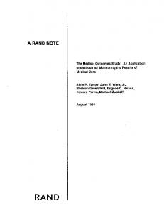
Introduction Ihf Cctitral Ratul tioldficld is siluait'tl in the souih of Johannesburg (Figure 1) and is host to one of the most cxtetisive gold rescrve.s in tlit- work! (Nohh uncl Kohh. I99H), By Llie late l%()s and early I'rOs. most of the minitig in the Central Rand Goldficld had ceased, atitl CLirrc-nily, only one mint- is still operational, namely Hast RantI Proprietary .Mitics (KUPM), [n ihc early 19K()'s. interest was re\ivetl in the Clentral Rand Cloklfiekl Ix'cause of an increase in the gold price, antl mining dowti-dip from ihc old mine \vorking.s was fO[i,sitlerctl. The area ciirreiitK utider consideration has heconie known as the Argonaut. Sotnh WITS or South l-entral Kami area, and is lociiteti as a down-dip extunsioti, to
tlie south, of the defunct Central Rand Goklficld. With mining projcctc-tl to exceed depilis of i2(K)m. the feasibility of this project relie.s hea\ily on thi.' level of confiticnco of predictt'ti ore resources, which, in turn, depetid,s ()n a confiiient geological model oiillitiing the distribiilifjn ant! nature of the orchotly, T!K' Maiti Kee! anJ Main Reef [.eadcr are the pritnary target orebotlies of the South Central Kand. These orebodies form part of the Main Cong!otnerate Formalion of the Jdlianncshtirg Subgroup (iMgures 2 antl 3). ;md are separatetl by the Black Bar. except in the eastern ]ian,s of the Basiti (KKPMI, where they tnergc with the o\erlying Soutli Reef to form v\hat i.s refened to as the (iotnjjositc Keef (Jones, 1936) (Figiirt- 3,)- Jones
SOUTH AFRICAN JOURNAL OF GEOLOGY. 20(1 (.VOLfME lO"" PAGE 60.V6I8
604
TECTONOSEDIMENTARY MODEL FOR rtlE CENTRAL RAND GOLDFIELD
Durban Roodepooct Deep Rand I Leases
18*
Rose Oeeu
• KRBS
Wi (waters rand Gold Mine
* KRB3
^ ^ a ^ - f . ' T - - ' ' E a s t Rand Goldfield 32'
Central Rand Goldfield
i /
'
""^ ^, '^vander Goldfield
Key Goldfields Central Rand Goldfield (SludyArea) t « Cities / Towns
Figure 1. L(K-alit\- map nltlie \Vitw;iii.TM-.i[Kl Basin, shovviiij; IIIL- iouiiion nt liic CLMiirul R:iiul LHHI OUILT gnldiifk],s I inuditied ;itt.sed thaE the Black Bar and Main Reef Leader diminished to ,such an extent that the Composite Keef wa,s made up primarily of the Main and South Reefs. This .study consider.s .sedimentological characteristics of the Main Reef antl Main Keef Leader at f-RFM Hercules Shaft, and the Compo.site Reef at the Far East Vertical (FEV) Shaft of FRPM (Figure 1), This infonnation is u.sed to propose a tectonosedimentaiy model tor the deposition of the Compo,site Reef in the FKV Shaft area, Ttie Coin[-)osile Reef model Is u.sed as a ba,sis. in conjunction \\iili fin' models, not recognising the impact of syndepositional structural features on conglomerate distribution. Wethmar (1957) first identified a regional northwest-southea.st palaeoflow direction with northeast to ,southwest cross-cuning channels associated with both the Main Reef and the Main Reef Leader. Pretorius (1974) recognised a relationship between regional northwest to southeast oriented anticlines in the goldfield and regional palaeoflow directions, as well as east to west cross-cutting channel orientations, and based his dejiositional model on the fan delta model (Pretorius. 196-+), w ith entr>' points from the northwest and northeast. The fan-delta model recognised normal faulting along the Rietfontein Fault (Figure 2) associated with uplift of the hintedand. During the 198O's a 2D seismic study was carried out in the South Central Kand area. From this, Weder (1983) identified a series of
SOUTH AFRICAN |l Black ear Main Reel
|..m
•°"'
Jeppestown Subgroup
Wesi Rand Gfoup
• / • /
Figure 3 Scratigraphic column of ihe tienlral Kand tiroup a,s it occurs in the Centrai Rand Goldfield (modified afler KinKslev. 1998), AJ,so ilkisirated Is the cnale.-scence of ihe Main Conjilomerale l-nrmatinn and the Soulh Keef from Tiurlxm Kondepoort Deep Mine in the west of the goldfield to Easl Rjnd Proprietary Mines in Lhe easi.
SOUTHAFRICAN jOIRNAI. OF GEOLOGY
606
TECTONOSHDIMENTAKY .MODl'L FOR THE CENTRAL RAND GOLDFIELD
syndiml und :intidin:tl Ibki :ixcs. which he proposed controllct! the depositional patici-ns of the Main Reel and Main Reef Leader, Pretorius (1992) nioditied his model and renuned the northeastern cnir>' poini. Stanistreet ei al. (1986) recognised ihai ilie Riellbntein Fauli (Fij^iire 2) was associated with leftlateral wrenching during Main (xinglomeraie tleposition. Camden-Smith and Stear (1986) utilised thi-s information. to propo.se a left-lateral wrenching model that controlled the deposition of the Conipo-sile Reef at ERHM. They further proposed that cross-cutting channels obser\ed by Wethmar (19S7) resulted from successive shoreline migrations. Grohmann (19H6. 198H) compiled and interpreted 1:10 OOO structure plans of the entire c:entral Rand Goldfield from 1:1 ()()() mine stnictiire plans. Through this investigation. Groliniann (19KH) recognized southerly dipping, east to west trending normal faults. related to the uplift of the hinterland that formed during Witwatersrand deposition. He further propcised that letilateral wrenching along the Kietfbntein Fault (Figure 2) resulted in the formation of Riedel s!iears, Riedel conjugate shears, principal shears and P-shears (Wilcox etal.. 1973). and that the.se shears were of Ventersdorp age, based on dyke ages identified by jeffer>' (I97=>). Grohmann (19HH) also recognized thrust and normal faulting associated with left-lateral wrenching. The rising of the Johannesburg Granite Dome resulted in the reactivation of normal faults in a reverse sense (Grohmann. 19HH). Bushveld deformation was a.ssociatetl with east to west compression (Roering. 1986; personal communication in: Grohmann. I9H8), and dyke emplaccmeni into pre-existing fault planes occurred. Grohmann (19KB) recognized that Ventersdorp-age wrenches were reactivated in a right lateral sense during this compression. Since the late l9S0's. there has been litlle work contlucted tin tectono.sedimentaiy moticlling ot the Central Rand Goidfield. However, regional modelling ot the tectonic development of the Witwatersrand Basin by authors such as Myers et ciL (1990). combined with the findings by Charlesworth and McCarthy (1990) on the Rietfontein Fault (Figure 2). have provltled sufficient atiditional information lo rc\ie\\ and retinc pre\-iously proposed motleis. The Main Reef, Main Reef Leader and Composite Reef at ERPM Main Reef and Main Reef Leader at Hercules Shaft The thickness and characteristics of the Main Reef arc highly variable o\er distances of less than SOm. It consists of one to four di.stinguish:tble conglomerate units scparatetl b\' ([ULinzite lenses. The conglomerates art- matri.\-supponed (approximately 3(*'-ii to "^(Wi, matrix material) and are polymictic. consisting t)l white (9()"ii) and smoky (5%) vein quan7; clasts anti chert clasts (S*'/iO that vary from 2 to 4cm in size- Sulphide mineralisation in the conglomerates is variable, but, on average, they are moderately mineralised ( 10 tc) l"^"-! of the matrix) by predominantly disseminated euhedral pyrite (
c «
s CM
c
1
1 1
•A
1
•§
S
1 1
(0
1
55
cn
cn
(0
(Q
• 1
s 3
onformity
:ite: Unit
rtzit:e and Bl
i_
O
cr
;;
ra
5 in
m
a» ra ra-*
ra S en c
1
fm
•
'•'•'*
•
^ ^ H
m
• ^
Kyity^y.:
Is*; H^
M CO
I• P ,;."; Si ::;|i H • 91 .II*-
CO 5
C
o «
tio
COI c _
.'•:-
1
c
vSI K:
1
• '••i .•_!; *
-- . : - : * ?
CO
Units
1
1
>
•
1
en
— 1 ^ ^
c
•a 1
PI
_i
CM
8
1
han
cr
:3
c
.£
c
n
3
D
to
55
face
LBan
TO
a ot a lA
o s
1 £
0) O)
in u)
1
tag
^
—
"5
1 1
tio
w
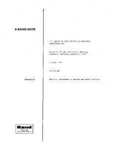
hs on which lhe Composiie Reef w;i.s depo.sited (Figure 5.1). Siage 2 include.s lhe deposition of the Main Reef. Main Reef hangingwall qiumziie and Black Bar (Units 2 to 5). This stage is initiated with the tower Main Reef conglomerate (Unit 2). which is a poorly sorted, large pehl:)le conglomeraie deposited in a fluvial environment. Deposition was restricted to palaeolow or down-warpcd areas (Figure 5.2a). The upper portion of the Main Keef (Unit 3) is a well-sorted conglomerate, intlicaiing a degree of winnowing associated with a lower flow energ)' regime. The presence of trough- and herringlione cross-bed ding in quartzites associated with Unit 3 indicates an interactive fluvial and marine .setting. The remainder of Stage 2 tieposition is associated with a waning How deposit and the continuation of [he marine transgression, during which the Main Keef hangingwall cjuartzite (Unit 4) and the liiack Bar (Unil S) were deposited (Figure S.2h). The deposition t)f the hangingwall quartzite was fairly pervasive except for the palaeohigh areas, where the Black Bar was deposited unconfonnably on the footwal! quartzite palaeohighs. Tectonism continued throughout Stage 2 deposition, and the Main Keef Leader palaecxsurface. thus, resembled the Main Keef palaeosurface, although less accentuated (Figure S.2c) due to deposition in palaeolow areas. Stage 3 is the deposition of the Main Reef Leader conglomerate. The basal tinconformity of the Main Keef Leader (Unit 6) indicates an increase in flow energy and a return to a fluvial environment. The deposition of the Main Reef Leader resulted in erosion of" the Black Bar (Unit 5) and the Main Keef hangingwall quartzite {Unit 4), eroding these units in the down-warped areas (Figure S.3a). The Black liar was onl>' preserved on
609
paiaeohighs that were not subject to extensive erosion (i.e. lower flow energy regimes. Figure 5.3a). Stage 3 culminaled with a marine transgression, associated with the deposition of the Main Reef Leader hangingwall quartzite (Unil 7, Figure 5.3b). Stage 4 signifies the deposition of the South Keef (linii 8), associated with a marine regression and an increase in flow energy. In contrast u> the Main Keef and (he Main Keef Leader deposition, the South Keef was formed by predominantly aggradational deposition, resulting in a discontinuous small pebble conglomerate. Tectonic activily pre\'ailed during the deposition of the South Reef, w ith the majcjrity of the conglomeratic areas being confined to palaeolows (Figure 5.4). Similar to Stages 2 and 3, Stage 4 represents an upward-fining sequence with the South Reef grading into a quartzite. Cenlral Rand Goldfield Sedimentological Modelling An undergrountl grade sampling data base (supplied by Durban Roodepoort Deep Limited) has been used to identify variations in large-scale sedimentary features of the Main Reef and Main Reef Leader. The Main Reef data encompa.sses individual sampling points from both development and stope sampling, and includes channel thickness measurements between Durban Roodepoort Deep (DKD) and City Deep Mines (Figure \). The Main Keef Leader data comprises only development sampling data and has been regularised to 25m x 25m blocks. Main Reef Leader data includes channel thicknesses and percentage conglomerate information from an area between Consolidated Main Keef and Simmer and fack Mine (Figure 1). For sedimentological modelling purposes, three lateral facies are defined, which corresponti to three tiepositional regimes (Figure 6).
West
East
Facies 3
Facies 2
Facies 1 —
! -
Fades 2
Facies 3
I
Key 0 Clast-supported M-LPC Clast-supported S-MPC
ly^ Matrix-supported S-MPC
Quartzite lense
•Ti*'. Pebbly-quartztte
Figure 6 .SLlu>ni;itk- illListr.ition t>t .i "clianni-l ct)iiii;il(.-\' indkLiiiiifi IIK- di.striliiiiion ol UiriLTcnl latic^ detLncd in lliis siudy and rlit- rtK'k ry-jK-s tinii a)inpri.st.- c-adi taciirs (SPG - Small peliblc •.•onglonKTulc, MFC - Medium pcbblt- conglomerate and LFC - L;irye pt^bhle
SOUTH AhKiCAN JOtlRNAL OF GEOLOGY
610
TECTONOSEDIMENTAKY MODHL I-C)K Till- CKNTKAL KAND GOLDFIELI)
Channel Thickness (cm)
Durban Roodepoort Deep
Rand Leases
Facies 2
Facies 3 Kilometres
- Erosion channel 10
Figure7 l.sop;K-|i plan ot Iht- M;iin Rvc\ ;is ik'linL'd in lhe rcxi.
15
20
L-. Indifali-d on lhf isopacli [>l;in AW tin- .M'tiiiiifnioloyjc;!! {.idv^ jnd the channel
Facies 1 rcprcsfnls ihc main channel complex, Facies 2 ihc channel flanks, and Facies 3 the o\erbank area. Main Reef antl Main Heel Leader data were contoured ro produce i.sopach plans, which were iisetl to itientily channel axes (definet] by a line ihai passes ihrougli ihe cenire (^t a localisetl area of iliick conjilomeraie) and classify ihc orel"KK.iies into regional sedinieniological lacies (Facies 1 to 3: Figure (i). Main Reef Sedinientolog>' From lhe i.sopach plans (Figure '). Facies I to 3 (Figure (l) were classified according to the following .scheme:
Facies 1: Average channel ihickness > I^Ocni Facies 2: Average channel Uiicknes.s heiwcen \{H) anti ISOcni Facies ,^: Average channel thickness < lOOcrn The largest channel complex (Facies 1) of the Main Reel' is siluateti in the I)KI> Mine area (Figure ~). where channel wiiiths of up lo 9ni ociiir (W. Siear. \enmyn KantI, persttnal conimLinication. 2003). The Main Reef rapidly ihins to ihe easi of" DHI> antl ihen ihickens grai-lualiy in the Kantl Lease.s and Consolidaled Main Reef (CMR) mine areas (Figure ~). The remainder ol lhe goldfield consists of Facies 2 and 3 areas, wiih slightly ihicker Main Reef de\ eloped in ihe Robinson Deep and City Deep area. The dominant channel orientation is northwest to southeast, conforming to palaeollow ilirections measureil by se\eral auihors U'.,t;. Reinecke. 1927: '^elhmar. l')S7; Slear 198(1), In addition to the regional north west./southeast palaeoflow direction, less prttminent eross-cuiting channels also ocx'ur. panicLilarly in lhe eastern pans of the study area, oriented apprt)ximalely norlh-northeast/south-southwest and
east/west. These cross cutting channels were also ob.scrved by VC'eihmar (lyS''). wln) noletl mirlheast' southwest trending channels, ami by Pretorius (1974), who noted east/west orientei.1 clianiiL-ls. Erosion channels (Figure ~) oriented northea.st/ .soLiihwcsi erotie ihe Main Reef. One such channel was observed in a surface exploration borehole (KRB •\) lo the soLith of Cii\ Deep Mine (I'igvire I). The channel is siraiigniphitally siiualed beneath lhe .Main Reef header and filled with hlack Bar niaierial. It is approximately 23m dee[i antl consists of a Tm ihit k basal conglomerate overlain by a homogencou.s, siliceous quartziie that grades upwards inio a fine-grained, argillaceous ([iiart/ite. l"he basal conglomerate is clasr-siipponed, jiolyniictic antl devoid of any macroscopic sulphide inineralisaiion. Main Keef Leader Sedimentology Similar to the Main Reef, isopach [ilans for the .M:MII Reef Leader have been used to cla,ssif)' facies anti lo itientify channel axes. The Main Reef Leader is characieri,sed by thinner channel tliicknesses relative to the Main Reef, and lhe facies classification i>. thus, ba.setl t>n reduced Ihickness inier\als: Facies 1: A\erage channel thickness > 60cm Facies 2: Average channel thickness between 30 to 60cm Facies 3: A\erage channel thickness < 30cm The isopach plan for the Main Reef Loader (Figure H) illustrates that a channel complex (Facies 1) is situated in the Robinson Deep Mine area. Similar to the Main Reef, the regional palaeoflow directicjn is in a northwest/ southeast oriental ion wiih cross-cutting channels oriented in norlhea.st/Souihwesi and easi wesi directions. A ctmiparison between the channel axes and
SOUTH AFRICAN rot'RNAl. OF (.F()l.l IIK- Main KLVI L^'aik-r
15
20
nj; inn^rnul t|ii;irizin-). Als
on the
plan aa- IIK- .sL'tiiinenLulo^ita) latiL'.s and ihf iliannt-l axes, a^ dc'lined in Ki^iia- S.
the total con^lomt-Tatf thickness (i.e. excluding internal quartzite) confirms the position of the channel axes (Figure 9). Structural Modelling Pre- and syn-depusitional structures are considered. Syndeposititmal fold axes were identified hy Weder (1994) based on lhe Main Bird Isopach (base of the Main Bird series defined from the lop of the jeppesiown SuhgroLip to the lop of lhe Uooysens Shale Formation. Figure 3) determined by a 2D seismic investigation (Weder. 1983).
The isopach plan (Figure JO) was also con.sidered hy Reading and Reynolds (1993), who noted that the upper portion of the Booysens Shale represents a transitional contact over 100m - therefore not representing a high density reflector. In atkiition. the isopach interpretation does not consider intrusives and structural gains (duplication) and losses that are obserwd in surface exploratitjn boreholes. Based on the logging of boreholes, Reading and Reynolds (1993) estimated new isopach thicknesses (Table 1) that exckided intrusives and considered stmctura! gains and losses (Figure 10).
SOUTH AFRICAN JOURNAL OF (IROLOGY
TECTONOSEDIMENTARY MODEL 1 OR THE CENTRAL RAND GOLDEIELD
612
Figure 10 Syn-ck-pusitiunjl fold a x c i idt-niitifd by WttkT (I'W t). C(il(Kiri.\i Ullctl .sqiun-.s intliuik- llic Bird S(_•IiL•^ lliiLkni-.s.si.:^ ;i.s iiiciLsiircd along seismif lines a n d used hy WetkT ( ! W i ) tu a i n t o u r the Bird Scries i.sopuch. Unfilled coloured squares rt-preseni the Bird Series [hickness as m e a s u r e d rroin horelu)!e core by Ke:iding antl Reynolds (
Durtan Rand ConsolkJated Roodspooft Deep Leases Main Reef
Crown Minos
Robinson Deep
Cfty Deep
Simmer and Jack
ERPM
South Raat Main Roef Leader Main R«ef North Roel
(2D S»WI!K: Survey! urn 1 a
11
Bird ThidcriM*
HegiDfi-il .iiul louil
a.s deleiniiiieii Ll^ing tonuniretl iiird Series ihickness tluia and a cro.s.s-setlildficltl by depositing Black Bar material (now silt, shales anti fine grained quartzites) into topographically lower lying areas (Figure 17). The palaeotopography prit)r tt) Main Reef Leader deposition was. thus. smootlied relative to Main Reef palaeotopography and consisted of a single down-warped area centred in the c:ity Deep Syncline that was boundeti by the DRD Anticline and Springs Monocline (Figure 17). The Main Reef Leader was deposited in an elongated channel complex (Figures 8. 9 and 17). similar to the deposition t>f the Main Reef. The positit>n of the channel complex indicates a sliift in the depositional axis from the DKD Syncline during Main Reef tlepositit)n to the City Deep Syncline during Main Reef Leader deptisition. The Main Reef Leatler is typically a thinner reef package antl associatetl with less internal quartzite. relative to the Main Reel, indicating a higher level of degradational
SOUTH AFRICAN JOtlRNAL OF C.EOLOGY
R.A. STEWART, W.ll RFIMOLl) AND K.C. CHARLESWORTH
\
\
617
\
17 S(.lio'iiialic crass-section indiCLilin>; the palacoinjTojjriipluc \;irialiim.s prior ro Miiin Reef dcpi)silion throiigli ihc M:iin Kivt Lc palat'otopography. The isopach plans ol' ihi.' Main Ri.vt', Main Ht-i-f Main Ki'd' t.eLuifr [timing (at'liT Wethmar, iy^7) antl Main Lfadcr illu^l^ate tiuit thkkesi n-cf packajjes (Kxur in [opo}4rHphuail\ lou areas, illtisiraiinj^ the liming ot lliese toki sinitture.s.
activity. po.ssibly associated with more intensive antl prolonged flooding pcriod.s. Diirinji Main Reef Leader deposit ion, brittle deformation as.sociated with leftlateral wrenching continued and influenced Main Reef Leader channel orientations resulting in northeast/ southwe.st and easi west cross-cutting channels. Conclusions This investigation ot" the Central Rantl Goldfield has illuslrated that .sedinientation and structural features are not mutually exelu.sive and that structural control.s influenced the observed .sedimentation patterns. A tectonosedimentary model is proposed for the Composite Reef at Far Fasi Vertical Shaft, FRPM. Contrary to Jones' (1936) proposal and Hiller and Mason's (1982) interpretation, our model suggests thai the Composite Reef at Far Fast Vertical Shaft consi.sts of the Main Reef and Main Reef Leader, and the South Reef
sporatlically occurs in ilie hangingwall. The model recognizes underlying lettonic controls that persisted throughout the dep.,!. anil Reynolds. A..r. IW3. The Somh VCimalt-rsnind I'rojfit. I'lipiihluhi'il ItiU-riiat Ri'fHin. RIDHI Mines. 1-2.1. ik-MK'ckf. I.. (I')2"l. '\'\\v loi-.i!ioii of payalik- uri'l«>d]es in IIR- gok!-lifarinj> rL'fls i>l iht,- V.irwait-r.-.r.tnd TrciiiHictuiHs iifllv (k-nloiiiciil Si}»K1, tiuld in llu.- VL imakTsrand li:isin. In: .MG.C. Wilson und C.R. .\nli;n.'us.>isil,i. 32. 3.1 .sivniirius relt'vam m tlu' devdopnicni (if ihe Lite .\rdioan WawaR-rsraiid lVj>,\n.Ji)iiriiul if .Afriain Huitb .Sck'iici: 13. dS-Hl. SlL-ar. W.M. iTMil. .^ Crilit-al ovaliiaiion of iht- Main Kivf Leader in ihf Siiulh Witwaiersrand t)ffp l.fvel I'ruii-it Art^i. I iijiuhlishcilI'lhriiul Rcforl Kiivtl MUiLv. 1986/2. l-^y. Wc-der. E.I!.W. (I9K3). The .NigniliiMme ol gnivil\ .mil >fisinii rfllfelion lechniques in deriving a new siimHirjl nwiilet for llit- arta south i)l' the Cenir.il Hand c '.iiidfit-kl. / iipiihlishi'it htlcriuil Rcpurt, Ruiiii .Miiifs. Au/Win/35. lOI-l n. Wt-dei. l-.l-'.W f IWi) SlnnUire ot I he .irt-.i soulh ol ilie C.t-iiln:l R.ind gold mines as derived lri)in .i gr.iviiy and vihroseis surveys. XVIh C.MMI ii};rfs.s. Soiilh Africuii !ns!lliitfif.Minliifitti!ilMvti.ilturny. 27I-2HI. Weihmar. H, ( W^~). Deep U-vel Mining inve.siigatUm inm iht- possihilitie.s ol rinding pay urv ai ck-pili tin llit- tX-ntral Riind From D.R.D. Ui K.R.P.M, / 'iipuhlishftl Iiili-rnal Coiisullimcy Ri-fxni. Rniicl Mimv. I -11. Wikdx. R.I-:., Harding. *l.i'. ami SeeU. D.K. ( I ' r 3 ) . Hasii- wrenth twtonk's. Uiilk'liii if the Amcriian Asyiititinu if I'vfnilvinn (li:fik