SANDIA REPORT SAND2010-6013 Unlimited Release Printed September 2010
Temperature-Dependent Mechanical Property Testing of Nitrate Thermal Storage Salts Scott T. Broome, Brian D. Iverson, Nathan P. Siegel, Randy L. Everett, and David R. Bronowski
Prepared by Sandia National Laboratories Albuquerque, New Mexico 87185 and Livermore, California 94550 Sandia National Laboratories is a multi-program laboratory managed and operated by Sandia Corporation, a wholly owned subsidiary of Lockheed Martin Corporation, for the U.S. Department of Energy’s National Nuclear Security Administration under contract DE-AC04-94AL85000 Approved for public release; further dissemination unlimited.
Issued by Sandia National Laboratories, operated for the United States Department of Energy by Sandia Corporation. NOTICE: This report was prepared as an account of work sponsored by an agency of the United States Government. Neither the United States Government, nor any agency thereof, nor any of their employees, nor any of their contractors, subcontractors, or their employees, make any warranty, express or implied, or assume any legal liability or responsibility for the accuracy, completeness, or usefulness of any information, apparatus, product, or process disclosed, or represent that its use would not infringe privately owned rights. Reference herein to any specific commercial product, process, or service by trade name, trademark, manufacturer, or otherwise, does not necessarily constitute or imply its endorsement, recommendation, or favoring by the United States Government, any agency thereof, or any of their contractors or subcontractors. The views and opinions expressed herein do not necessarily state or reflect those of the United States Government, any agency thereof, or any of their contractors. Printed in the United States of America. This report has been reproduced directly from the best available copy. Available to DOE and DOE contractors from U.S. Department of Energy Office of Scientific and Technical Information P.O. Box 62 Oak Ridge, TN 37831 Telephone: Facsimile: E-Mail: Online ordering:
(865) 576-8401 (865) 576-5728
[email protected] http://www.osti.gov/bridge
Available to the public from U.S. Department of Commerce National Technical Information Service 5285 Port Royal Rd. Springfield, VA 22161 Telephone: Facsimile: E-Mail: Online order:
2
(800) 553-6847 (703) 605-6900
[email protected] http://www.ntis.gov/help/ordermethods.asp?loc=7-4-0#online
SAND 2010-6013 Unlimited Release Printed September 2010
Temperature-Dependent Mechanical Property Testing of Nitrate Thermal Storage Salts Scott T. Broome, Randy L. Everett, and David R. Bronowski Geomechanics Department Brian D. Iverson and Nathan P. Siegel Concentrating Solar Technologies Sandia National Laboratories P.O. Box 5800 Albuquerque, NM 87185-0751
Abstract Three salt compositions for potential use in trough-based solar collectors were tested to determine their mechanical properties as a function of temperature. The mechanical properties determined were unconfined compressive strength, Young’s modulus, Poisson’s ratio, and indirect tensile strength. Seventeen uniaxial compression and indirect tension tests were completed. It was found that as test temperature increases, unconfined compressive strength and Young’s modulus decreased for all salt types. Empirical relationships were developed quantifying the aforementioned behaviors. Poisson’s ratio tends to increase with increasing temperature except for one salt type where there is no obvious trend. The variability in measured indirect tensile strength is large, but not atypical for this index test. The average tensile strength for all salt types tested is substantially higher than the upper range of tensile strengths for naturally occurring rock salts. 3
Acknowledgments The authors would like to thank Tom Pfeifle and Darrell Munson for their critical review of this report.
4 4
Table of Contents Abstract ......................................................................................................................................................................... 3 Acknowledgments ......................................................................................................................................................... 4 Introduction ................................................................................................................................................................... 7 Salt Cores and Specimen Preparation ............................................................................................................................ 7 Sample Nomenclature................................................................................................................................................ 9 Mechanical Property Test Methods ............................................................................................................................... 9 Tensile Strength ......................................................................................................................................................... 9 Unconfined Compressive Strength .......................................................................................................................... 11 Calibration ............................................................................................................................................................... 12 Experimental Results ................................................................................................................................................... 12 Indirect tension tests................................................................................................................................................. 12 Unconfined compression strength tests ................................................................................................................... 15 Coefficient of Thermal Expansion ........................................................................................................................... 22 Summary...................................................................................................................................................................... 22 References ................................................................................................................................................................... 23 Appendix A – Unconfined Compressive Strength Tests ............................................................................................. 24 Distribution:................................................................................................................................................................. 34
Table of Figures Figure 1 Salt pouring method and illustration of void formation at top of specimen. ....................................... 8 Figure 2 Example of salt core cut to length using a wire saw. ............................................................................ 9 Figure 3 Post-test images of samples SS-BZ63-B03 and SS-BZ21-B01. Note vertical diametric crack; this is the crack along which these samples broke when deformed. ................................................................ 10 Figure 4 UCS test setup showing sample mounted inside an environmental chamber and instrumented with axial and lateral displacement transducers................................................................................................... 11 Figure 5 Computer-controlled servohydraulic load frames used to conduct UCS and indirect tension tests: a) 22,000 lbs. capacity and b) 220,000 lbs. capacity. .............................................................................. 12 Figure 6 Example of load distributed over an area for an elevated temperature indirect tension test. ....... 14 Figure 7 Indirect Tensile Strength versus homologous temperature for salts A, B, and C........................... 16 Figure 8 Peak Stress versus homologous temperature for UCS tests. ........................................................... 17 Figure 9 Peak Stress versus homologous temperature and density for UCS tests. Normalized sample density is represented graphically by the size of the data symbol. ................................................................... 18 Figure 10 True Stress versus True Strain plot for sample SS-UC21-A08. ..................................................... 19 Figure 11 True Stress versus True Strain plot for sample SS-UC21-A08 showing regions used in determining Young’s modulus and Poisson’s ratio. ............................................................................................. 19 Figure 12 Initial Young’s modulus and Poisson’s ratio versus homologous temperature. ........................... 20 Figure 13 Young’s modulus and Poisson’s ratio versus homologous temperature. Data points are values determined from initial loading as well as from unload/reload cycles. .............................................................. 22
Table of Tables Table 1 Table 2 Table 3 Table 4
Proposed test matrix. .................................................................................................................................. 7 Indirect tension test results for each salts A, B, and C. ....................................................................... 13 UCS test results: density and peak stress. ............................................................................................ 17 UCS test results: Young’s modulus and Poisson’s ratio. .................................................................... 21
5 5
6 6
Introduction Interest in raising the operating temperature of concentrating solar technologies and the incorporation of thermal storage has motivated studies on the implementation of molten salt as the system working fluid. Recently, salt has been considered for use in trough-based solar collectors and has been shown to offer a reduction in levelized cost of energy as well as increasing availability (Kearney et al., 2003). Concerns regarding the use of molten salt are often related to issues with salt solidification and recovery from freeze events. Differences among salts used for convective heat transfer and storage are typically designated by a comparison of thermal properties. However, the potential for a freeze event necessitates an understanding of salt mechanical properties in order to characterize and mitigate possible detrimental effects. This includes stress imparted by the expanding salt. Samples of solar salt, HITEC salt (Coastal Chemical Co.), and a low melting point quaternary salt were cast for characterization tests to determine unconfined compressive strength, indirect tensile strength, coefficient of thermal expansion (CTE), Young’s modulus, and Poisson’s ratio. Experiments were conducted at multiple temperatures below the melting point to determine temperature dependence.
Salt Cores and Specimen Preparation In an effort to span the typical range of melting point possibilities of thermal storage salts, three representative salts were selected for mechanical properties testing: solar salt (60 wt% NaNO3, 40 wt% KNO3) (Pacheco et al., 1994 and Bradshaw et al., 1987), HITEC salt (Coastal Chemical Company, 2010), and a low melting point quaternary salt (42.3 wt% KNO3, 39.4 wt% CaNO3, 12.1 wt% NaNO3, 6.1 wt% LiNO3) (Bradshaw et al., 2009). In this report, these salts are referred to as salts A, B, and C in the order described above. Table 1 lists the melting temperature (Tm) for each salt type and shows the proposed testing matrix. Table 1 Proposed test matrix.
Salt Type & Melting Temperatures A Tm= 221oC Tm= 494K B Tm= 142oC Tm= 415K C Tm= 90oC Tm= 363K 1
Unconfined Compression 21oC = 0.60Tm, 127oC = 0.81Tm, 152oC = 0.86Tm, (2 tests at each condition) o 21 C = 0.71Tm, 63oC = 0.81Tm, 84 oC = 0.86Tm (1 test at each condition)
Indirect tension Young’s Poisson’s (Brazilian) modulus1 ratio1 Test temperatures 21oC = 0.60Tm, 127oC = 0.81Tm, All 21oC 152oC = 0.86Tm temperatures (2 tests / temp) 21oC = 0.71Tm, 63 oC = 0.81Tm, All 84 oC = 0.86Tm temperatures (2 tests / temp)
21oC
21oC = 0.81Tm, 21oC = 0.81Tm, All 39oC = 0.86Tm, 39oC = 0.86Tm, (1 test at each temperatures (2 tests / temp) condition)
21oC
CTE 1 Test 10oC measurement increments. 21°C to 0.95 Tm 1 Test 10oC measurement increments. 21°C to 0.95 Tm 1 Test 10oC measurement increments. 21°C to 0.95 Tm
Determined from unload/reload cycle data
7 7
Cylindrical salt samples were cast in a PTFE tube with silicone stoppers and then extracted for mechanical property testing (see Figure 1a). Molten salt was poured so as to fill the PTFE tube contiguously and avoid layer formation in the salt. The samples were cooled at room temperature. Figure 1b shows cratering near the top of a sample (due to phase-dependent density change) and void formation in the salt-core interior that occurred in some cast samples. These areas were avoided by cross-sectioning and selecting unaffected regions of the solidified salt.
a
b
Figure 1 Salt pouring method and illustration of void formation at top of specimen.
Samples received by the Geomechanics laboratory were cut to length using a wire saw as shown in Figure 2. Unconfined compressive strength (UCS) samples were cut from near the bottom of each casting while maintaining an approximate 2:1 length-to-diameter ratio (L:D). Next, the specimens were mounted in a surface grinder where the ends of the specimens were carefully ground flat and parallel to within a tolerance of 0.001 inches. Preparation of the UCS samples followed the general outline given by ASTM Standard D-4543 (ASTM, 1995). One sample of each salt type was turned down to a smaller diameter using a lathe. This operation was done to ensure the UCS could be obtained within the capacity of the loading frame used for elevated temperature testing. As-received sample diameters were used for all other UCS testing. Specimens used for tensile strength determinations were sawn from cast cylinders to produce L:D ratios of 0.5; the ends of the specimen were not ground. For indirect tension specimens (also referred to as Brazilian disc tension tests), the sides were left undressed to avoid damage that could occur in standard machining operations. Indirect tension specimens were prepared following the general outline given by ASTM Standard D 3967-08 (ASTM, 2008). At the completion of the specimen preparation step, the density of each test specimen was calculated from the measured mass divided by the sample volume calculated from the specimen dimensions, assuming each specimen was a perfect cylinder.
8 8
Figure 2 Example of salt core being cut to length using a wire saw.
Sample Nomenclature Project -
Type of Test
Testing Temp – Sample Composition
Sample Number
Solar Salt - UC – Unconfined Temperature - “A” Solar Salt Number BZ – Brazil “B” HiTec Salt “C” Quaternary Example: SS-UC21-B01
Mechanical Property Test Methods Tensile Strength Tensile strength was determined using ASTM D3967-08, Standard Test Method for Splitting Tensile Strength of Intact Rock Core Specimens (ASTM, 2008). However, this method could not be followed explicitly after an initial trial test concluded the loading rate needed to be increased above the recommended guidelines. The higher loading rate was necessary to counter sample creep at elevated temperatures to insure sample failure before large creep deformations could occur. The splitting tensile strength test (or Brazilian test) is an indirect method for determining tensile strength because compressive stresses are applied in one direction, which in turn, induce tensile stresses in an orthogonal direction. Tensile strength can also be determined using a direct-pull, 9 9
uniaxial test configuration, but such a method is more difficult to perform and more expensive when compared to the indirect method. Therefore, tensile strengths measured in this study made use of the indirect method and thus will be referred to as indirect tensile strengths. In the splitting tensile strength test, typically a rock disk, having a length/diameter (L:D) = 0.5, is diametrically loaded between rigid platens (with bearing strips) until failure occurs. Because of the arced shape of the disks, the loading is assumed to be along a line rather than distributed over some area. When the compressive line loading induces tensile stresses that reach the tensile strength of the material, the material fails and manifestation of this failure is typically a vertical fracture parallel to the compressive line load (See Figure 3 for post-test examples of failed samples).
Figure 3 Post-test images of samples SS-BZ63-B03 and SS-BZ21-B01. Note vertical diametric crack; this is the crack along which these samples broke when deformed.
The splitting tensile strength is calculated as follows: σt = 2P/πLD where: σt = Splitting tensile strength (psi) P = Maximum applied load (lbs) L = Thickness of the specimen (in.) D = Diameter of the specimen (in.)
1010
Unconfined Compressive Strength UCS tests were conducted by applying compressive loads to the ends of right-circular cylindrical salt specimens (L:D ≈ 2) in axial strain control until failure occurred as denoted by a drop in the axial load. The UCS is then calculated as the peak or maximum compressive force applied to the sample ends divided by the sample cross-sectional area. Electronic transducers were mounted on the test samples to measure axial and lateral sample deformations (Figure 4 illustrates a typical instrumented UCS sample depicting the locations of the axial and lateral linear variable differential transformer (LVDT) displacement transducers). Data acquired from the LVDTs together with axial stress were used to determine elastic properties such as Young’s modulus and Poisson’s ratio. During elevated temperature testing, samples were placed inside an environmental chamber (also shown in Figure 4) that controlled the temperature to within ± 1oC.
LVDT’s for axial deformations
LVDT’s for lateral deformations
Figure 4 UCS test setup showing sample mounted inside an environmental chamber and instrumented with axial and lateral displacement transducers.
Figure 5a shows the computer-controlled servohydraulic testing system used to conduct most of the UCS testing. For some room-temperature tests, the axial load required to fail the samples exceeded the 22,000 lbs. capacity of this two-column reaction frame. As a result, subsequent room-temperature tests were conducted on a larger capacity (220,000 lbs.) four-column load
1111
frame (shown in Figure 5b). Each load frame is equipped with a load cell placed in line with the sample to measure the axial force applied to the sample ends. The first UCS test was conducted at an axial strain rate of approximately 1E-04/sec. However, sample creep was observed during the unload/reload loops performed for elastic property determination so all subsequent tests were performed using an axial strain rate of approximately 1E-03/sec to mitigate most of the sample creep and ensure accurate determination of material properties.
Calibration Data collected in the experimental study included force, temperature, and axial and radial displacements. Typically, these data are acquired using electronic transducers in which the electrical output is proportional to the change in the measured variable. In all cases, the constants of proportionality were determined through careful calibration using standards traceable to the National Institute for Standards and Technology.
Load frame Load cell
Environmental chamber
a
b
Figure 5 Computer-controlled servohydraulic load frames used to conduct UCS and indirect tension tests: a) 22,000 lbs. capacity and b) 220,000 lbs. capacity.
Experimental Results Indirect tension tests Table 2 summarizes the results for all indirect tension tests. Seventeen tests were completed successfully: Seven for salt A, six for salt B, and four for salt C. Early in the testing series, samples were placed between cardboard loading strips, which tended to distribute the load over a larger portion of the sample. Because of the high deformation observed in the material, the cardboard loading strips were removed to help concentrate the sample failure. Subsequent samples were taped around the circumference with two layers of masking tape. The masking tape served two purposes in that it acted as a very thin loading strip and also kept the sample intact after failure. Sample SS-BZ127-A05 did not fail as noted in the Table 2 so the tensile strength was determined from the load that was observed coincident with the greatest deformation.
1212
Table 2 Indirect tension test results for each salt: A, B, and C.
Sample
Homologous Indirect ***Corrected Melting Flattened Test Temperature, Tensile Tensile Density Temperature, Salt Length Temperature TH Strength Strength Tm Type (g/cc) (°C) (K) (%) (psi) (in.) (psi)
*SS-BZ21-A01 *SS-BZ21-A02 SS-BZ21-A04 SS-BZ21-A08 SS-BZ63-A03 SS-BZ78-A06 SS-BZ78-A07 **SS-BZ127-A05
A A A A A A A A
2.16 2.17
2.17 2.15
27 27 27 27 63 78 78 127
494 494 494 494 494 494 494 494
61% 61% 61% 61% 68% 71% 71% 81%
N/A 960 489 559 803 383 606 443
0 0 0 0 0 0.287 0.193 0.468
N/A 960 489 559 803 373 599 412
SS-BZ21-B01 SS-BZ21-B02 SS-BZ63-B03 SS-BZ63-B05 SS-BZ84-B04 SS-BZ84-B06
B B B B B B
2.11 2.11 2.09 2.11 2.08 2.11
27 27 63 63 84 84
415 415 415 415 415 415
72% 72% 81% 81% 86% 86%
453 547 470 458 705 549
0 0 0.165 0.151 0.3 0.27
453 547 464 454 679 534
2.13
*SS-BZ21-C01 C 2.15 27 363 83% 521 0 SS-BZ21-C03 C 27 363 83% 442 0 SS-BZ39-C02 C 2.18 40 363 86% 833 0 SS-BZ39-C04 C 2.19 39 363 86% 427 0 N/A = Load control of sample lost during test *Cardboard loading strips **Sample did not break ***From Jaeger and Cook, Fundamentals of Rock Mechanics, Third Edition Fig. 6.11.1c.
521 442 833 427
Test temperatures for salt A were adjusted downward from the temperatures given in the proposed test matrix (Table 1). Large deformations were observed while testing specimen SSBZ127-A05 (salt A) at 127°C so it was decided to test two samples at 78°C, i.e., a homologous temperature1, TH, equivalent to 71%. This temperature was selected because it allowed for a direct comparison of results between salts A and B at an equivalent homologous temperature (i.e., 71%). In addition, one test at 63°C (TH = 68%) was completed on salt A to provide data at an intermediate temperature. Many indirect tension test samples, especially those tested at elevated temperature, exhibited large deformation before failure. As a result, the arced surfaces of the test samples in contact with the loading platens flattened sufficiently such that the applied line load transitioned to a load distributed over the flattened area. Figure 6 shows an example where the load is distributed over a flattened area before failure. Distributed loads with an arc of 15° or less give similar tensile strength values as those derived from line loads and fail with similar diametral fractures 1
Homologous temperature is defined as the temperature of a material normalized by its melting temperature expressed using the Kelvin temperature scale (K).
1313
provided the load is corrected to account for the contrast between line loading and distributed loading (Jaeger and Cook, 1979).
p
α R
Figure 6 Example of load distributed over an area for an elevated temperature indirect tension test.
Table 2 lists two columns for tensile strength, one in which the line load assumption is valid (i.e., no observed flattening of the samples) and one in which the line load assumption is invalid (significant flattening is observed). This latter tensile strength is defined in Table 2 as the “Corrected tensile strength”. The flattened lengths (e.g., the distance between the blue lines shown in Figure 6) for those tests in which the line load assumption is invalid were measured post-test and are also given in Table 2. The corrected failure load comes from Jaeger and Cook, 1979 and is given by: W = 2pαR, where: W = Corrected load at failure (lbs.) p = Pressure per unit length over contact area α = ½ of the arc over contact area in radians (see Figure 6) R = Radius of specimen (in.)
1414
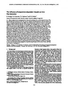
Once the corrected failure load is determined, the corrected indirect tensile strength is calculated from: σt,c = 2W/πLD where: σt,c = Corrected indirect tensile strength (psi) W = Corrected load at failure (lbs.) L = Thickness of the specimen (in.) D = Diameter of the specimen (in.) Figure 7 plots indirect tensile strength versus homologous temperature for salt types A, B, and C. The variability in tensile strength at all temperatures for each salt type is large but not atypical of this type of index test measurement. For a given test temperature, the weakest sample is approximately 50% of the strength of the strongest sample for the same salt type; a trend also seen in natural domal salts. All salt types (A, B, and C) are much stronger than naturally occurring domal salts; a typical upper range of indirect tensile strength for domal salts is 300 psi. The average indirect tensile strength for salts A, B, and C is 599, 522, and 556 psi, respectively. Given the relatively small data set and the range of strengths at a given temperature, there does not appear to be a correlation between indirect tensile strength and test temperature.
Unconfined compression strength tests The UCS of salts A, B, and C were determined by standard compression tests of right circular cylinders as described previously. Seventeen tests were completed: Eight for salt A, five for salt B, and four for salt C. Table 3 lists the peak stress observed in each test along with the density for all samples. Although peak stress is generally synonymous with UCS, there were a few tests in which UCS could not be obtained because loading needed to be stopped before a stress drop (failure) was observed given the large sample deformations that occurred. In these cases, the peak stress was reported although this stress may be somewhat lower than the actual UCS. Typically, mechanical properties such as UCS and Young’s modulus are correlated with physical properties such as density. However, in this study temperature is varied and is the dominant factor affecting changes in both UCS and elastic properties and given the limited number of tests performed, the focus of the subsequent analysis is on temperature effects. Figure 8 plots peak stress versus homologous temperature for all UCS samples. Linear fits using least squares linear regression are given for each salt type comparing UCS (or peak stress) to homologous temperature. Salt types A and C have similar best fit lines in terms of slope and salt type B has a slope of about half of the two other salts. For all salt types, UCS decreases as test (or homologous) temperature increases. There is some scatter in the data, but the scatter is typical for this type of index test on this type of material.
1515
1200
Indirect Tensile Strength (psi)
A
B
C
1000
800
600
400
200
0 0.50
0.55
0.60
0.65
0.70
0.75
0.80
0.85
0.90
TH Figure 7 Indirect tensile strength versus homologous temperature for salts A, B, and C.
Although an effort was made to avoid sections of salt with high void content (recall Figure 1b), some of the scatter in strength could be attributed to small voids in individual samples. Variations in void concentration will impact sample density. Figure 9 plots peak stress versus homologous temperature for all UCS samples along with the normalized density for all samples. The density for a given salt type is shown graphically by the size of each data symbol. The largest and smallest symbols equate to sample densities of 2.22 g/cc and 2.09 g/cc respectively. The salt type with highest density is salt C, while salt A has an intermediate density, and salt B has the lowest density. One data point marked in the legend as “Unknown” is plotted only for reference since the density was not determined for this sample (SS-UC21-C01). There does not appear to be an obvious trend between density and UCS. If a correlation does exist for density and other mechanical properties, it is likely overshadowed by temperature variations and the relative small range of densities observed for the test specimens.
1616
Table 3 UCS test results: density and peak stress. Sample *SS-UC21-A05 *SS-UC21-A06 SS-UC21-A07 SS-UC21-A08 SS-UC78-A02 SS-UC78-A04 SS-UC127-A01 SS-UC127-A03
Salt Type A A A A A A A A
Length (in) 3.647 3.777 3.816 3.527 3.595 3.477 3.498 3.616
Diameter (in) 1.715 1.716 1.720 1.711 1.723 1.563 1.719 1.714
Weight (g) 299.8 310.3 314.8 289.5 294.7 235.0 288.6 297.6
Density (g/cc) 2.17 2.17 2.17 2.18 2.15 2.15 2.17 2.18
Peak Stress (psi) 18800 23664 26153 26941 9232 6124 4921 1201
SS-UC21-B02 SS-UC63-B03 SS-UC63-B04 SS-UC63-B05 SS-UC84-B06
B B B B B
4.148 4.095 3.527 3.520 3.638
1.949 1.960 1.720 1.591 1.716
423.7 427.8 284.3 242.4 294.2
2.09 2.11 2.12 2.11 2.13
11591 6886 7955 6683 4622
SS-UC21-C01 C 4.162 1.970 N/A N/A 7413 *SS-UC21-C04 C 3.523 1.656 276.6 2.22 4246 SS-UC39-C02 C 4.103 1.973 449.7 2.19 536 SS-UC39-C03 C 4.070 1.983 448.7 2.18 969 N/A = Weight and therefore density not determined pre-test * For these samples peak stress is defined in terms of engineering stress. All other stress values are defined in terms of true stress.
30000 A Linear (A)
B Linear (B)
C Linear (C)
Peak Stress (psi)
25000
20000
15000 y = -102197.99x + 83913.12 2 R = 0.88
10000 y = -45339.57x + 43813.60 2 R = 0.96
5000 y = -102386.17x + 88796.14 2 R = 0.83
0 0.50
0.55
0.60
0.65
0.70
0.75
0.80
0.85
0.90
TH Figure 8 Peak Stress versus homologous temperature for UCS tests. 1717
30000
Peak Stress (psi)
25000
Normalized density where 1.00 = 2.22 g/cc and 0.00 = 2.09 g/cc.
20000
15000
10000
5000
0 0.50
0.61 0.58 0.57 0.66 0.41 0.45 0.59 0.65 0.00 0.17 0.20 0.18 0.33 Unknown 1.00 0.73 0.66 0.55
= Salt A = Salt B = Salt C
0.60
0.65
0.70
0.75
0.80
0.85
0.90
TH Figure 9 Peak Stress versus homologous temperature and density for UCS tests. Normalized sample density is represented graphically by the size of the data symbol.
Young’s modulus (YM or E) and Poisson’s ratio (PR or ν) were determined from true axial stress versus true strain plots using least squares linear regression. Young’s modulus, E, is defined as: E = Δσa / Δεa where Δσa is the change in true axial stress and Δεa is the corresponding change in true axial strain. Poisson’s ratio, ν, is defined as: ν = E / (Δσa / Δεl) where Δεl is the change in true lateral strain corresponding to the change in true axial stress. An example stress versus strain plot is shown in Figure 10 and plots for all UCS samples are given in Appendix A. Figure 11 shows a zoomed in region of Figure 10 and illustrates the linear regions used in calculating YM and PR. YM and PR were calculated from the most linear portion of the unload curve in the unload/reload cycles.
1818
30000
True Stress (psi)
25000
20000
Axial Lateral Volume
15000
10000
5000
0 -0.01
-0.005
0
0.005
0.01
0.015
0.02
True Strain Figure 10 True stress versus true strain plot for sample SS-UC21-A08.
10000 Axial Lateral Initial YM Initial PR 1st Unload YM 1st Unload PR 2nd Unload YM 2nd Unload PR
9000
True Stress (psi)
8000 7000 6000 5000
Initial YM = 2.66 E+06 1st Unload YM = 3.12 E+06 2nd Unload YM = 3.29 E+06
4000 3000
Initial PR = 0.25 1st Unload PR = 0.31 2nd Unload PR = 0.30
2000 1000 0 -0.002
-0.001
0
0.001
0.002
0.003
0.004
0.005
True Strain Figure 11 True stress versus true strain plot for sample SS-UC21-A08 showing regions used in determining Young’s modulus and Poisson’s ratio.
1919
Table 4 shows all calculated YM and PR values. The column labeled “Stress at unload” is the highest axial stress in the interval where YM and PR were determined. The stress at unload is only given for elastic properties calculated from unload/reload cycles. A few of the PR values are above 0.5. For all these cases, the sample had reached dilation defined as the stress at which volumetric strain attains its most positive value (sample compaction) and then trends toward smaller values with additional loading. When salt dilates, micro-cracks form and the material begins to rapidly expand in the radial direction leading to negative volumetric strains. Initial Young’s modulus and Poisson’s ratio values are plotted versus homologous temperature in Figure 12 for all salt types. As temperature increases, initial YM decreases; i.e., the material softens with increasing temperature. Poisson’s ratio tends to increase with increasing temperature except for salt C where no obvious trend exists between PR and test temperature. In Figure 13, all elastic properties are plotted including initial YM and PR as well as YM and PR values calculated from the unload/reload cycles. Least squares linear regression fits are presented for the YM values for each salt type. The data scatter is moderate with salt A showing the least scatter, salt B having intermediate scatter, and salt C with the most scatter. Salt C softens the most rapidly, as denoted by the largest slope value; salt A softens at an intermediate rate; and salt B softens the least with increasing homologous temperature.
0.60
3.5E+06
2.5E+06
0.50
0.40
2.0E+06 0.30 1.5E+06 0.20 1.0E+06 0.10
5.0E+05 0.0E+00 0.50
Initial Poisson's Ratio
Initial Young's modulus (psi)
3.0E+06
A, YM B, YM C, YM A, PR B, PR C, PR
0.55
0.60
0.65
0.70
0.75
0.80
0.85
0.00 0.90
TH Figure 12 Initial Young’s modulus and Poisson’s ratio versus homologous temperature.
2020
Table 4 UCS test results: Young’s modulus and Poisson’s ratio. Salt E *Stress at unload Tm ν Type (psi) (psi) (K) SS-UC21-A05 A N/A N/A 494 SS-UC21-A06 A N/A N/A 494 SS-UC21-A07 A 3.01E+06 0.29 494 SS-UC21-A07 A 3.13E+06 2466 0.30 494 SS-UC21-A07 A 3.20E+06 6941 0.30 494 SS-UC21-A07 A 3.24E+06 19012 0.31 494 SS-UC21-A08 A 2.66E+06 0.25 494 SS-UC21-A08 A 3.12E+06 1418 0.31 494 SS-UC21-A08 A 3.29E+06 8053 0.30 494 SS-UC78-A02 A 1.69E+06 0.36 494 SS-UC78-A02 A 2.22E+06 1252 0.36 494 SS-UC78-A02 A 1.90E+06 4038 0.42 494 SS-UC78-A04 A 7.42E+05 0.39 494 SS-UC78-A04 A 1.03E+06 958 0.46 494 SS-UC78-A04 A 1.14E+06 1686 0.46 494 SS-UC127-A01 A 8.60E+05 N/A 494 SS-UC127-A01 A 1.18E+06 761 N/A 494 SS-UC127-A01 A 1.14E+06 1534 N/A 494 SS-UC127-A03 A 5.49E+05 0.49 494 SS-UC127-A03 A 4.46E+05 371 **0.57 494 SS-UC21-B02 B 1.69E+06 0.38 415 SS-UC21-B02 B 2.12E+06 3769 0.37 415 SS-UC21-B02 B 2.01E+06 5901 0.38 415 SS-UC63-B03 B 1.10E+06 0.41 415 SS-UC63-B03 B 1.33E+06 597 0.39 415 SS-UC63-B03 B 1.27E+06 1322 0.44 415 SS-UC63-B04 B 8.50E+05 0.46 415 SS-UC63-B04 B 1.12E+06 975 0.45 415 SS-UC63-B04 B 1.04E+06 1645 0.44 415 SS-UC63-B05 B 6.33E+05 0.27 415 SS-UC63-B05 B 9.03E+05 340 0.33 415 SS-UC63-B05 B 1.20E+06 1573 0.44 415 SS-UC84-B06 B 7.62E+05 0.44 415 SS-UC84-B06 B 9.95E+05 631 **0.52 415 SS-UC84-B06 B 9.32E+05 1110 **0.55 415 SS-UC21-C01 C 1.89E+06 0.33 363 SS-UC21-C01 C 2.11E+06 3080 0.34 363 SS-UC21-C04 C N/A N/A 363 SS-UC39-C02 C 2.00E+05 N/A 363 SS-UC39-C02 C 9.24E+05 239 N/A 363 SS-UC39-C03 C 3.21E+05 0.16 363 SS-UC39-C03 C 1.58E+06 343 0.40 363 N/A = Data not recorded during test *Initial elastic properties do not list the axial stress where the modulus was calculated **Poisson’s ratio values over 0.5 occur during sample dilation Sample
TH 0.60 0.60 0.60 0.60 0.60 0.60 0.60 0.60 0.60 0.71 0.71 0.71 0.71 0.71 0.71 0.81 0.81 0.81 0.81 0.81 0.71 0.71 0.71 0.81 0.81 0.81 0.81 0.81 0.81 0.81 0.81 0.81 0.86 0.86 0.86 0.81 0.81 0.81 0.86 0.86 0.86 0.86
2121
0.60
3.5E+06 A, YM B, YM
0.50
C, YM A, PR
2.5E+06
B, PR
0.40
C, PR 2.0E+06
0.30 1.5E+06 y = -10837536.11x + 9434713.26 R2 = 0.84
0.20
Poisson's Ratio
Young's modulus (psi)
3.0E+06
1.0E+06 y = -7370908.29x + 7092135.86 R2 = 0.75
0.10
5.0E+05 y = -25141672.22x + 22375309.34 R2 = 0.63
0.0E+00 0.50
0.55
0.60
0.65
0.70
0.75
0.80
0.85
0.00 0.90
TH Figure 13 Young’s modulus and Poisson’s ratio versus homologous temperature. Data points are values determined from initial loading as well as from unload/reload cycles.
Coefficient of Thermal Expansion The Coefficient of Thermal Expansion (CTE) of a material is a useful property in determining how a material changes dimensionally with temperature change. It was requested that the CTE be determined on each salt type from room temperature up to a homologous temperature of 95%. These tests will be completed at a laboratory external to Sandia National Laboratories. When the data are available, they will be incorporated into this report.
Summary Three salt compositions for potential use in trough-based solar collectors were tested to determine their mechanical properties as a function of temperature. The mechanical properties determined were unconfined compressive strength, Young’s modulus, Poisson’s ratio, and indirect tensile strength. Seventeen uniaxial compression and indirect tension tests were completed. It was found that as test temperature increases, unconfined compressive strength and Young’s modulus decrease for all salt types. Empirical relationships were developed quantifying the aforementioned behaviors. Poisson’s ratio tends to increase with increasing temperature except for one salt type where there is no obvious trend. The variability in measured indirect tensile strength is large, but not atypical for this index test. The average tensile strength for all salt types tested is substantially higher than the upper range of tensile strengths for naturally occurring rock salts. 2222
References ASTM D4543, 1995. Standard Practice for Preparing Rock Core Specimens and Determining Dimensional and Shape Tolerances, American Society for Testing and Materials, 1995. ASTM D3967-08, 2008. Standard Test Method for Splitting Tensile Strength of Intact Rock Core Specimens, American Society for Testing and Materials, 2008. Bradshaw, R. W., and Carling, R. W., "A review of the chemical and physical properties of molten alkali nitrate salts and their effects on materials used for solar central receivers," Sandia National Laboratories, SAND87-8005, (1987). Bradshaw, R. W., Cordaro, J. G., and Siegel, N. P., "Molten nitrate salt development for thermal energy storage in parabolic trough solar power systems," Energy Sustainability, San Francisco, CA, July 19-23, 2009. Coastal Chemical Company, HITEC Heat Transfer Salt, retrieved April 19, 2010, from http://www.coastalchem.com/process-literature-files.html Jaeger, J. C., and Cook, N. G. W., "Fundamentals of Rock Mechanics", Third edition, Chapman and Hall, (1979) 170-171. Kearney, D., Herrmann, U., Nava, P., Kelly, B., Mahoney, R., Pacheco, J., Cable, R., Potrovitza, N., Blake, D., and Price, H., "Assessment of a molten salt heat transfer fluid in a parabolic trough solar field," Journal of Solar Energy Engineering, 125 (2003) 170-176. Pacheco, J. E., Ralph, M. E., Chavez, J. M., Dunkin, S. R., Rush, E. E., Ghanbari, C. M., and Matthews, M. W., "Results of molten salt panel and component experiments for solar central receivers: cold fill, freeze/thaw, thermal cycling and shock, and instrumentation tests," Sandia National Laboratories, SAND94-2525, (1994).
2323
Appendix A – Unconfined Compressive Strength Tests Plots of True Strain versus True Axial Stress
2424
30000
True Stress (psi)
25000
Axial Lateral Volume
20000
15000
10000
5000
0 -0.04
-0.02
0
0.02
0.04
0.06
True Strain Figure A1 True stress versus true strain plot for sample SS-UC21-A07. 30000
True Stress (psi)
25000
Axial Lateral Volume
20000
15000
10000
5000
0 -0.04
-0.02
0
0.02
0.04
0.06
True Strain Figure A2 True stress versus true strain plot for sample SS-UC21-A08.
2525
30000
True stress (psi)
25000
Axial Lateral Volume
20000
15000
10000
5000
0 -0.04
-0.02
0
0.02
0.04
0.06
True strain Figure A3 True stress versus true strain plot for sample SS-UC78-A02. 30000
True Stress (psi)
25000
Axial Lateral Volume
20000
15000
10000
5000
0 -0.04
-0.02
0
0.02
0.04
0.06
True strain Figure A4 True stress versus true strain plot for sample SS-UC78-A04.
2626
30000
True stress (psi)
25000
20000
15000
10000
5000
0 -0.04
-0.02
0
0.02
0.04
0.06
True axial strain Figure A5 True stress versus true strain plot for sample SS-UC127-A01. 30000
True stress (psi)
25000
Axial Lateral Volume
20000
15000
10000
5000
0 -0.04
-0.02
0
0.02
0.04
0.06
True strain Figure A6 True stress versus true strain plot for sample SS-UC127-A03.
2727
2000 1800
True stress (psi)
1600
Axial Lateral Volume
1400 1200 1000 800 600 400 200 0 -0.04
-0.02
0
0.02
0.04
0.06
True strain Figure A7 True stress versus true strain plot for sample SS-UC127-A03. Y-axis is rescaled to show more detail. Note: Tests SS-UC21-A05 and SS-UC21-A06 are not shown because no sample deformation data was recorded during these tests. Unconfined compressive strength values for these tests are listed in Table 3 in the report.
2828
12000 Axial 10000
Lateral
True stress (psi)
Volume 8000
6000
4000
2000
0 -0.05
-0.03
-0.01
0.01
0.03
0.05
0.07
True strain Figure A8 True stress versus true strain plot for sample SS-UC21-B02. 12000
True stress (psi)
10000
Axial Lateral Volume
8000
6000
4000
2000
0 -0.05
-0.03
-0.01
0.01
0.03
0.05
0.07
True strain Figure A9 True stress versus true strain plot for sample SS-UC63-B03.
2929
12000
True stress (psi)
10000
Axial Lateral Volume
8000
6000
4000
2000
0 -0.05
-0.03
-0.01
0.01
0.03
0.05
0.07
True strain Figure A10 True stress versus true strain plot for sample SS-UC63-B04. 12000
True stress (psi)
10000
Axial Lateral Volume
8000
6000
4000
2000
0 -0.05
-0.03
-0.01
0.01
0.03
0.05
0.07
True strain Figure A11 True stress versus true strain plot for sample SS-UC63-B05.
3030
12000 Axial Lateral Volume
True stress (psi)
10000
8000
6000
4000
2000
0 -0.05
-0.03
-0.01
0.01
0.03
0.05
0.07
True strain Figure A12 True stress versus true strain plot for sample SS-UC84-B06. 8000 7000
Axial Lateral Volume
True stress (psi)
6000 5000 4000 3000 2000 1000 0 -0.02
-0.01
0
0.01
0.02
0.03
0.04
0.05
True strain Figure A13 True stress versus true strain plot for sample SS-UC21-C01.
3131
8000 7000
True stress (psi)
6000 5000 4000 3000 2000 1000 0 -0.02
-0.01
0
0.01
0.02
0.03
0.04
0.05
True axial strain Figure A14 True stress versus true strain plot for sample SS-UC39-C02.
3232
8000 7000
Axial Lateral Volume
True stress (psi)
6000 5000 4000 3000 2000 1000 0 -0.02
-0.01
0
0.01
0.02
0.03
0.04
0.05
True strain Figure A15 True stress versus true strain plot for sample SS-UC39-C03. Note: Test SS-UC21-C04 is not shown because no sample deformation data was recorded during this test. Unconfined compressive strength values for this test are listed in Table 3 in the report.
3333
Distribution: 1 MS-9018 Central Technical Files, 8945-1 1 MS-1031 1 MS-1033 1 MS-1127 1 MS-1127 1 MS-0751
Scott Broome, 06735 (electronic copy) Stephen Bauer, 06735 (electronic copy) Nathan Siegel, 06363 (electronic copy) Brian Iverson, 06363 (electronic copy) Tom Pfeifle, 06735 (electronic copy)
1 MS-0899 Technical Library, 9532 (electronic copy) 1 MS-0612 Review & Approval Desk, 9612
3434
3535