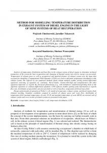
TEMPERATURE DISTRIBUTION IN AND AROUND ARRAY APPLICATOR FOR INTERSTITIAL MICROWAVE HYPERTHERMIA COMBINED WITH INTERSTITIAL RADIATION THERAPY Koichi Ito(1), Kazuyuki Saito(1), Takeshi Taniguchi(2), and Hiroyuki Yoshimura(1) (1)
(2)
Faculty of Engineering, Chiba University
Graduate School of Science and Technology, Chiba University 1-33 Yayoi-cho, Inage-ku, Chiba 263-8522, Japan E-mail:
[email protected]
ABSTRACT In recent years, various types of applications of electromagnetic techniques to microwave thermal therapy have been developed [1]. The authors have been studying thin coaxial antennas for the minimally invasive microwave thermal therapy, such as the interstitial microwave hyperthermia. In addition, hyperthermia can be combined with the radiation therapy and the chemotherapy [2]. Particularly, the combination of hyperthermia and interstitial radiation therapy is effective for the treatment of radiation-resistive tumors. In this study, we investigated the temperature distribution in and around the array applicator by numerical simulations. Moreover, the heating performances of the applicators are described under various conditions. INTRODUCTION In the recent few decades, various types of medical applications of microwaves have widely been investigated and reported. In particular, minimally invasive microwave thermal therapies using thin applicators are of a great interest. They are interstitial microwave hyperthermia and microwave coagulation therapy (MCT) [3] for medical treatment of cancer, cardiac catheter ablation for ventricular arrhythmia treatment, thermal treatment of BPH (Benign Prostatic Hypertrophy), etc. The authors have been studying thin coaxial antennas for the interstitial microwave hyperthermia. Besides, the combination of interstitial hyperthermia and interstitial radiation therapy is effective for the treatment of radiation-resistive tumors. In this study, we calculated the temperature distribution in and around the array applicator with on-off feeding control. Figure 1 shows the combined treatment system. This treatment system is realized by using common catheters between interstitial hyperthermia and interstitial radiation therapy. In this system, firstly, thin microwave antennas embedded in the catheter heat the tumor. After heating, only antennas are pulled out of the catheters. Then, a radiating source, such as the iridium 192, is automatically inserted into the catheters by a “high dose rate afterloading system”.
Interstitial microwave hyperthermia
Interstitial radiation therapy
Thin microwave antenna
Common catheter Radiating source Tumor
Fig. 1. Scheme of the combined therapy.
Tumor
ANTENNA ELEMENTS We used coaxial-slot antennas as the thin microwave antennas to constitute the array applicator. Figure 2 shows the basic structure of the considered coaxial-slot antenna. This antenna is made of a thin semirigid coaxial cable, whose outer diameter is approximately 1.0 mm. The tip of the cable is short-circuited and several number of ring slots are cut on the outer conductor. This time, we set two slots on the antenna as we have already confirmed that the coaxial-slot antenna with two slots generates a localized heating region only around the tip of the antenna [4]. We inserted the antenna to a catheter made of PTFE for hygiene. Moreover, this time, we added one more catheter to realize the combined therapy. The operating frequency is 2,450 MHz, which is one of the ISM (Industrial, Scientific, and Medical) frequencies. Common catheter Catheter Coaxial cable
Short-circuited Slots
1.19 1.79 2.55
2,450 MHz Human body
Unit: [mm]
140 Fig. 2. Basic configuration of the coaxial-slot antenna.
PROCEDURE OF CALCULATION In order to obtain a large heating region, we used an array applicator composed of a few antennas. Precisely we considered an array applicator composed of seven coaxial-slot antennas. In this paper, we analyze the heating characteristics of this array applicator by numerical simulations. First, we calculate the SAR (Specific Absorption Rate) distribution around the antenna from the following equation:
SAR =
σ 2 E ρ
[W/kg]
(1)
where σ is the conductivity of the tissue [S/m], ρ is the density of the tissue [kg/m3], and E is the electric field (rms) [V/m]. The SAR takes a value proportional to the square of the electric field generated around the antennas and is equivalent to the heating source created by the electric field in the tissue. The SAR distribution is one of the most important characteristics of antennas in terms of heating. Next, we calculate the temperature distribution in and around the array applicator. In order to obtain the temperature distribution in the tissue, we numerically analyze the bioheat transfer equation [5] using previously obtained SAR values by using the FDM (Finite Difference Method). The bioheat transfer equation is given by ∂T (2) ρc = κ ∇ 2 T − ρρ b cb F (T − Tb ) + ρ ⋅ SAR ∂t where T is the temperature [oC], t is the time [s], ρ is the density [kg/m3], c is the specific heat [J/kg·K], κ is the thermal conductivity [W/m·K], ρb is the density of the blood [kg/m3], cb is the specific heat of the blood [J/kg·K], Tb is the temperature of the blood [oC], and F is the blood flow rate [m3/kg·s]. Note that, we used an on-off feeding control to prevent overheat of the normal tissues. We set the temperature monitoring point around the array applicator and controlled the temperature between 42 and 45 oC at this point. TEMPERATURE DISTRIBUTION OF THE ARRAY APPLICATOR Figure 3 (a) shows the calculation model of the array applicator composed of seven coaxial-slot antennas and includes three temperature observation planes. Here, the antenna insertion depth and the array spacing are 70 mm and 15 mm, respectively. In order to provide enough microwave power for each antenna element, two microwave generators are used. The generators are not synchronous with each other (incoherent system) [6]. Figure 3 (b) explains the temperature monitoring point for the on-off feeding control. The parameters for calculation are listed in Table 1.
Figure 4 shows the calculated temperature distributions. In the graphs, the white doted lines represent the area which is more than 42 oC. The maximum lengths of the heating region, which is 42 oC or more, in the antenna insertion direction and in the vertical direction of the antenna insertion are approximately 20 mm and 40 mm, respectively. The size of the heating region depends on some parameters such as the blood flow rate, the input power of the antennas, the heating time, the scheme of the feeding, etc. In this paper, we present the dependence of the size of the heating region on the blood flow rate. In order to evaluate the size of the heating region, we introduce the following two indexes (see Fig. 5). • The maximum length of the area of 42 oC or more in the antenna insertion direction. We define this length as Hl. • The maximum diameter of the area of 42 oC or more in the vertical direction of the antenna insertion. We define this length as Hr. Figure 6 shows the results of the calculation. Figure 6 (a) and (b) show the dependence of these indexes on the blood flow rate with and without feeding control, respectively. From Fig. 6 (a), we can see that the value of the index is independent on the blood flow rate. On the other hand, in Fig. 6 (b), each value decreases while the blood flow rate increases. This is one of the merits of the on-off feeding control.
15 Fed by generator #1. Fed by generator #2.
Air
x
Muscle In the observation plane (iii)…
160
i y
z
80
iii 70 66
Temperature monitoring point
ii Unit: [mm]
(a) Calculation model. (b) Temperature monitoring point. Fig. 3. Array applicator composed of seven coaxial-slot antennas. Table 1. Parameters for the temperature calculations. Electrical properties (Muscle, 2,450 MHz) Relative permittivity 47.0 Conductivity [S/m] 2.21 Thermal properties Muscle Specific heat c [J/kg·K] 3,500 0.60 Thermal conductivity κ [W/m·K] 1,020 Density ρ [kg/m3] Blood Specific heat cb [J/kg·K] 3,960 1,060 Density ρb [kg/m3] Blood flow rate F [m3/kg·s] 8.33×10⁻⁶ Temperature of the blood Tb [oC] 37.0 Others Initial temperature [oC] 37.0 Heating time [s] 600 Net input power (total of the array) [W] 21.0
z [mm]
0
ii
i
[oC] 48
20
46
40
44 42
60
42 oC
38
80
iii
-20
20 y [mm]
x
40
Hl
20 0 y [mm] 42
y
z
oC
42 oC
0
Hr
-20 -20
20 0 x [mm]
Fig. 4. Calculated temperature distributions.
Fig. 5. Indexes for evaluation.
40 20
60 Hr Hl
Size [mm]
Size [mm]
60
40
Hr Hl
20
0
0 4.17 8.33 12.50 4.17 8.33 12.50 3 Blood flow rate F [m /kg·s] Blood flow rate F [m3/kg·s] (a) With the on-off feeding control. (b) Without the control. Fig. 6. Dependence of the blood flow rate with the size of the heating region.
CONCLUSIONS
In this paper, we described the heating characteristics of an array applicator aiming at the realization of a treatment system combing the interstitial microwave hyperthermia and interstitial radiation therapy. We introduced an array applicator composed of seven coaxial-slot antennas and employed an on-off feeding control. As a result, we can confirm that a heating region in and around the array applicator is generated. Moreover, we investigated the dependence of the size of the heating region on the blood flow rate. This kind of investigation is useful for actual treatments. Next, we plan to investigate a treatment that uses the results of this study. REFERENCES
[1] K. Ito, “Medical applications of microwave,” Proc. APMC’96, vol. 1, pp. 257-260, December 1996. [2] K. Ito, K. Saito, T. Taniguchi, S. Okabe, and H. Yoshimura, “Minimally invasive thermal therapy for cancer treatment by using thin coaxial antennas,” Proc. IEEE Annu. Int. EMBS Conf., October 2001. [3] K. Saito, Y. Hayashi, H. Yoshimura, and K. Ito, “Heating characteristics of array applicator composed of two coaxial-slot antennas for microwave coagulation therapy,” IEEE Trans. Microwave Theory Tech., vol. 48, no. 11, pp. 1800-1806, November 2000. [4] K. Saito, S. Okabe, T. Taniguchi, H. Yoshimura, and K. Ito, “Localized heating by using a coaxial-slot antenna with two slots for microwave coagulation therapy,” Dig. USNC/URSI National Radio Science Meeting, p. 422, July 2001. [5] H. H. Pennes, “Analysis of tissue and arterial blood temperature in the resting human forearm,” J. Appl. Phys., vol. 1, pp. 93-122, 1948. [6] L. Hamada, H. Yoshimura, and K. Ito, “A new feeding technique for temperature distribution control in interstitial microwave hyperthermia,” IEICE Trans. on Electron., vol. E82-C, no. 7, pp. 1318-1325, July 1999.