In order to find out the best possible compression achievable with compressors of ..... case, we can build templates specific to particular brands since order and ...
Template-based Signaling Compression for Push-To-Talk over Cellular (PoC) Andrea G. Forte and Henning Schulzrinne Department of Computer Science Columbia University {andreaf, hgs}@cs.columbia.edu
Abstract—The Session Initiation Protocol (SIP) has been chosen as the standard signaling protocol for the IP Multimedia Subsystem (IMS). SIP is a text-based protocol with messages often exceeding 1000 bytes in size, thus causing high call set-up delays on low bit-rate links. Signaling Compression (SigComp) is currently the only option cellular operators have for the compression of signaling messages. We study the performance of SigComp, showing that SigComp cannot achieve the level of compression required by Push-To-Talk over Cellular (PoC) services in the IMS. Furthermore, we propose an alternative compression mechanism, namely Template Based Compression (TBC), and show through measurements how we can achieve higher compression ratios than SigComp, satisfying the requirements for PoC on low bit-rate links.
I. I NTRODUCTION Push-To-Talk over Cellular (PoC) has seen a rapid growth in recent years. Various cellular carriers such as Nextel and Sprint offer PoC solutions usually combined with rich presence. PoC is a half-duplex technology that allows users to communicate with each other in a walkie-talkie fashion. Such communication can be point-to-point and point-to-multipoint. The IP Multimedia Subsystem (IMS) represents the next evolution in fixed and mobile network access and it is currently being deployed in many cellular networks. In the IMS, different access technologies converge under one single architecture based on the Internet Protocol (IP). This convergence allows for the delivery of Internet services regardless of the access network used. We can think of the IMS as an abstraction layer between the service layer and the transport layer. The IMS introduces many new network elements. For the purpose of this paper, however, we focus only on the User Equipment (UE) and the Proxy-Call Session Control Function (P-CSCF). The UE is the IMS end-point, while the P-CSCF represents the first point of attachment the UE has with the IMS. Once the UE connects to the IMS, its P-CSCF will remain the same for the whole duration of the IMS registration. The path between UE and P-CSCF usually includes a wireless link called the air link. In order to facilitate the integration between IMS and the Internet, the protocols used in the IMS were chosen from protocols standardized by the Internet Engineering Task Force (IETF). In particular, the Session Initiation Protocol (SIP) [1] was chosen as the signaling protocol for the IMS and it has been mandatory since release 5. Using SIP terminology, the
UE is the equivalent of a SIP user agent (UA) and the P-CSCF is the equivalent of a SIP proxy server. SIP was designed as a text-based protocol to simplify building new SIP-based services, create new SIP extensions and debug implementations. Since SIP was designed for high bit-rate links, the size of SIP messages did not really matter. For high bit-rate links, the size of SIP messages does not introduce a significant delay in the call set-up process. Things, however, change when we consider IMS. In the IMS we have different access technologies such as UMTS and GPRS that have significantly lower bit-rates than, for example, IEEE 802.11 and IEEE 802.16. In such cases, the large size of SIP messages significantly contributes to the call set-up delay, making the call set-up time too big for real-time applications such as voice and PoC. In order to address the large size of SIP messages and make SIP more “friendly” for low bit-rate links, the IETF standardized a general compression framework called Signaling Compression (SigComp) [2]. SigComp provides a high degree of flexibility in that it can support any type of dictionary-based compression algorithm, but it does so by sacrificing performance (see Section IV). By using SigComp, SIP messages are in many cases significantly shorter than their uncompressed version. This, however, is still not enough for applications such as PoC where the Post Dial Delay (PDD) has to be on the order of one second or less (see Section VI). The main contributions of this paper are listed below. • We study and evaluate SigComp performance for different SIP flows and show the call set-up delay for each. • We show how SIP introduces the largest contribution to the call setup delay. In particular, in our measurements, the exchange of SIP messages took several seconds to complete. • SIP affects only one component of the total call setup delay, that is, the air-link delay. Because of this, a SigComp-based solution is limited since it does not improve on other components of the call set-up delay such as the air-link setup delay. • SigComp has intrinsic limitations due to its architecture in order to achieve a high degree of flexibility. We analyze such limitations and show why SigComp is not suitable for achieving very high compression for smaller packets. • We analyze compression techniques based on text substitution such as those of the Lempel-Ziv (LZ) family,
pointing out limitations and shortcomings relevant to the present context. • We introduce a new compression mechanism based on the concept of templates called Template Based Compression (TBC) that cellular operators can use in their network. We show how such mechanism makes it possible to achieve the delay requirements of the most time-critical applications such as PoC in the IMS. We compare the performance of the proposed compression mechanism with those of SigComp and show how the proposed compression mechanism always outperforms SigComp. • Finally, we show how including our compression mechanism within the SigComp architecture is not desirable since SigComp becomes counter-productive as the size of messages becomes smaller. The rest of the paper is organized as follows. In Section II we present current approaches for compressing signaling messages and Section III describes the delays in the IMS for call setup. In Section IV we describe SigComp operations, pointing out advantages and disadvantages and in Section V we introduce TBC. Section VI shows and compares performance of SigComp and TBC. Finally, Section VII concludes the paper. II. R ELATED W ORK The use of compression in network protocols is not new. Header compression such as Robust Header Compression (ROHC) [3] is used for the compression of protocol headers; Transport Layer Security (TLS) [4] and File Transfer Protocol (FTP) [5] have a compressed transmission mode and IP compression (IPComp) [6] is used to compress IP datagrams. All of these compression protocols, however, are not suitable for compression of application layer messages and while they can complement a compression mechanism at the application layer, they cannot replace it. In particular, TLS and IPComp use LZ-based compression for messages at the transport and IP layer respectively, without discerning between applications. This makes LZ-based compression less efficient since application-specific redundancy cannot be fully exploited. Signaling compression, is relatively new and has attracted more interest in recent years, especially after SIP became the signaling protocol for the IMS. SigComp [2], a general framework for signaling compression, was standardized by the IETF in 2005. We present the SigComp architecture in Section IV and compare it with our approach throughout the paper. In [7], Akhtar et al. introduce a new entity called Encoding Assistant (EA) on both the UE and the P-CSCF. The EA is placed between the application layer and the SigComp layer and takes care of compressing some of the dynamic content of SIP messages such as SIP Uniform Resource Identifiers (URIs). Together with the EA, new SIP option tags and new SIP headers are introduced. The EA inserts new headers in the SIP message to be compressed. These new headers contain an index value that points to a particular entry in the Identity List. The Identity List is a list of maximum 16 entries containing identity information for a specific user. This list
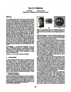
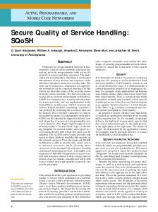
is used for indexing the content of the Via, From, Contact and P-Preferred-Identity headers. The use of an indexed list aims to reduce the size of the message by replacing a string with a number. This advantage, however, is not significant since the new headers added to contain this index are 14 bytes long or more. The performance of such mechanism have not been proven. Furthermore, SigComp Extended Operations [8] introduces the concept of User Specific Dictionary (USD) which offers similar functionalities to the ones of the EA in that it allows for a better compression of the dynamic content specific to each user, and this without the introduction of any new header or tag. Because of this, we see little or no use in adopting the proposal in [7]. Viamonte et al. in [9] introduce the concept of Session Description Protocol (SDP) template for reducing the session setup delay for streaming services using the Real-Time Streaming Protocol (RTSP). Here, the streaming server builds a template for the SDP part of the RTSP packet. This template contains all the SDP fields present in the packet and their values. Those SDP fields whose value is not known when the template is built, are still present in the template although empty. For those SDP fields that are empty in the template, their value is sent in the 200 OK answering the RTSP DESCRIBE request. In such case the order of the variables in the 200 OK has to be the same as in the template. Each field is not split in a variable part and a fixed part; it is either completely present in the template or it is sent later. The server sends to the client a URL where to download the template. When the template is no longer applicable because some parameters have changed, the server will send the client a new URL where to find the updated template. The approach proposed in [9] can be seen as a specific case of our TBC, although with some important differences. In [9] the way the template is built and used is specific to the characteristics of streaming sessions and it addresses only SDP content for RTSP messages. Many parameters that we consider as variable such as codecs and port numbers, are considered as constant and therefore part of the SDP template. Furthermore, new headers advertising the support of SDP templates and the URLs where to download such templates are included in packets exchanged during timecritical operations. This introduces the possibility of SDP templates negatively affecting the session setup delay. In TBC, information regarding templates is never sent during timecritical operations, hence TBC always improves the setup delay. Finally, the variable fields not included in the SDP template are sent in the 200 OK without any encoding. In TBC we encode variable content that is not included in the template to further improve compression. III. D ELAYS IN THE IMS In terms of delay we look at the call setup delay and PDD. The call setup delay is the time between the INVITE request and the 200 OK. The PDD is the time from when users press the “call” button to when they receive the ring-back, that is, the 180 Ringing (see Fig. 1).
User A
User B
P-CSCF
Application Layer (SIP)
REGISTER
REGISTER
200 OK
200 OK
Application message + Compartment ID
Call Air link setup
INVITE
Compressor Dispatcher
Air link setup
Decompressed message
Compartment ID
Compression
Decompression
State
State
State Handler
State Handler
State
State
Decompressor Dispatcher
183 PROGRESS Post Dial Delay (PDD)
PRACK
Compressor 200 OK (PRACK)
UPDATE
Compressor
UDVM
200 OK (UPDATE) 180 RINGING
SigComp Message
SigComp Message
PRACK
Ring back 200 OK (PRACK)
Answer
Transport Layer (UDP, TCP, ...)
200 OK (INVITE) Bearer path established
Fig. 1.
Fig. 2.
SIP flow for call set-up
Generally speaking, users do not embrace a new service when this new service offers performance inferior to the service it replaces. This is the case of a GSM network and an IMS-based wireless network, for example. In a GSM network the typical call set-up delay is 2 seconds for a mobile-toPSTN call, 2.2 seconds for a PSTN-to-mobile call and about 4 seconds for a mobile-to-mobile call1 [10]. As we show in Section VI, in the IMS, the air-link delay alone can be as high as 7 seconds. SigComp reduces air-link delay down to about 2 seconds. SigComp, however, improves only on the air-link delay, leaving other causes of delay unaffected. This makes a SigComp-only approach not sufficient for real-time applications such as PoC where PDD has to be on the order of one second or less. Fig. 1 shows a typical call set-up flow for a SIP UA in the IMS. For each packet we have to consider the following delays: air-link setup delay, node processing delay, long distance and back-hauls delay, and air-link delay. The one-way end-to-end delay is given by: up down δ = N · (TAD + TAD + Tnode + TBH ) + Tsetup
(1)
with
L RT T + (2) R 2 up where N is the number of packets transmitted, TAD is the down air-link delay for the uplink, TAD is the air-link delay for the downlink, Tnode is the node processing delay, and TBH is the back-hauls delay. Finally, Tsetup is the air-link setup delay which is the time needed to setup the air-link before the first message can be sent and/or received on the data channel. Tsetup is usually 1400 ms, that is 700 ms on the sender side and 700 ms on the receiver side (see Fig. 1). In Eq. (2), L is the message size, R is the link bit-rate and RT T is the RoundTrip Time. Throughout our calculations we assume the RT T to equal 140 ms [11]. up down TAD ≡ TAD =
1 GSM uses Signaling System No.7 (SS7), a bit-field-encoded signaling protocol.
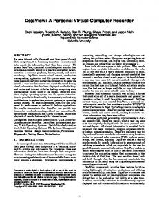
Architecture of a SigComp end-point
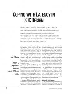
SigComp helps in reducing the overall call set-up delay up down . Other delays and in particular by reducing TAD and TAD Tsetup are not affected. We focus our attention on Tsetup because Tsetup is responsible for a significant part of the total delay. In particular, Tsetup can be removed if at call set-up time the control channel can be used instead of the data channel. This, however, means that, for 1xEV−DO rev. A, the first INVITE and subsequent packets need to be no larger than 211 bytes for the uplink and no larger than 113 bytes for the downlink [7]. As we show in Section VI-B, SigComp cannot compress the INVITE down to the required sizes, while TBC can. IV. S IGNALING C OMPRESSION (S IG C OMP ) A. Overview Figure 2 shows the architecture of a SigComp end-point. We can consider SigComp as a new layer between application layer and transport layer. In particular, resources in SigComp are assigned based on compartments. A compartment is a particular grouping of messages that is specific to a particular application. In SIP, a compartment can be identified with a dialog. When an application wants to use SigComp, it has to provide the application message to compress and a unique compartment identifier. Messages belonging to the same SIP dialog have the same compartment identifier. This unique identifier is used by the SigComp layer to allocate resources such as state memory, Universal Decompressor Virtual Machine (UDVM) memory and compressor and also to access previous state. The main component of the SigComp architecture is the UDVM which is a normal virtual machine, like the Java virtual machine, but optimized for decompression operations. The UDVM machine language is called bytecode and it is used to implement decompression algorithms that the UDVM has to run in order to decompress messages. Other components of the SigComp architecture are the Compressor Dispatcher, Decompressor Dispatcher, and the State Handler.
0
1
2
3
4
5
1
1
1
1
1
T
6
7
0
1
2
3
4
5
1
1
1
1
1
T
6
7
0
returned feedback item
len
code_len returned feedback item
code_len
destination
partial state identifier
uploaded UDVM bytecode
remaining SigComp message
remaining SigComp message
(a) With previous state
(b) With UDVM bytecode
Fig. 3.
Fig. 4.
Compression based on text substitution
TABLE I F IRST PHASE OF LZ COMPRESSION FOR THE FIRST INVITE REQUEST (A LL VALUES IN B YTES ) Original size From previous messages From itself Not found
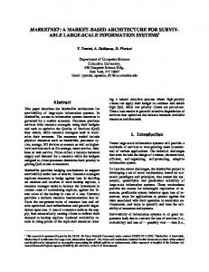
Format of a SigComp message
Short Flow 1350 790 577 395
Long Flow 1253 989 596 212
B. Overhead SigComp was designed so that it would not be tied to a specific compression algorithm. This flexibility, however, introduces a cost in terms of complexity and packet size. Aside from the performance of the particular compression algorithm used, SigComp has some significant drawbacks that do not make it the best choice when the size of the compressed packets needs to be very small. Fig. 3 shows the structure of a SigComp packet. All the fields other than the remaining SigComp message field form the packet header. Fig. 3(a) shows a SigComp message when a previous saved state is accessed on the remote end-point. Fig. 3(b) shows a SigComp message that does not point to a previous saved state but rather contains the UDVM bytecode. Also, SigComp uses a feedback mechanism to facilitate the exchange of state-related information and other parameters between compressor and UDVM. As we can see, SigComp introduces various headers, adding to the total packet size. The feedback item can have a size of up to 128 bytes and the UDVM bytecode can be of variable length as specified in the code len field. Its size can be anywhere between 0 and 4095 bytes. All of this clearly shows how even one single feedback item may compromise any compression effort aimed to reach the size requirements specified in Section III. C. Compression SigComp uses compression based on text substitution such as Lempel-Ziv 77 (LZ77) and Deflate2 . Figure 4 shows the basic idea behind this family of compression algorithms. As we can see, the compression is based on the construction of an adaptive dictionary containing a number of unique strings. Every time a new string that is not present in the dictionary is found in the look-ahead buffer, it is added to the dictionary. Any occurrence of any string already present in the dictionary is replaced with an {offset, length} pair which points to the same string in the adaptive dictionary. In this way, string repetitions are replaced by {offset, length} pairs. The longer the string replaced and the more frequent the repetitions, the higher the compression. 2 Deflate uses LZ77 for the elimination of duplicate strings and Huffman coding for bit reduction.
Unfortunately, this kind of compression has several drawbacks. •
•
•
The initial compression is low. At the beginning of a sequence, the adaptive dictionary has yet to be built and the frequency of string repetitions is low. Static dictionaries such as the SIP static dictionary [12], can help in reducing this problem. Their use is however very limited due to the fact that the information they provide helps only for the very first stages of the compression process while consuming a significant amount of resources. Many SigComp implementations, such as Open SigComp [13], do not use static dictionaries for compression. It is inefficient for smaller sequences. Usually, short sequences have fewer string duplicates. The longer the sequence to compress, the higher the probability of finding string duplicates. It is inefficient for short strings. For very short strings, the pair {offset, length} can take more bytes than the actual string it is replacing. In Deflate, for example, string duplicates that are shorter than four bytes are ignored.
In order to find out the best possible compression achievable with compressors of the LZ family, we performed some preliminary measurements on two types of IMS flows, a short flow and a long flow. The short flow follows the basic SIP call setup flow (REGISTER→200→ INVITE→180→200→ACK), while the long flow is similar to the one shown in Fig. 1, but with multiple messages exchanged also before the INVITE request. We implemented the first phase of LZ-based compression, that is, identify if a string or sub-string had ever been encountered before in either the same packet or previous packets. In our implementation we use the same convention as in Deflate, that is, strings of three bytes or shorter are considered as not found in the adaptive dictionary. Furthermore, we do not limit the size of the adaptive dictionary, so that older state is not discarded because of newer state. As we can see from Table I, for the short flow we found that for the first INVITE request, 395 bytes out of 1350 bytes were not found in both previous lines of the same packet and in previous packets. For the long flow more repetitions
were found and only 212 bytes out of 1253 bytes were not found. This shows that if we apply LZ to the first INVITE, in theory, we have at best a compressed size of 395 bytes for the short flow and 212 bytes for the long flow. In reality, the compressed size is bigger for both flows since we have to consider the extra bytes that each {offset, length} pair takes, plus the size of the adaptive dictionary which is included in the compressed packet. Furthermore, in reality the adaptive dictionary is limited in size, eventually causing loss of older state, thus increasing the overall number of bytes not found. Although Huffman coding might help to push compression a little further, it is clear that compressing a message that is 1300 bytes long to about 100 bytes or less is not possible with LZ-based compression. D. SIP Static Dictionary The use of the static dictionary improves the compression ratio for the initial messages by providing some initial content for the adaptive dictionary that would otherwise be empty. As we will see in Section VI-B, not using a static dictionary leads to a compression ratio above 100% for the initial messages. This happens until sufficient state is built. A compression ratio above 100% means that the size of the compressed messages is larger than the one of the original messages. Typically, however, this happens only for the initial REGISTER−200 OK handshake. The SIP static dictionary has a size of 3468 bytes. After a few messages have been exchanged within the same dialog, most or part of the static dictionary is replaced in the state memory by more recent state and compression is performed according to the new state. The added complexity and the fast aging of state based on the static dictionary make the use of static dictionaries very limited, with many implementations not supporting them at all. Furthermore, static dictionaries improve the compression of only the very first messages of a flow, typically the initial REGISTER−200 OK handshake, leaving time-critical messages unaffected. Because of all of these reasons, static dictionaries are not used in our experiments. E. Extended Operations SigComp Extended Operations are defined in RFC 3321 [8]. New mechanisms are proposed in order to further improve compression. All the proposed mechanisms try to improve on how state is created and destroyed so that unnecessary state deletions are avoided and new state is created more efficiently. Some of the mechanisms proposed in [8] are dynamic compression, shared compression, User Specific Dictionary (USD) and implicit deletion for dictionary update. Of all the proposed mechanisms, USD is the most relevant to the present context. USD is a dictionary built on the assumption that a {user, device} pair produces, over time, the same content for those headers in a SIP message related to the capabilities of the device or to the user. USD, however, still uses the typical conventions of LZ-based compression algorithms. It just represents a different dictionary used in the LZ-based compression.
Because of this, although USD improves on the compression of dynamic content, it still suffers from all the drawbacks previously discussed for LZ-based compression. This limits the improvements achievable with USD. Moreover, the way the USD is built and how it is exchanged between SIP entities is not standardized and as of the writing of this paper, SigComp implementations supporting Extended Operations are not available. For all of these reasons, and because of the limited improvements that USD would introduce, we do not consider USD or any of the mechanisms proposed in [8] in the rest of the paper. F. Advantages and Disadvantages To summarize, the advantages in using SigComp are that it has already been standardized by the IETF, is mandatory in the IMS and there are already implementations available such as Open SigComp [13]. The disadvantages are that it is very complex and heavy, LZ-based compression is not enough for many delay sensitive applications such as PoC. Furthermore, SigComp introduces significant overhead regardless of the compression algorithm used. V. T EMPLATE -BASED C OMPRESSION (TBC) As we have explained in Section III, in order to significantly reduce the call setup time and PDD, we need to compress the messages so to achieve a maximum size of 211 bytes for the uplink and 113 bytes for the downlink. This is because we do not only want to reduce the air-link delay, but we also want to remove the air-link setup delay (see Eq. (1)) and in order to remove the air-link setup delay, we need to send the Data Over the Signaling channel (DOS). As we show in Section VI, SigComp cannot satisfy the message size requirements for DOS while TBC can. In this section we describe how TBC works. A. Overview The basic idea behind TBC is that the content of many headers and SDP parameters in a SIP message does not significantly change over time. There are headers that do not change at all throughout different sessions, there are headers that do not change within a session and there are headers whose value changes on a per-call basis. By using these characteristics of SIP headers and SDP lines, we build templates for SIP messages. A template contains the part of a message that is likely not going to change. In doing so, UE and P-CSCF need to exchange only the variable parts of a message so that the template can be “filled in” and the whole SIP message can be correctly re-constructed at both the UE and P-CSCF. By using templates we reduce the amount of information that needs to be exchanged between UE and P-CSCF. Also, in order to minimize the message size as much as possible, we encode such information. Templates can be exchanged ahead of time-sensitive operations such as during registration. When the P-CSCF has to send an INVITE to a UE, it checks its outgoing-INVITE
template for that particular UE. The P-CSCF extracts from the INVITE the variable content that is not present in the template and encodes it. The encoded values are then put in the final packet following a specific order and the final packet is sent to the UE. The ordering of the encoded values is very important since it allows the UE to know which value belongs to which header in the template. After receiving the encoded packet, the UE extracts the encoded values from the packet, decodes them and matches them to the corresponding headers in the incoming-INVITE template. In doing so, the INVITE has been successfully re-constructed. The same process is performed in the other direction, from the UE to the P-CSCF. TBC compresses a message in the following steps: 1) Header Stripping. Unnecessary headers are stripped from the message. 2) Template. The message is filtered according to a template so that only the dynamic content not present in the template is extracted from the message and eventually sent to the remote end-point. 3) Shared Dictionary. The Shared Dictionary (SD) is searched for matching strings among the ones present in the dynamic content extracted at step 2. If a match is found, the string is replaced by the corresponding index in the dictionary. 4) Encoding. The dynamic content is encoded so to occupy the minimum number of bytes. Only after all of the above steps have been completed, the message is ready to be sent. We now look in more detail at each one of the previous steps. B. Header Stripping Some SIP headers are present only in incoming messages while others are present only in outgoing messages. For example, headers such as Route, Security-Verify, PPreferred-Identity, Proxy-Require are present in outgoing INVITE requests but not in incoming INVITE requests. On the other hand, headers such as Record-Route and P-AssertedIdentity are present in incoming INVITE requests but not in outgoing ones. This classification helps us in knowing what headers to expect when building a template for an outgoing or incoming SIP message. Furthermore, there are headers whose value is relevant only to SIP proxies and not to SIP UAs. If we assume SIP end-points to act as a SIP UA, for packets sent by the P-CSCF to the SIP UA we can safely ignore such headers. In order to exploit this behavior, before building a template, SIP headers that are not relevant to a SIP UA are removed from the message by the P-CSCF. Some of the headers that we strip from a SIP message are shown in Table II. Let us consider, for example, the case of the Via header for an incoming SIP INVITE. The Via header in this case is populated with all the SIP proxies the message has traversed in order to reach its destination. This is done so that the response to the SIP INVITE can follow the same path of the SIP INVITE itself. However, all the information the UA really
TABLE II ACTIONS ON SIP HEADERS Header Max−Forwards Via User−Agent P−Alerting−Mode Record−Route Session−Expires Supported Privacy Require Allow
Stripped (UA as receiver) X X X X X
SW/HW dependent
Token
Typical values
X X
X X X X
X
X
1800, 3600 100rel, timer None, id Precondition REGISTER, BYE, INVITE, . . . *;+g.poc.talkburst; require;explicit Application/sdp, mulitpart/mixed Application/sdp, text/html
Accept−Contact
X
Content−Type
X
Accept
X
needs is the first hop where to send its response, that is, the IP address of the P-CSCF the UA is currently attached to. The UA already has this information, therefore the P-CSCF does not need to send the content of the Via header to the UA. The response to the incoming INVITE sent by the UA will have a Via header containing only the address of its P-CSCF. The P-CSCF will then make sure to re-insert all the missing entries from the Via header received in the initial incoming INVITE into the UA response when re-constructing the packet for such response. C. Templates Generally speaking, we can classify SIP headers into four categories: • Variable: headers that can change between calls. • Semi-variable: headers that are session or registration dependent. • Semi-constant: headers that are device dependent in either hardware, software or both. • Other: all those headers that do not belong to any of the previous groups such as headers that change within a dialog. Furthermore, there are headers that occur more frequently than others and there are headers that are present only in requests and headers that are present only in responses. All of these factors need to be taken into consideration when defining a TBC mechanism for SIP messages. The construction of a template for a particular SIP message is based on the header classification that we have just introduced. In particular, headers belonging to the group of semi-constant and semi-variable are included in the template together with their value. Headers belonging to the group of variable and other are included in the template without any value. The content of those headers whose value is not included in the template represents the dynamic information that has to be sent on the air. Mixed situations are also possible where a semi-variable header, for example, can have a single parameter whose value is part of the dynamic content. For semi-variable headers, templates can be updated between registrations to reflect a change in their value. Semi-
constant headers allow us to tailor templates according to a particular hardware device or piece of software. In this last case, we can build templates specific to particular brands since order and header fields do not change for devices of the same brand. For example, if a device is running the Columbia University SIP client, we know to use the templates for Columbia University or if a device is a Linksys device, we know to use the templates for the Linksys brand. Without the notion of software/hardware-dependent headers we would not be able to consider as constant many headers that indeed can be considered as such. Table III lists a sample number of SIP headers and their classification as discussed above. Their frequency of use is also shown. Templates for outgoing messages and incoming messages are different even though the type of message is the same. This is because for an outgoing INVITE request, for example, the number of headers whose value is known is much higher than for an incoming INVITE request. An incoming INVITE request can come from anywhere and anyone, therefore the a priori knowledge we have on such INVITE request is small.
TABLE III C LASSIFICATION OF SIP HEADERS Header Accept Accept−Contact Accept−Encoding Accept−Language Alert−Info Allow Authorization Call−ID Call−Info Contact Content−Disposition Content−Encoding Content−Language Content−Length Content−Type CSeq Date Expires From In−Reply−To Max−Forwards Record−Route Route Session−Expires Supported To User−Agent Via
Variable (call dependent)
Semi−var (session or registration dependent)
Semi−const (HW/SW dependent)
Other (variable within dialogue)
X X X X X X X X X X X X X X X X X X X X X X X X X X X X
Occurrence
medium high (PoC) low low low high low high low high low low medium high high high low medium high low high high high high high high high high
D. Shared Dictionary (SD) A dictionary is an ordered collection of strings. The use of a dictionary is very convenient for compression because by using a dictionary we can replace a string with its corresponding index in the dictionary. Naturally, for things to work correctly at decompression time, the dictionary used for decompression needs to be an exact copy of the one used for compression so that the same index corresponds to the same string. If this does not happen, we have a decompression failure. Decompression failures are discussed in Section V-G. As we can see from Table III, many of the SIP headers belong to the group of variable headers. Many of these contain a URI. This URI can be related to one of the UA public identities (i.e., P-Called-Party-ID) or to another user. Other sources of variable headers comprise the codecs included in the SDP part of the SIP message together with rtpmap lines and the codecs’ fmtp parameters. Here, we use a dictionary in order to reduce the amount of bytes that URIs and codecrelated parameters take. As we said earlier, a dictionary is simply an ordered list of strings containing all the URIs known to the UA or P-CSCF (i.e., own URIs and URIs of other SIP entities), the list of codecs with both static and dynamic payload types and all known rtpmap and fmtp lines. If a match is found in the dictionary, the corresponding string is replaced by its index in the dictionary; if no match is found then the string is left as is. In the latter case, such string would be added to the dictionary by both UA and P-CSCF, as the last entry in the dictionary. In this way, this new entry can be used for future packets. There are many possible ways to build such an SD. In a typical scenario, users want to start a PoC session with contacts present in their presence “buddy list”, that is, people they already know. In order to build a dictionary containing
URIs of other end-points, such as a shared address book, we could think of the following. When the P-CSCF has an INVITE request to send whose URI in the From header is not present in the dictionary, it adds the URI to its dictionary and replaces it with its index. When the UA receives such INVITE, it does not find that particular index in its dictionary, so it associates the index received in the From header to that SIP dialog. When the P-CSCF sends the ACK in response to the 200 OK, the UA extracts the URI from the From header of the ACK and associates it to the index previously saved for that dialog. In doing so, the UA has added a new entry to its dictionary. Further details on how to build synchronized dictionaries is reserved for future study. E. Encoding By using templates, UA and P-CSCF need to exchange only the content of those headers that are without a value in the template, that is, the dynamic content of a SIP message. However, as we show in Section V-F, even exchanging only the dynamic content of a message is not enough to achieve the requirements for DOS. In order to achieve such requirements the dynamic content needs to be encoded to further reduce the size of messages exchanged between UA and P-CSCF. Variable content can be encoded using integer and bitwise representations. We can apply the latter to all those headers whose values belong to a finite set of known elements (see Token column in Table II). In order to encode strings such as IP addresses, port numbers, and clock rates, we encode these as fixed and variable length integers. For example, an IP address can be encoded as a four byte integer and a port number can be encoded as a two byte integer. Dictionary
TABLE IV C ONTRIBUTIONS TO TBC FOR AN INVITE REQUEST
Packet size [Bytes] Removed [Bytes]
Original Packet 1182 −
Stripped Headers 1008 174
Template
SD
Encoding
343 665
284 59
137 147
Packet Order 81 56
indexes can be encoded as variable-length integers depending on the cardinality of the number to encode. One other important aspect to take into consideration is the structure of the final packet. Once all the content has been encoded, the way such content is organized in the final packet also affects the size of the packet. In particular, we divide the packet in two parts. In one part we put all the encoded content of variable length and in another part we put all the encoded content of fixed length. The fixed-length content forms the last line of the packet. Each line in the packet has the first byte representing its length. The byte representing the length is also encoded. In particular, only 7 bits are used to represent the length of a line which limits the maximum length to 127 bytes. The most significant bit (MSB) is used to indicate if the following line is of the same type of the current line. This, for example, is useful if we have a SIP message with two or more c= lines in the SDP part. Since the order of variables in the packet has to be preserved, we need to explicitly mark those variables not present in the message but whose header is present in the template, as empty. In order to do this, we reserve one value of the byte representing the length of the line to indicate a length value of zero. Such value is given by the MSB set to one and all the remaining 7 bits representing the length, set to zero. F. Contributions to Compression Table IV shows how each of the mechanisms described above contributes to the overall compression. As we can see, each one of them has a significant role in the overall compression. In particular, the table shows the results for an incoming INVITE request. In the experiments all heuristics were applied so that, for example, the size shown for Template reflects the size of the packet after both Stripped Headers and Template have been applied. The Removed row shows how many bytes were removed from the message after applying the corresponding technique. In conclusion, from Table IV we can see that with TBC, we can satisfy the requirements for DOS, but in order to do this all the proposed techniques need to be applied. G. Decompression Failures TBC relies on the use of a shared dictionary in order to achieve maximum compression. In order for this to work, it is important that UE and P-CSCF keep their dictionaries synchronized at all times. A loss in dictionary synchronization almost certainly translates in a decompression failure at either end-point. A decompression failure is a very expensive event. When it happens, it requires the packet to be re-transmitted uncompressed and subsequent packets to be transmitted without compression until the cause for the decompression failure
has been resolved. Because of this, a sanity check should be performed periodically in order to validate the synchronization of the dictionary. In any event, if a loss in synchronization happens, it has to be detected in a timely manner so that it can be quickly resolved. Loss in synchronization between dictionaries can happen for various reasons. For example, when using non-reliable transport, we have to be careful to the way the shared dictionary is built. If packets used to build the dictionary are lost or end up out of sequence, we might end up with dictionaries that are not synchronized. It is important to notice that this problem is not present when we use the INVITE−ACK procedure described earlier for building the dictionary. In such a case, if an ACK is lost, the 200 OK would be re-transmitted thus triggering another ACK. In order to verify the synchronization of the shared dictionary we can use a short checksum such as Cyclic Redundancy Check 16 (CRC−16). This checksum is calculated on the message to send, after stripping the unnecessary headers but before applying the template. Once the message is received and re-constructed at the other end-point, the UE or P-CSCF can re-calculate the checksum and see if it matches with the checksum received with the message. If there is a mismatch it means that the reconstructed message is different from the original message, which means that the dictionaries have lost synchronization. Another way to verify the synchronization of the shared dictionary is to compute an hash of the dictionary and have UE and P-CSCF periodically exchange it during non-timesensitive operations. If the two hash values do not match, the shared dictionaries are not synchronized. In order to identify which part of the dictionary is out of sync, a binary search can be performed on the dictionary, recursively hashing smaller parts of it until the one or more entries responsible for the mismatch are found. Once a loss in synchronization has been detected and the non-aligned entries have been identified, the dictionaries can be re-synchronized by having UE and P-CSCF exchange such non-aligned entries. VI. E XPERIMENTS In this section we present the results of our experiments for SigComp and TBC. We consider both Mobile Originated (MO) calls and Mobile Terminated (MT) calls. An MO call is a call initiated by the mobile node, that is, by a mobile SIP UA. For such call, the first INVITE request is sent by the mobile SIP UA to the P-CSCF and then forwarded to the remote SIP UA. An MT call is a call initiated by a remote SIP end-point. In this case, the first INVITE request is sent by remote SIP UA and forwarded to the appropriate P-CSCF which sends it to the mobile SIP UA. A. Experimental Setup For our experiments, we used an IBM T42 Thinkpad laptop with a 1.7 GHz Pentium Mobile processor and 1 GB of RAM and an eRack server with a 3 GHz Pentium 4 processor and
1387
1350
1033
1400
499
476
461
400
487 483 418
656
599
590
486
478
143
201
182
600
362 219
207
169
800 723
60
315
200
626 80
63
219
143
264 161
289
215
27
220 261 103
90
52
E n a G IS ut TE ho R R riz EG ed IS 20 TER SU 0 O S K C R 20 I BE 0 N OK O TI 20 FY 0 18 O 3 IN K S es 10 VI s i 0 T TE on r Pr yi ng og 20 re 0 O PR ss K (P A C R K 20 A 0 O UP CK) K ( U DA PD TE 18 0 AT R E) in 20 gi 0 O PR ng K 20 A ( C P 0 O RA K K (IN CK VI ) TE AC ) K B 20 Y E 0 O IN K VI TE U
40 1
Compression ratio
106
54
1899
51
604
585
524
673
602
161
215
215 261 98
90
519 50
270 27
BY 20 E 0 O K
674
422 264
0
1051 100
586
556 532
500
257 222
1052
974 811 607
519
200
150
Bytes 1000
1889
41
257 137 131
25
28
52
39
0
32 0
42 0
42 0
B
B
ad
1500
50
292 148
BY 20 E 0 O K IN 10 VIT E 0 T 18 ryi n g 0 R in gi n 20 g 0 O K AC K
IS Ex TER te n R s ion EG IS TE 20 R 0 O K IN 10 VIT E 0 Tr y 18 0 i ng R in gi n 20 g 0 O K AC K
EG
150 % 602
0
R
2000
IS Ex TER te n R s ion EG IS TE 20 R 0 O K IN 10 VIT E 0 T 18 ryi n 0 R g in gi n 20 g 0 O K AC K
673
422
500
Compressed size
250
ad
585
524
20 35 0
EG
604
200
R
674
40
215
R
E n a G IS ut TE ho R R riz EG ed IS 20 TER SU 0 O S K C R 20 I BE 0 N OK O TI 20 FY 0 18 O 3 IN K S es 10 VI s i 0 T TE on r Pr yi ng og 20 re 0 O PR ss K (P A C R K 20 A 0 O UP CK) K ( U DA PD TE 18 0 AT R E) in 20 gi 0 O PR ng K 20 A 0 (PR CK O A K (IN CK VI ) TE AC ) K B 20 Y E 0 O IN K VI TE
R
U
586
556 532
2500
100
811 607
250
1051
963
219
66 31 52 40 33 25 20 27 23 28
0
40 1
Bytes
1052
219
60
SigComp performance for an MO call (long flow)
1889
974
402
362
(b) SMS: 8192, CC: 64, UMS: 8192
1500
1000
80
590
486
207
169
Original size
2500
1899
599
430
63
Compression ratio
Fig. 5.
487 476 419
201
182
(a) SMS: 4096, CC: 64, UMS: 4096
2000
461
36 0
Compressed size
476
656
315
200
20
0
Original size
656 499
100
745
400
40
215
68 39 52 39 33 25 20 27 23 30
852
785
%
656
900
888
120
961
BY 20 E 0 O K
600
100
745
Bytes
800 723
1000
852
785
160 140
1033
120
961
900
888
180 1387
1350
1338
1200
%
Bytes
1600
160 140
1200 1000
180
BY 20 E 0 O K IN 10 VIT E 0 T 18 ryi n 0 g R in gi n 20 g 0 O K AC K
1338
1400
%
1600
Original size
Compressed size
Original size
Compression ratio
(a) SMS: 4096, CC: 64, UMS: 4096 Fig. 6.
Compressed size
Compression ratio
(b) SMS: 8192, CC: 64, UMS: 8192 SigComp performance for an MT call (short flow)
1 GB of RAM. The T42 runs Linux kernel version 2.6.3-25 and the eRack runs Linux kernel version 2.6.9-42. The T42 behaves as an UE and the eRack as a P-CSCF. Both, UE and P-CSCF, read a SIP flow from a text file and exchange the compressed messages respecting the order of the packets in the flow. In order to test TBC and SigComp in realistic scenarios, all the IMS SIP flows used in the experiments were captured from a real IMS testbed and provided to us by Nortel. We used Open SigComp [13], an open-source SigComp stack and implemented a TBC compressor and decompressor. Compression for both MO and MT calls was measured and delays were later calculated according to Eq. (1). B. Measurement Results In the following measurements we focus our attention only on SIP messages and do not consider lower-layer protocol headers (e.g., UDP, IP). Such headers are not really relevant for PoC purposes and protocols like ROHC can help in their compression.
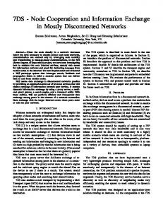
1) SigComp: As explained in Sections IV-D and IV-E, in analyzing SigComp performance we do not use the SIP static dictionary and also, do not consider any of the mechanisms specified in [8]. Furthermore, we perform measurements for the most common values of state memory size (SMS), CPU cycles (CC) and UDVM memory size (UMS). Figs. 5 and 6 show the compression ratio that SigComp can achieve for an MO call and an MT call, respectively. Figs. 5(a) and 6(a) show the results for SMS, CC and UMS equal to 4096 bytes, 64 cycles and 4096 bytes, respectively. Figs. 5(b) and 6(b) show results for SMS, CC and UMS equal to 8192 bytes, 64 cycles and 8192 bytes, respectively. The compression ratio is calculated as: ρ =
size of compressed packet [bytes] size of uncompressed packet [bytes]
(3)
so that the smaller the compression ratio, the better. As we can see from Figs. 5 and 6, ρ for the first two messages is above 100%. This happens because the size of the compressed packet
TABLE V PARAMETERS USED IN DELAY CALCULATION ( SOURCE N ORTEL ) Tsetup Tnode TBH RTT
1400 ms 150 ms 100 ms 140 ms
is larger than the size of the original uncompressed packet. Such a behavior is expected since for the first packets there is no previous state to compress against, that is, the adaptive dictionary is empty (see Section IV-D). As the number of compressed messages grows, so does the adaptive dictionary, allowing for a better compression ratio as more messages are exchanged. In Fig. 5(a) we can see that the first INVITE request is compressed from 1350 bytes to 483 bytes, while the second INVITE is compressed from a size of 1387 bytes to a size of 626 bytes. This is the case when using SMS and UMS of 4096 bytes each. On the other hand, when we increase SMS and UMS to 8192 bytes (see Fig. 5(b)), the first INVITE is compressed to 476 bytes and the second INVITE is compressed to 402 bytes. This improvement in compression is due to the fact that we have increased SMS and UMS, which means that the adaptive dictionary is larger. In doing so, when the second INVITE has to be compressed, the adaptive dictionary still contains some information relative to the first INVITE, thus allowing for higher compression. If we further increase SMS and UMS, the second INVITE can be further compressed to a size of 193 bytes. This, however, is the maximum compression that can be achieved since, at this point, all available state has been used and increasing SMS and UMS even more, would not provide more state. In Fig. 6 we show SigComp performance for an MT call when using a shorter call flow than the one used for the MO call. Shorter call flows have been proposed in the past in order to reduce the call setup delay. As we can see, in Fig. 6(a) the first INVITE is compressed from 1899 bytes to 974 bytes and the second INVITE from 1889 bytes to 963 bytes. As before, when we increase SMS and UMS from 4096 bytes to 8192 bytes (see Fig. 6(b)), the first INVITE is about the same while the second INVITE is compressed from 1889 bytes to 137 bytes. The reason for this big improvement in the compression of the second INVITE is that not only have we increased SMS and UMS but we are also exchanging fewer messages which means that new states created after the first INVITE are not enough to expunge state information regarding the first INVITE from the adaptive dictionary. In other words, when the second INVITE needs to be compressed, the adaptive dictionary still contains all the information regarding the first INVITE, hence achieving higher compression. If we further increase SMS and UMS, the compression of the second INVITE does not improve. This is because all available state has already been used and larger SMS and UMS do not correspond to an increase of state for that INVITE. To summarize, SigComp can achieve significant compres-
sion ratios only for INVITE requests following the first one and only if enough state is available. The size of the first INVITE request remains significantly high also after compression. Furthermore, it is important to notice that in Fig. 6, the first and second INVITE are extremely similar, with the second INVITE having only 91 bytes that differ from the first INVITE. Still, we can see that the best compression achievable with SigComp, gives us a final size of 137 bytes which still does not satisfy the DOS requirements. In particular, since Open SigComp uses Deflate, the 137 bytes are an Huffman representation of the {offset, length} pairs plus strings not found in the dictionary. Fig. 7 shows the call setup delay only in terms of one-way air-link delay for bit-rates typical of a control channel. As we can see, for the uncompressed flow the one-way air-link delay alone is significantly larger than the whole call setup delay for a GSM call (see Section III). Such delay decreases below 2 seconds if we either use higher bit-rates or if we compress the flow. By using SigComp, the one-way air-link delay is below 2 seconds also for lower bit-rates. We have to keep in mind, however, that the air-link delay is only one of the many components of delay contributing to PDD and call setup delay (see Eq. (1)). Unfortunately, the air-link delay is the only component of the overall delay that can be improved by SigComp. Any other component of delay remains completely unaffected. A more realistic scenario in terms of PDD and call setup delay is shown in Figs. 8 and 9, respectively. Here we consider all the contributions to the overall delay. Table V shows typical values for all the other components of delay that need to be added to the air-link delay (see Eq. (1)). These values are for 1xEV−DO rev. A networks. As we can see, when we consider both wireless links at each end-point and all the contributions to the overall delay, PDD and call setup delay are above 2 seconds, regardless of SigComp. This is still too high for delay-sensitive applications. The delays shown in Figs. 8 and 9 represent the bestcase scenario for the higher bit-rates. In Figs. 8 and 9 we are assuming that the bit-rates shown on the x-axis are fully available to each user, including the highest ones. In reality, the available bit-rate decreases as users move further away from their Base Station (BS) and also, it has to be divided between all users belonging to the same sector. So, for example, if a client is far from its BS, then the maximum available bitrate is more likely 1.2 Mb/s for download and 0.9 Mb/s for upload. This is a drastic reduction from a download bit-rate of 3.2 Mb/s and an upload bit-rate of 1.8 Mb/s. Furthermore, this maximum available bit-rate has to be divided among all the users in the same sector. So, if each user uses 0.12 Mb/s, for example, only 10 users can be supported in the same sector. Although the higher bit-rates in Figs. 8 and 9 represent the best possible scenario, the call setup delay is still too high, above two seconds. This clearly shows how SigComp is not sufficient in satisfying the necessary requirements. 2) Templates: In order to achieve a PDD of less than two seconds and PoC delays below one second, we need to
2800
7
2700
6
2600
5
2500 ms
sec
8
4
2400
3
2300
2
2200
1
2100 2000
0 9.6
12.2
16
32
64
128
0.1 | 0.1 0.2 | 0.2 0.4 | 0.4 0.6 | 0.6 0.8 | 0.8 1.2 | 1.0 1.8 | 1.2 2.2 | 1.4 2.8 | 1.6 3.2 | 1.8
256
Link bit-rate (Mb/s) - [Downlink | Uplink]
Link bit-rate (kb/s) INVITE-OK - Orig
Fig. 7. 8192)
Orig
INVITE-OK - SigComp
One-way air-link delay for an MO call (SMS: 8192, CC: 64, UMS:
Fig. 9.
SigComp
Call setup delay for mobile-to-mobile call (short flow)
TABLE VI S IZE IN BYTES OF FIRST INVITE FOR DIFFERENT MT 2800
Flow
PoC
1
Y
2
Y
3
N
4
N
2700 2600
ms
2500 2400 2300 2200 2100 2000
Entries found in SD all few none all few none all few none all few none
Original
SigComp
TBC
1244 1244 1244 1181 1181 1181 795 795 795 900 900 900
629 629 629 591 591 591 934 934 934 535 535 535
100 168 210 94 162 187 110 139 163 87 127 157
CALLS
TBC + SigComp 110 138 177 104 132 156 449 466 488 93 114 140
0.1 | 0.1 0.2 | 0.2 0.4 | 0.4 0.6 | 0.6 0.8 | 0.8 1.2 | 1.0 1.8 | 1.2 2.2 | 1.4 2.8 | 1.6 3.2 | 1.8
Link bit-rate (Mb/s) - [Downlink | Uplink] Orig
Fig. 8.
SigComp
PDD for mobile-to-mobile call (short flow)
reduce the air-link delay as much as possible and we need to completely remove the air-link setup delay. The latter can be achieved by using DOS for the call setup. As explained earlier, for 1xEV−DO rev. A, DOS requires a maximum packet size of 113 bytes for the downlink and 211 bytes for the uplink. Table VI shows the performance of TBC in terms of compression and compares it to SigComp. In particular, we show the performance of TBC and SigComp in the worst case scenario, that is, the first INVITE request of an MT call flow. This message is usually the most difficult to compress because of its large size and because it is the first message of the callsetup handshake. Being the first message of the handshake means that prior state is limited and therefore, SigComp, and in general any LZ-based compression mechanism, cannot compress it much (see Figs. 5 and 6). Furthermore, as explained in Section V-C, an MT call represents the worst case for TBC with most of the content sent over-the-air encoded, rather than being included in the template. This is because the a priori knowledge that we have on an incoming message is very small since such message can come from anywhere and anyone.
Also for TBC experiments we consider two types of flows, a long flow and a short flow. In particular, flows 1 and 2 are long and flows 3 and 4 are short (see Table VI). The flows used here are extremely similar to the ones shown in Figs. 5 and 6. As we can see from Table VI, when all entries are found in the SD, with TBC we achieve the packet size requirements of DOS for both PoC calls and normal SIP calls. Furthermore, SigComp performs consistently worst than TBC and if we try to apply SigComp compression on top of TBC, the size of the final packet is larger than if only TBC is used (see Section IV-C). From this we can conclude that TBC can satisfy the requirements for DOS and therefore satisfy the requirements for SIP calls and PoC. Also, it is clear how incorporating TBC in the SigComp framework would affect compression negatively. In Table VI, flow 3 represents the particular case in which no packets are exchanged previous to the first INVITE. This can simulate, for example, a decompression failure or loss of state in SigComp. In such case, with SigComp, the compressed packet has a size larger than its uncompressed size (see Section IV-C). TBC, however, has performance that are consistent with the compression of other flows since it does not rely on state saved from previous messages. The compressed packet size with TBC in flow 3 is significantly larger than in flow 4
because in flow 3 the Call−ID header alone was 46 bytes long. When only few entries or none at all are found in SD (see Table VI), TBC still outperforms SigComp although it might not achieve the requirements for DOS any longer. This depends very much on the particular packet to compress and the values of its SIP headers and SDP lines. In particular, headers whose value is a random string such as the content of Call−ID3 or the content of the tag parameter, significantly affect the size of the compressed packet since templates and other forms of compression cannot help much. All of this shows that a well synchronized and up-to-date Shared Dictionary is crucial for TBC to achieve the required packet sizes. For MO calls, TBC can significantly reduce the packet size since most of the parameters are known by the UE and PCSCF prior to the establishment of a call. For example, the first INVITE request of an MO call can be compressed from 1253 bytes to about 20 bytes when all entries are found in the SD and to about 40 bytes when no entries are found in the SD. With SigComp the same INVITE is compressed to 639 bytes. TBC satisfies the size requirements of DOS for MO calls and consistently outperforms SigComp. The extremely large compression achieved for MO calls is possible because the only information we need to send is the content of the request line, To header, Call-ID and the value of the utran-cell-id-3gpp parameter in the P-Access-NetworkInfo header. Everything else is included in the template. VII. C ONCLUSIONS We have examined the performance of SigComp for IMS call flows and shown through measurements that although SigComp can achieve significant compression ratios, it cannot satisfy the requirements for DOS and therefore cannot be used for PoC in the IMS. SigComp is based on text-substitution compressions. Because of this, it becomes counter-productive when the size of the packets becomes smaller. Furthermore, SigComp adds its own overhead to compressed packets and such overhead can significantly limit the benefits of its compression. In order to satisfy the delay requirements for PoC in the IMS, SIP messages need to be sent over the control channel. This imposes a limit to the size of such messages. In particular, for 1xEV−DO rev. A, messages on the downlink cannot be larger than 113 bytes and messages on the uplink cannot be larger than 211 bytes. We have shown how SigComp cannot satisfy such requirements. At the same time, we have introduced a novel compression technique, namely TBC, based on the concept of templates. TBC can be used by cellular operators to deploy voice and PoC services in the IMS instead of SigComp. By using templates we can satisfy the requirements for data over signaling and send SIP messages on the control channel. In particular, TBC can reduce the size of the first INVITE in the flow, for an MT call, to about 100 3 Call-ID
is usually in the form name@host where name is a random string.
bytes and can reduce the size of the first INVITE in the flow, for an MO call, to about 20 bytes. By doing so, we can satisfy the delay requirements for PoC, voice and any other delaysensitive application. We will look at ways to further improve compression with TBC. In particular, we will study the use of pointers as a way to avoid string duplication in the encoded content sent over the air. Also, other options will be studied in order to improve compression. In order to address the problem of headers containing long random numbers, the P-CSCF could substitute long random numbers with shorter ones for the downlink (P-CSCF→UE) since the P-CSCF has a clear view of all ongoing sessions and can therefore provide shorter unique identifiers. Replacing long random strings such as the ones used for Call-ID with shorter ones would further improve the overall compression. R EFERENCES [1] J. Rosenberg, H. Schulzrinne, G. Camarillo, A. R. Johnston, J. Peterson, R. Sparks, M. Handley, and E. Schooler. (2002, June) SIP: Session Initiation Protocol. RFC 3261. [Online]. Available: http://www.ietf.org/rfc/rfc3261.txt [2] R. Price, C. Bormann, J. Christoffersson, H. Hannu, Z. Liu, and J. Rosenberg. (2003, January) Signaling Compression (SigComp). RFC 3320. [Online]. Available: http://www.ietf.org/rfc/rfc3320.txt [3] C. Bormann, C. Burmeister, M. Degermark, H. Fukushima, H. Hannu, L.-E. Jonsson, R. Hakenberg, T. Koren, K. Le, Z. Liu, A. Martensson, A. Miyazaki, K. Svanbro, T. Wiebke, T. Yoshimura, and H. Zheng. (2001, July) RObust Header Compression (ROHC): Framework and four profiles: RTP, UDP, ESP, and uncompressed. RFC 3095. [Online]. Available: http://www.ietf.org/rfc/rfc3095.txt [4] T. Dierks and C. Allen. (1999, January) The TLS Protocol Version 1.0. RFC 2246. [Online]. Available: http://www.ietf.org/rfc/rfc2246.txt [5] J. Postel and J. Reynolds. (1985, October) File Transfer Protocol (FTP). RFC 959. [Online]. Available: http://www.ietf.org/rfc/rfc959.txt [6] A. Shacham, B. Monsour, R. Pereira, and M. Thomas. (2001, September) IP Payload Compression Protocol (IPComp). RFC 3173. [Online]. Available: http://www.ietf.org/rfc/rfc3173.txt [7] H. Akhtar, D. Brombal, and A. Jones. (2006, September) New SIP Headers for Reducing SIP Message Size. Internet Draft: draft-akhtarsipping-header-reduction-01.txt (work in progress). [8] H. Hannu, J. Christoffersson, S. Forsgren, K.-C. Leung, Z. Liu, and R. Price. (2003, January) Signaling Compression (SigComp) Extended Operations. RFC 3321. [Online]. Available: http://www.ietf. org/rfc/rfc3321.txt [9] D. Viamonte, A. Calveras, J. Paradells, and C. Gmez, “Evaluation and optimisation of session setup delay for streaming services over 3G networks with quality of service support,” in Proc. IEEE Wireless Communications and Mobile Computing (WCMC’06), 2006. [10] G. Foster, M. I. Pous, D. Pesch, A. Sesmun, and V. Kenneally, “Performance Estimation of Efficient UMTS Packet Voice Call Control,” in Proc. IEEE Vehicular Technology Conference (VTC’02), Birmingham AL, USA, september 2002, pp. 1447–1451. [11] H. Hannu. (2003, January) Signaling Compression (SigComp) Requirements and Assumptions. RFC 3322. [Online]. Available: http://www.ietf.org/rfc/rfc3322.txt [12] M. Garcia-Martin, C. Bormann, J. Ott, R. Price, and A. B. Roach. (2003, February) The Session Initiation Protocol (SIP) and Session Description Protocol (SDP) Static Dictionary for Signaling Compression (SigComp). RFC 3485. [Online]. Available: http://www.ietf.org/rfc/rfc3485.txt [13] E. Systems. (2006) Open SigComp. [Online]. Available: http: //www.opensigcomp.org/