information can be used in compilers for reconfigurable systems. The objective of .... NG is a connected set. Let S â NG be a non-empty connected set of nodes.
Template Generation and Selection Algorithms Yuanqing Guo
Gerard J.M. Smit Hajo Broersma Paul M. Heysters University of Twente, Faculty of EEMCS P.O. Box 217, 7500AE Enschede, The Netherlands E-mail: {yguo, smit, broersma, heysters}@cs.utwente.nl
Abstract The availability of high-level design entry tooling is crucial for the viability of any reconfigurable SoC architecture. This paper presents a template generation method to extract functional equivalent structures, i.e. templates, from a control data flow graph. By inspecting the graph the algorithm generates all the possible templates and the corresponding matches. Using unique serial numbers and circle numbers the algorithm can find all distinct templates with multiple outputs. The template selection algorithm shows how this information can be used in compilers for reconfigurable systems. The objective of the template selection algorithm is to find an efficient cover for an application graph with a minimal number of distinct templates and minimal number of matches.
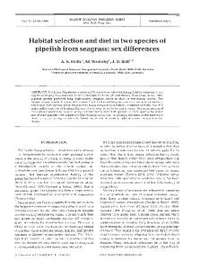
1. Introduction In the CHAMELEON/GECKO1 project a heterogeneous system-on-chip (SoC) for handheld multimedia devices is being designed [9]. It contains a general-purpose processor (i.e. an ARM core), a fine-grained reconfigurable part (consisting out of FPGA tiles) and a course-grained reconfigurable part. The latter comprises several MONTIUM processor tiles. The hardware organization within a tile is very regular and resembles a very long instruction word (VLIW) architecture. The five identical arithmetic and logic units (ALU1· · · ALU5) in a tile can exploit spatial concurrency to enhance performance. An ALU has two 16bit outputs, which are connected to the interconnect. The ALU is entirely combinatorial and consequentially there are no pipeline registers within the ALU. The diagram of the MONTIUM ALU in Fig. 1 identifies two different levels in the ALU. 1 This research is supported by PROGram for Research on Embedded Systems & Software (PROGRESS) of the Dutch organization for Scientific Research NWO, the Dutch Ministry of Economic Affaires and the technology foundation STW.
Proceedings of The 3rd IEEE International Workshop on System-on-Chip for Real-Time Applications ISBN 0-7695-1929-6/03 $17.00 © 2003 IEEE
Fig. 1. MONTIUM ALU The availability of high-level design entry tooling is critical for the viability of any reconfigurable architecture. A C compiler for the MONTIUM architecture is currently being implemented. In our toolset the input language C is first translated into a Control Data Flow Graph (CDFG). Next, the primitive operations are partitioned into clusters, such that each cluster can be executed by an MONTIUMtile within one clock cycle. After applying graph clustering, scheduling and allocation transformations on this minimized graph, the configurations for the MONTIUM can be generated. In this paper, we focus on the template generation algorithm. By analyzing the control data flow graphs, our algorithm can indicate which clusters of operations are the most frequently used. This information will guide compilers in selecting suitable configurations. Although, our primary target architecture is the MONTIUM processor, we believe that this technique can also be used for designing logic circuits or field programmable gate arrays (FPGA).
2. Related work There have been published many related research efforts in the areas of high-level synthesis and FPGA logic synthesis.
In [3][5], a template library is assumed to be available and the template matching is the focus of their work. [1][7] give some methods to generate templates. The drawback of [1][7] is that the generated templates are highly dependent on the choice of the initial template. The heuristic algorithm in [6] generates and maps templates simultaneously, but cannot avoid ill-fated decisions. The algorithms in [2][4] provide all templates of a CDFG. The complete set of tree templates and single-PO (single principle output) templates are generated in [4] and all the single-sink templates are found by the configuration profiling tool in [2]. In this paper, we will present an algorithm that can find the complete set of templates with multiple outputs.
3. Definitions on CDFGs
e1 e2 4
e3
e5 3
5
e6
u + e7
e8 1
e4
+ y
x +
w + e10
e9
+ v
2
e11
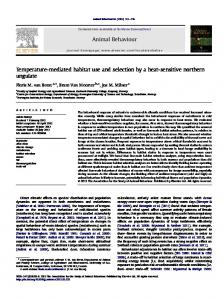
Fig. 2. A small CDFG A hydragraph G = (NG , PG , AG ) consists of two finite non-empty sets of nodes NG and ports PG and a set AG of so-called hydra-arcs; a hydra-arc a = (ta , Ha ) has one tail ta ∈ NG ∪ PG and a non-empty set of heads Ha ⊂ NG ∪ PG . In our applications, NG represents the operations of a CDFG, PG represents the inputs and outputs of the CDFG, while the hydra-arc (ta , Ha ) either reflects that an input is used by an operation (if ta ∈ PG ), or that an output of the operation represented by ta ∈ NG is input of the operations represented by Ha , or that this output is just an output of the CDFG (if Ha contains a port of PG ). See the example in Fig. 2: The operation of each node is a basic computation such as addition (in this case), multiplication, or subtraction. Hydra-arcs are directed from their tail to their heads. Because an operand might be input for more than one operation, a hydra-arc is allowed to have multiple heads although it always has only one tail. The hydra-arc e7 in Fig. 2, for instance, has two heads, w and v. The CDFG communicates with external systems through its ports represented by small grey circles in Fig. 2. Two distinct nodes u and v from NG are called neighbors if there exists a hydra-arc (t, H) with {u, v} ⊂ H ∪ {t}. These nodes are called connected within a hydragraph G if there exists a sequence u0 , . . . , uk of nodes from
Proceedings of The 3rd IEEE International Workshop on System-on-Chip for Real-Time Applications ISBN 0-7695-1929-6/03 $17.00 © 2003 IEEE
NG such that u0 = u, uk = v, and ui and ui+1 are neighbors for all i ∈ {0, . . . , k − 1}. If u and v are connected within G, then the smallest k for which such a sequence exists is called the distance of u and v within the hydragraph G, denoted by Dis(u, v|G); the distance is 0 if u = v. We call u and v are connected within a subset S ⊂ NG , if there exists a sequence u0 , . . . , uk of nodes from S such that u0 = u, uk = v, and ui and ui+1 are neighbors for all i ∈ {0, . . . , k − 1}. Correspondingly, the distance within a subset S is defined, denoted by Dis(u, v|S). A subset S of the nodes of a hydragraph is called connected if all pairs of distinct elements from S are connected within S. A hydragraph is called connected if all pairs of distinct elements from NG are connected within G, i.e., if NG is a connected set. Let S ⊂ NG be a non-empty connected set of nodes of the hydragraph G. Then S generates a connected hydragraph in the following natural way: For every v ∈ S consider the following two types of hydra-arcs of G related to v: • (tv , Hv ), so hydra-arcs with tail v: if Hv �⊂ S, we introduce a new port pv and replace (tv , Hv ) by (tv , (Hv ∩ S) ∪ {pv }); otherwise, we keep (tv , Hv ) as it is. • (tu , Hu ) with v ∈ Hu , so hydra-arcs for which v is one of the heads: if tu �∈ S, we introduce a new port t�u and replace (tu , Hu ) by (t�u , Hu ∩ S); otherwise we keep (tu , Hu ) as it is. Doing so for all hydra-arcs, e.g. starting from the sources in S, we obtain a unique hydragraph which we will refer to as the template generated by S in G. We denote it by TG [S] and say that S is a match of the template TG [S]. In the sequel we will only consider connected templates without always stating this explicitly. Templates (matches) with i nodes are called i-templates (i-matches). Correspondingly, a node subset S with i nodes are called i-node subset. A template will be mapped onto one MONTIUM ALU and executed within one clock cycle. The ports of a template represent intermediates that need to be stored for a while during the execution. For example, in Fig. 3 we see two templates of the CDFG from Fig. 2: the left one is generated by the set {x}, the right one by {v, w}. Compared with the original CDFG from Fig. 2, in the left one, the newly added port is a head for hydra-arc e5, while in the right one the newly added port is a tail for hydra-arc e7.
4. A template generation algorithm Given a CDFG G, the objective of the template generation algorithm is to find all the i templates with 1 ≤ i ≤maxsize and their corresponding matches from G. The
TG[{x}]
e1
x
e2
+
TG[{w,v}] e7
e8
w +
e9
+ v
e5 e10
e11
Tab. 1. Multiple copies of a match are filtered out. 1-matches {x} {y} {u}
Fig. 3. Two templates of the CDFG from Fig. 2
{u,y}
templates generation procedure is: 1 Starting with the 1-node subsets, generate a set of connected i-node subsets by adding a neighbor node to the (i − 1)-node subsets. 2 For all i-node subsets, consider their generated itemplates. Choose the set of nonisomorphic itemplates and list all matches of each of them. Templates that cannot be executed by one MONTIUM ALU within one clock cycle are discarded.
2-matches {x,u} 1 {y,u} 1 {u,w} 1 {u,v} 1 {u,x}
{v}
{v,u}
• Each hydragraph node is given a unique serial number (see the numbers enclosed in small boxes in Fig. 2). • A leading node is defined within each node subset S, which is the one with the smallest serial number. • Within a subset S, each graph node n ∈ S is given a circle number, denoted by Cir(n|S), which is the distance between the leading node and n within S, i.e., Cir(n|S)=Dis(S.LeadingNode, n|S). If a (i − 1)-node subset S and one of its neighbor node Nei satisfy the following conditions, S � = S∩ {Nei} will be considered as a i-node subset, otherwise S � is thrown away. 1 2 3
S.LeadingNode.Serial