TEMPORAL PARTITIONING AND SEQUENCING OF DATAFLOW GRAPHS ON RECONFIGURABLE SYSTEMS Christophe Bobda Heinz Nixdorf InstituteiPaderbom University Fuerstenallee II, D-33J02 Paderbom, Gennany
[email protected]
Abstract
FPGAs(Fie1d Programmable Gate Arrays) are often used as reconfigurable device. Because the functions to be implemented in FPGAs are often too big to fit in one device, they are divided into several partitions or configurations which can fit in the device. According to dependencies given in the function a Schedule is calculated. The partitions are successively downloaded in the device in accordance with the schedule until the complete function is computed. Often the time needed for reconfiguration is too high compared to the computation time [1. 11]. This paper presents a novel method for the reduction of the total reconfiguration time of a function by the generation of a minimal number of configurations. We present the framework that we developed for the fast and easy generation of configurations from a function modeled as DFG (dataflow graph).
Keywords:
Reconfigurable Computing. Temporal Partitioning. Fast Synthesis
1.
INTRODUCTION
Combining the dataflow aspect and the inherent parallelism which characterizes some classes of functions, FPGAs can be used to implement those functions more efficiently than CPUs and more flexible than ASICs. FPGAs have successfully been used to provide fast computation in many application areas including text and image processing and floating point computation. Reconfiguration is used to implement functions of any size in FPGAs with small capacity. This is done by dividing the functions in partitions which fits in the FPGAs. The partitions are implemented as configurations or bitstreams which are successively downloaded into FPGAs to compute the desire functions. This process is usually called temporal partitioning or temporal placement. Most of the works done on temporal partitioning assume the FPGAs to be either partially reconfigurable or time multiplexed. That means many configurations The original version of this chapter was revised: The copyright line was incorrect. This has been corrected. The Erratum to this chapter is available at DOI: 10.1007/978-0-387-35599-3_29
B. Kleinjohann et al. (eds.), Design and Analysis of Distributed Embedded Systems © IFIP International Federation for Information Processing 2002
186
Christophe Bobda
are stored on the chip and can be quickly (in nano seconds) downloaded in the FPGAs when needed. But the reality is different. Most of commercials FPGAs are neither time multiplexed nor really partial reconfigurable. For this purpose, many solutions proposed are not easily applicable. In practice high level tools are used to capture and solve problems which are geometrically based. The consequence is an inefficient use of the FPGA capabilities like the regularity structure. This paper examines the use of non-partial reconfigurable FPGAs to implement large functions. The goal is to minimize the reconfiguration overhead which is always too high compare to the computation time of function in FPGAs. We have developed a framework for the capture, the temporal partitioning and the generation of configurations from a given function in form of a DFG. Our framework is based on the JBits[6] API. We reduce the temporal placement problem to the placement of a small amount of modules in different configurations by dealing with cores. The rest of the paper is organized as follows: Section 2 presents the main work which has been carried in the temporal placement and temporal partitioning. In section 3 the formulation of the temporal placement problem based on the definitions already given in [12, 14] is given. The realization of overlapping between cores is shown in section 4. Section 5 presents the list scheduling based temporal partitioning method. To illustrate the concept of section 5, the partitioning method is applied on a real life problem in section 8. Section 9 concludes the paper and gives some directions for future work.
2.
RELATED WORK
The most used and perhaps the simplest approach to solve the temporal partitioning problem is the (enhance)list scheduling [11,3, 10,4, 13]. This method first places all the nodes of a DFG representing the problem to be solved in a list. Partitions(configurations) are built stepwise by removing nodes without predecessor in the list and allocate them to a partition until the size of the partition reached a limit(the size of the FPGA). Integer linear programming(ILP) [10, 5, 8] can be applied to solve some optimization constrains like timing. Other methods like network flow [9] and genetic algorithm [15] are also applied to find temporal partitions and optimize parameters like communication cost and configuration latency. In order to reduce the reconfiguration overhead, Pandey et al[ 11] suggested the reduction of number of partitions with resource sharing. For a new partition, a minimal resource set is chosen and a partition is built upon this resource set. Trimberger[13] proposed a time multiplexed FPGA architecture in which configurations can be stored directly on the chip. Reconfiguration is done in micro cycle. In a micro cycle a new configuration is downloaded from the on-chip memory. The CLBs(configurable logic block) contain micro-registers
Temporal Partitioning and Sequencing of Dataflow Graphs on RS
187
to temporally hold results of previous computation step when switching from one configuration to another. The geometrical view of the partial reconfiguration is considered in some extent in [12, 14]. The space and temporal placement of computational nodes of a DFG representing the problem to be computed in the FPGA is mapped, for example, to a packing problem[12]. Problems with high reconfiguration time(which are the focus of this paper) have been defined as a matter of future work. In practice high level description languages and tools are used to specify and solve a problem with important geometrical aspects. This leads to a non efficient use of the regularity structure of FPGAs[2] as well as waste of resource. We present an approach for the minimization of reconfiguration. For the Xilinx Virtex FPGA family that we use as RPU(reconfigurable processing unit), cores can be generated in the JBits environment. This java-based interface provides some basic functions like adders, comparators, subtracters, multipliers, multiplexers which can directly be placed on different locations on the FPGA and routed together to build complex functions.
3.
PROBLEM FORMULATION
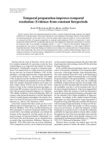
This section deals with definition and formulation of the problem to be solved. Since the definitions provided in [12, 14] are the most adapted for the temporal placement, we choose to adopt it and adjust them to fetch our considerations. Definition 1 (Dataflow Graph) GivenasetoftasksT = {Tt, .... , Td a dataflow graph is a directed acyclic graph G = (V, E), where V = T. An edge e = (Ti' Tj) E E is defined through the (data)dependence between task 11 and taskTj. Each node T in the DFG is equivalent to a core C which can be placed on the RPU H with length hx and width hy. Definition 2 (Temporal placement) Given a DFG G = (V, E) and a RPU H with the size (hx, hy), a temporal placement is a three dimensional vector junctionp = (Px,Py,Pt) : n N3, where the values Px(C), Py(C) denote the coordinates of the lower left position of the core C associate to a task T E V on the RPU. The core C occupied the space [Px(C), .. ,Px(C) +wx(C)] in the x direction, [Py (C), .. , Py (C) + Wy (C) 1in the y direction and [Pt (T), .. , Pt (T) + Wt (C)] in the time dimension. Figure 1 illustrate a temporal placement of a problem graph with three cores(+),(*) and (> ) representing tasks Tl , T2 and T3 ) with dependencies (Tl T 2 ) and (Tl T3) on a partial reconfigurable FPGA. In our formulation of the temporal partitioning, modules are allowed to overlap in space and time. Reconfiguration happens in today's FPGAs by the complete replacement of configuration, a process which is too costly compare to the
188
Christophe Bobda connluratlon
sequence
n-Ih (Onn.
2nd (Onn.
1st Conn,
Figure 1.
A temporal Placement
computation time[ll, 1]. To avoid such overhead, we exploit the free resources of modules already selected to run in the FPGA in a time interval to implement the modules for other computation. This process require no additional overhead, because only free resource are use. In fig.2, all the modules could not be placed simultaneously on the device if overlapping was not allowed.
(a) A DFG
Figure 2.
4.
(b) Temporal Placement with overlapping
A DFG and the corresponding temporal placement with ressource sharing
IMPLEMENTATION OF OVERLAPPING CORES AND RESSOURCE SHARING
If two cores C1 and C2 share the same resource Co and if the free resource in core Co are enough to implement the functionality of Co, then Co can be shared by C1 and C2 without additional resource. For example, a Virtex register implemented in the JBits use only the Fl and G 1 inputs of the slice 0 or 1 of a
Temporal Partitioning and Sequencing of Dataflow Graphs on RS
189
ALGORITHM I: generate_partitions(DFG G, DEVICE dev) 1 BEGIN; 2 list-nodes := generate_nodes_lisL with_priority(G); 3 WHILE (lIist-node.emptyO) DO 4 aIlocated_list.resetO; 5 FOR(i:= 1; i < Iist_nodes.sizeO;i++) 6 chosen_node:= node_list[i); besLnode:= geLbest-overlapping_nodeO; 7 8 IF (best_node = NULL) 9 IF (allocated_list.size + chosen_node.size < dev.size) 10 aIlocated_list.insert( chosen_ node); 11 IisLnode.remove(chosen_node); 12 ELSE 13 implement_overlap(chosen_node, besLnode); 14 IisLpartition.insert(allocated_list); 15 END;
Figure 3.
The temporal partitioning algorithm
CLB(Configurable logic Block). Its outputs are the Xq and Yq outputs of the corresponding slice. The resource F2, .. , G4, F2, .. , G3 , cin, X, X B, YB as well as the remaining Xq and Yq are free in the two slices of the CLBs allocated to the register core. They can be used 0 implement another register in the same core. If the core Co has no additional resource, I/O Multiplexing is commonly used to allocate the common resource Co either to C1 or to C2 depending on a predefined schedule. For two inputs II and 12 and a condition C, I/O multiplexing is implemented as follow: If C = 1 then Z = II, else Z = h. This is equivalent to the boolean equation Z = C.l1 + notZ = C.12 which can easily be implemented in a 3-inputs LUT. As we can see in this example, sharing resource in FPGA without additional overhead is possible, since the cores provided in the JBits environment use only a fraction of the resource allocated to them.
5.
THE TEMPORAL PARTITIONING ALGORITHM
This section provides the description of our partitioning algorithm. The method generate_partitions (ALGORITHM I) is a list scheduling like method which takes as inputs a DFG G and a device type dev and return a list of all partitions lisLpartition. At the begin all the nodes of the DFG are inserted in lisLnodes in order of decreasing priority (line 2). In order to make a maximum use of overlapping capability, the priority is high in function of the non inclusion of the core in other cores, the non precedence by other cores in the list and the size of the core. At each step of the partitioning, a node chosen_node with maximum priority
190
Christophe Bobda
is removed from lisLnodes and inserted in allocatedJist(lines 6, 10 - 11, 14 - 16), which is the list of all elements of the current partition. It represents the resource running in the FPGA in a time interval. In order to make an efficient use of those resource for the next time interval, we first check for intersection between chosen_node and the nodes currently assigned to allocatedJist. The function get_besLoverlapping_node will return the node which has a maximum overlapping core with chosen_node. If no such node exists, chosen_node will be added to the current partition allocatedJist, if the resulting partition fits in the device (lines 7 - 11). In the case where a best overlapping node exists, the overlapping concept as shown in section 4(lines 12 - 13) will be implemented. The current partition allocatedJist is inserted in the list of all partitions when all the nodes in lisLnodes have been processed (line 14). If the list of nodes lisLnodes is not empty, a new partition is created and the processing continues (lines 3 - 14).
6.
PLACEMENT OF MODULES IN CONFIGURATIONS
Having the list of all partitions, we use an enhanced eigenvector based placement to arrange the cores of each partition on the surface of the device and the resource inside the merged cores. This method has the advantage of placing Inputs and Outputs (110) elements at the boundary of the cores and the device, which makes pipelining easier. The method is based on the two dimensional spectral embedding of the nodes of the DFG using eigenvectors. Having a spectral embedding of the nodes in the plane, a post-processing method is used to successively remove the nodes not in the actual partition and fit the rest in the device area. The computation of the positions of modules on the device surface happen as follow: Given a DFG G = (V, E) representing the modules and their interconnexion, the connection matrix, degree matrix and laplacian are first computed. • The connection matrix of G is the symetric matrix C (1 :5 i,j :51 V I) and Ci,j = 1 {::::::> (Vi, Vj) E E.
= (Ci,j)
with
• The degree matrix ofG is the diagonal matrix D = (di,j), (1 :5 i,j V I) with i .4, J' --t d·t,3. = 0 and d·t,I. = L.J3=1 '1,3' r, .
:51
• The laplacian matrix of G is the matrix B = D - C. In [7] Hall proved that the r eigenvectors of the laplacian matrix related to the r smallest non zero eigenvalues of B define the coordinates of the 1 V 1 modules of G in an r-dimensional vector space, such that the sum of the distances between the modules is minimal. We first compute the r smallest eigenvalues,
Temporal Partitioning and Sequencing of Dataflow Graphs on RS
191
then we use a post-processing step to generate the definitive position of each core in the corresponding bitstream. The algorithm described here is implemented in a framework that we developed.
7.
CONFIGURATION SEQUENCING
Given a DFG, our tool compute a configuration graph(figA) in which nodes represents configurations. Configurations communicate via inter configuration registers(figA), which are automatically inserted in bitstreams when an arc of the DFG connects two components in different configurations. The inter configuration registers are mapped in the CPU address room and are used for the communication between nodes in different configurations. The nodes of the configuration graph, that means the configurations are successively downloaded in the FPGA until the computation of the original DFG completes.
Inter Connguratlon
registers
Figure 4.
8.
A Configuration Graph
CASE STUDY: NUMERICAL SOLUTION OF A DIFFERENTIAL EQUATION
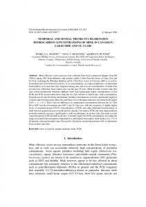
To illustrate and show the efficiency of the method described in this paper, a numerical method for solving a differential equation as described in [12] is considered. Fig 5 shows the DFG for solving a differential equation of the form Y" + 3xyl + 3y = 0 in the interval [xo l a] with step size dx and initial values y(xo) = Yo, yl(XO) = Uo, using Euler's method as presented in [12]. We consider the worst case, where no additional resource is left in the available cores to implement the core overlapping. I/O multiplexing have to be considered in this case. The size of the different modules for the Xilinx Virtex architecture is given in table 1. As we can see, the size of a 2 inputs 1 output 16 Bit-Multiplexer is less than (10 x 1). Since the size of a 16 Bit-multiplier is more than (5 x 20), merging two cores sharing a mUltiplier module will have a reduction of the
192
Christophe Bobda
% . ..,
Figure 5.
Table 1.
% ADDI.
M1IL.
o
M1ILI
-N....
O-c-
DFG For the DE-Integrator
Cores Size(in CLB) for the Xilinx Virtex Architecture Cores 16-Bit Add 16-Bit Sub 16-BitComp 2 In/I-Out 16-Bit Mux 16-Bit Mul
X..size 8 8 8 10
5
y..size 1 1 1 1 20
size of a multiplier (5 x 20) and an augmentation of 3 times the size of a multiplexer(3 x (9 xl) on the size of the resulting core. The net gain we have is about 70 CLBs. With this observation the method described in 5 is suited to implement the DFG in a Virtex device. When targeting any of the Virtex above the Virtex 300 with a minimum area of (32 x 48), the design will completely fit in it. Only one partition will be generated and reconfiguration is not needed. When targeting the Virtex 100 with size (20 x 30), the device can not hold more than 4 multipliers simultaneously. Another temporal partitioning algorithm will produce a minimum of two partitions in order to implement the DFG. For 1000 iterations of the DFG computations, the device will be configured 1000 times. With a reconfiguration time of 28 the time needed only for reconfiguration will be 20008. This solution is not applicable. The algorithm provided in this paper will generate only one partition for the same device. This means the reconfiguration time is reduced to zero. The device will contain 3 multipliers, 2 substracters one adder one comparator and 9 multiplexers in the worst case. The total number of CLBs needed is 464. The design easily fits in the target device (Virtex 100). Table 2 gives an overview over the sharing of modules among cores in the device.
Temporal Partitioning and Sequencing of Dataflow Graphs on RS Table 2.
Resource sharing for the problem of section 8 (1)
Addl Subl Sub2 Compl Mull Mul2 Mul3
9.
193
-
-
X
-
(2)
-
-
X
(3)
-
X
(4)
-
X
-
(5) X
(6)
(7)
- - X - - X X - - X - - X - - -
CONCLUSION
This paper has presented a novel approach for the temporal placement of DFG on a reconfigurable platform. The paper shows that allowing overlapping of cores in the space and time can lead to a reduction in the number of partitions. Sharing modules in FPGAs and switching from one core to another can increase the latency of the partitions. Because the latency of a bitstream varies from nanoseconds to microseconds, while the reconfiguration time of an FPGA is more than a second, the overall performance of functions depends more on the reconfiguration time than the computation time.
References [1] C. Bobda and N. Steenbock. Singular value decomposition on distributed reconfigurable systems. In 12th IEEE International Workshop On Rapid System Prototyping(RSP'OI), Monterey California. IEEE Computer Society, 2001. [2] T. 1. Callahan, P. Chong, A. Dehon, and 1. Wawrzynek. Fast module mapping and placement for datapaths in fpgas. In International Symposium on Field Programmable Gate Arrays(FPGA 98), pages 123 -132, Monterey, California, 1998. ACMlSIGDA. [3] 1. M. P. Cardoso and H. C. Neto. An enhance static-list scheduling algorithm for temporal partitioning onto rpus. In IFlP TC/o WG/O.5 /0 Int. Conf. on Very Large Scale Integration(VLSI'99), pages 485 -496, Lisboa, Portugal, 1999. IFIP. [4] D. Chang and M. Marek-Sadowska. Partitioning sequential circuits on dynamicaly reconfigurable fpgas. In International Symposium on Field Programmable Gate Arrays(FPGA 98), pages 161-167, Monterey, California, 1998. ACMlSIGDA. [5] Ejnioui and N. Ranganathan. Circuit scheduling on time-multiplexed fpgas. [6] S. Guccione, D. Levi, and P. Sundararajan. Jbits: A java-based interface for reconfigurable computing, 1999. [7] K. Hall. dimensional quadratic placement algorithm, 1970. [8J M. Kaul, R. Vemuri, S. Govindarajan, and I. Ouaiss. An automated temporal partitioning tool for a class of dsp applications, 1998.
194
Christophe Bobda
[9] H. Liu and D. F. Wong. Circuit partitioning for dynamicaly reconfigurable fpgas. In International Symposium on Field Programmable Gate Arrays(FPGA 98), pages 187194, Monterey, California, 1999. ACMlSIGDA. [10] I. Ouaiss, S. Govindarajan, V. Srinivasan, M. Kaul, and R. Vemuri. An integrated partitioning and synthesis system for dynamically reconfigurable multi-FPGA architectures. In IPPs/sPDP Workshops, pages 31-36, 1998. [11] A. Pandey and R. Vemuri. Combined temporal partitioning and scheduling for reconfigurable architectures. In 1. Schewel, P. M. Athanas, S. A. Guccione, S. Ludwig, and 1. T. McHenry, editors, Reconfigurable Technology: FPGAs for Computing and Applications, Proc. SPIE 3844, pages 93-103, Bellingham, WA, 1999. SPIE - The International Society for Optical Engineering. [12] 1. Teich, S. P. Fekete, and 1. Schepers. Optimizing dynamic hardware reconfiguration. Technical Report 97.228, Angewante Mathematic Und Informatik Universitat zu Koln, 1998. [13] S. Trimberger. Circuit partitioning for dynamicaly reconfigurable fpgas. In International Symposium on Field Programmable Gate Arrays(FPGA 98), pages 153 - 160, Monterey, California, 1999. ACMlSIGDA. [14] M. Vasilko. Dynasty: A temporal floorplanning based cad framework for dynamicaly reconfigurable logic systems. In P. Lysaght and J. Irvine, editors, Field Programmable Logic and Aplications FPL 1999, pages 124-133, Glasgow, UK, 1999. Springer. [15] M. Vasilko and G. Benyon-Tinker. Automatic temporal floorplanning with guaranteed solution feasibility. In R. Hartenstein and H. GrUnbacher, editors, Field Programmable Logic and Aplications FPL 2000, pages ViUach, Austria, 2000. Springer.