1
Terahertz superlattice parametric oscillator K. F. Renk*, B. I. Stahl, A. Rogl, and T. Janzen Institut für Angewandte Physik, Universität Regensburg, 93040 Regensburg, Germany D. G. Pavel’ev and Yu. I. Koshurinov Department of Radiophysics, Nizhny Novgorod State University, Nizhny Novgorod, Russia V. Ustinov and A. Zhukov A.F. Ioffe Physico-Technical Institute, St. Petersburg, Russia
We report a GaAs/AlAs superlattice parametric oscillator. It was pumped by a microwave field (power few mW) and produced 3rd harmonic radiation (frequency near 300 GHz). The nonlinearity of the active superlattice was due to Bragg reflections of conduction electrons at the superlattice planes. A theory of the nonlinearity indicates that parametric oscillation should be possible up to frequencies above 10 THz. The active superlattice may be the object of further studies of predicted extraordinary nonlinearities for THz fields.
*
[email protected]
A semiconductor superlattice can show a negative differential resistance due to Bragg reflections of the conduction electrons at the superlattice planes [1, 2]. And a superlattice in a negative-differential resistance state can be a gain medium for highfrequency radiation as predicted [3] and concluded from a voltage-induced anomalous THz transmissivity of an array of superlattices [4]. An oscillator with a voltage-biased superlattice as the active element is a candidate for a roomtemperature, coherent radiation source in the THz frequency range (see, e.g. Refs. 4 and 5); at present the quantum cascade laser (frequency near 4 THz), operated at liquid nitrogen temperature, is a first compact coherent THz radiation source [6]. In this Letter, we show, experimentally and theoretically, that the nonlinearity mediated
2
by Bragg reflections of the conduction electrons in a superlattice can be used to operate a parametric oscillator suitable for generation of sub-THz and, possibly, THz radiation.
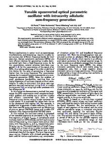
Fig. 1. (a) Principle of the semiconductor superlattice parametric oscillator with a superlattice (SL)-active medium. (b) Superlattice parametric oscillator (SPO) and detector (mixer). (c) Superlattice in a quasiplanar design. (d) Experimental current-voltage curve, measured with a static voltage source. . The superlattice parametric oscillator (Fig. 1a) is pumped by a microwave field (pump frequency ω1 ) and generates 3rd harmonic radiation (frequency ω3 ). A resonator (reflector r1, partial reflector r2) for the 3rd harmonic radiation delivers feedback necessary for the initiation and maintenance of parametric oscillation [7, 8]. The superlattice, mounted in a waveguide structure (Fig. 1b), was coupled to a 3rd harmonic-waveguide resonator having a fixed backshort (r1) and with r2 being formed by a mismatch between output port and horn, and to a pump waveguide. Radiation was detected with a thermal detector (Golay cell or powermeter) or a frequency mixer connected to a spectrum analyzer. A 3rd harmonic signal and a pump radiation-leakage signal were measures for the corresponding fields at the site of the superlattice. For pumping we used radiation of a frequency synthesizer (power 4
3
mW). In a quasiplanar design (Fig. 2c), the superlattice (diameter ~ 1.5 µm; length 0.1 µm; doping 1018 cm-3) was connected to an antenna and, via an n+ GaAs layer and a large-size superlattice (of low resistance) to another antenna. The current-voltage curve (Fig. 2d) showed, above a critical voltage Uc (~ 0.2 V), a negative resistance together with current jumps due to the formation of space-charge domains [9]. The system (Figs. 1b, c, d) has been described in detail elsewhere as a frequency multiplier based on transient domains induced by the microwave pump field [10]. A first sign of parametric oscillation was a threshold behavior of the frequency
Fig. 2. (a) Frequency characteristics of the parametric oscillator. (b) Pump-leakage signal (S1) and 3rd harmonic signal (S3) for different levels of the pump power P1. (c) Domain-mediated frequency multiplication versus parametric oscillation.
4
characteristic of the 3rd harmonic signal S3 (Fig. 2a). At a threshold pump power (Pth), the oscillation range was narrow. With increasing pump power (P1), the frequency characteristic broadened and extended at large P1 over a range of about 0.3 percent of the centre frequency. Both S3 and the pump-leakage signal S1 , measured at the centre frequency, depended strongly on P1 (Fig. 2b). S3 increased, with increasing P1, nonlinearly at small P1 as expected for conventional frequency tripling, showed an abrupt increase at Pth and saturated at larger P1. We attribute Pth to the threshold of parametric oscillation [11]. The pump-leakage signal S1 increased linearly with P1 up to a critical power (Pc) where a strong increase occurred, followed by a weaker increase. We associate Pc with the onset of a negative differential resistance and the corresponding amplitude Uˆ1 of the pump field with the critical voltage ( Uˆ1 ~ Uc). The strong increase of S1 above Pc indicated an improvement of the matching of the superlattice to the pump waveguide. Within the pump power range from Pc to a power level (slightly above Pth) which corresponded to the onset of saturation of S3, the signal S1 increased strongly (by a factor of ~ 12) indicating that the amplitude of the pump voltage across the superlattice increased strongly (from Uˆ1 ~ Uc to ~ 3.5 Uc). We found that a decrease of the reflectivity of the partial reflector (r2) resulted in an increase of Pth (up to 10 %) which revealed the occurrence of feedback; strong feedback effects occurred also when we coupled the waveguide resonator to an external resonator for the 3rd harmonic field. The oscillator delivered, at optimum output coupling, a power of about 0.1 mW. We also observed (Fig. 2c) domain-mediated frequency multiplication, distinguished by continuous tuneability over a very wide frequency range, and by its insensibility against feedback by a resonator, and by not having a sharp pump threshold. A simulation of the domain-mediated frequency multiplication showed that the conversion efficiency was also about 10 percent, in agreement with the experimental result. The saturated signal (Fig. 2c) decreased (in the average) slightly towards the higher frequencies and extended up to a frequency (285 GHz; ω3 τ ~ 0.3 where τ is an average relaxation time of our superlattice at room temperature) where parametric oscillation took over; a structure in the frequency characteristic of the parametric
5
oscillation range can be attributed to coupling of the 3rd harmonic field to the pump waveguide.
Fig. 3. (a) Esaki-Tsu current voltage curve. (b) Voltages and currents involved in the parametric oscillation. We attribute the parametric oscillation to single-electron dynamics. For an (Uc) and a illustration of the gain mechanism, we regard the Esaki-Tsu current-voltage curve [1] (Fig. 3a). The curve is nonlinear, it shows a current peak (Ip) at the critical voltage negative differential resistance above Uc. The mechanism of parametric gain is sketched in Fig. 1b. A microwave pump voltage (U1) of an amplitude larger than Uc and a 3rd harmonic voltage (U3) add to a total voltage (U1 + U3). For an instantaneous voltage U = Uˆ1 cos(ω1t ) + Uˆ 3 cos(ω3 t ) across the superlattice, optimum gain is expected for the amplitudes Uˆ1 ~ 3 U c and Uˆ 3 ~ U c . Then, (U1 + U3) is almost zero for a noticeable time and changes rapidly to values above Uc, i.e. the superlattice is switched fast between transient states of positive and negative differential resistance.
6
The current (I) contains a 3rd harmonic current (I3) of opposite phase relative to U3, i.e. the product U3I3 is negative, indicating gain for the 3rd harmonic. For a theoretical analysis we use the dispersion relation ε = 12 ∆(1 − cos(ka )) where ε is the energy and k the wave vector for the motion along the superlattice axis, a is the superlattice period, and ∆ the width of a miniband formed according to the superlattice periodicity. A Boltzmann transport equation leads to the time dependent drift velocity [12] ⎡ t ea ⎤ dt 0 ⎛ t − t0 ⎞ exp ⎜ − E( t 1 ) dt1 ⎥ ⎟ ⋅ sin ⎢− ∫ τ ⎠ ⎝ ⎢⎣ t 0 h ⎥⎦ −∞ τ t
v( t ) = 2v p ∫
where E(t) = U(t)/L is the instantaneous field strength, v p =
1 ∆a I ( x ) / I ( x ) 1 0 4h
(1)
is the
peak drift velocity, I1 and I 0 are the first and zeroth order Bessel functions and x = ∆ /(2k B T) , and L the superlattice length (T temperature, h Planck’s constant, e
elementary charge, kB Boltzmann constant). The sine term in eq. (1) describes the Bragg reflections [13] and the exponential term the electron relaxation; the different time scales (t1, t0, t) take into account that the relaxation is a statistical process. By Fourier analysis, we determined the amplitudes of the drift velocities vˆ i (i = 1 or 3) and of the current ( ˆI i / I p = vˆ i / v p ) using for Ip the experimental value and we calculated the power P3 =
1 ˆI U ˆ 2 3 3
as well as the resistance R3 = Uˆ 3 / ˆI 3 for the 3rd
harmonic field. Results for Uˆ1 = 3U c are shown in Fig. 4a. We find a region of gain (P3 < 0, R3 < 0) on the Uˆ 3 scale, separated by a point of zero conductance (R3-1 = 0) from a range of loss. Optimum gain is found for Uˆ1 = Uc, i.e. for the Bragg-reflection frequency, ˆ / L , being equal to the relaxation rate (ω ˆ B = 1 eaU ω ˆ B = τ −1 ) . In the range of optimum 3 h
gain, P3 varies only slightly while |R3| shows a strong increase due to the singularity. Accordingly, the active superlattice has the ability to match itself to the 3rd harmonic resonator, via the R3( Uˆ 3 ) dependence and, additionally, to the pump waveguide via the R1( Uˆ1 ) dependence; the waveguide impedances were between 100 Ω and 200 Ω .
7
It follows for the case of optimal gain ( Uˆ1 = 3U c ; Uˆ 3 = U c ) that the power conversion efficiency (~ 0.1) for conversion of pump to 3rd harmonic power is almost independent of Uc and Ip [14]. The calculated 3rd harmonic power is in accordance with the experiment if 3rd harmonic-radiation losses to the pump waveguide and to the superlattice-series
Fig. 4. (a) Power P3 and resistance R3 of the 3rd harmonic field for different amplitudes of the 3rd harmonic field. (b) 3rd harmonic power P3 for different frequencies. (c) Maximum oscillation frequency ω3m for different pump-voltage amplitudes ( Uˆ1 ). resistance are taken into account. A power balance shows that a 3rd harmonic photon made in the average about three passages through the active superlattice, delivering the gain coefficient (3⋅104 cm-1) and the gain-cross section (3⋅10-14 cm2) for an electron, in accordance with the calculated spatial amplitude (~ 1 nm) of the drift oscillation of an electron at the frequency ω3 . The frequency dependence (Fig. 4b) indicates that |P3| decreases, in the range of gain, with increasing ω3 up to a
8
maximum frequency ω3m / 2π (~ 1 THz). The maximum frequency (Fig. 4c) can be raised to the THz range if besides the pump frequency also the pump-voltage amplitude is increased; ∆ has to be appropriately chosen to fulfil the condition hω3 < ∆ . Parametric oscillators of higher power in series or, alternatively, a
parametric oscillator working on a higher than the 3rd harmonic, should allow reaching, with a conventional microwave pump source, the THz range. Domain-mediated tripling has a frequency cut-off near 1 THz (where ω3 τ ~ 1 [15]). Our experiment indicates that, for a microwave-pumped superlattice, a transientdomain state can be overcome already in the sub-THz range ( ω3 τ ~ 0.3 ) by the singleelectron nonequilibrium gain state [16, 17]. In conclusion, we demonstrated the operation of a parametric oscillator with a superlattice as the active medium having a high gain that is based on Bragg reflections of the conduction electrons, and presented a theoretical analysis suggesting that a superlattice parametric oscillator should be achievable at THz frequencies. We also showed that under appropriate experimental conditions a domain state can be avoided in favour of a single-electron nonequilibrium state, which can be the basis for further experimental studies of this state with extraordinary nonlinear properties at sub-THz and THz frequencies. Due to attractive properties, namely narrow bandwidth, coherence, compactness, room-temperature operation, and the wide tuneability, the superlattice parametric oscillator appears to be a promising optoelectronic device.
Acknowledgement The experimental realization of the parametric oscillation was first recognized by K.F.R. Experiment and theory were performed in Regensburg, construction of the frequency multiplier and superlattice structuring as well as a simulation of the domain-mediated frequency multiplication in Nizhny Novgorod, and the preparation of the superlattice in Sankt Petersburg. One of us (K.F.R.) would like to thank L. Keldysh for fruitful discussions. The work has been supported by the Deutsche Forschungsgemeinschaft and the Russian Foundation for Basic Research.
9
References [1]
L. Esaki and R. Tsu, IBM J. Res. Develop. 14, 61 (1970).
[2]
A. Sibille, J. F. Palmier, H. Wang, and F. Mollot, Phys. Rev. Lett. 64, 52 (1990).
[3]
S.A. Ktitorov, G.S. Simin, and V.Ya. Sindalovskii, Fiz. Tverd. Tela 13, 2230 (1971) [Sov., Phys. Solid State 13, 1872 (1972)].
[4]
P.G. Savvidis, B. Kolasa, G. Lee, and S.J. Allen, Phys. Rev. Lett. 92, 196802 (2004).
[5]
E. Schomburg, N.V. Demarina, and K.F. Renk, Phys. Rev. B 67, 155302 (2003).
[6]
R. Köhler et al., Nature 417, 156 (2002); L. Mahler et al., App. Phys. Lett. 84, 5446 (2004).
[7]
An idea of a microwave pumped superlattice oscillator has been published earlier; F. Klappenberger and K.F. Renk, Intern. Journ. Infrared and Millimeter Waves 25, 429 (2004).
[8]
K. Alekseev, reading our preliminary manuscript, informed us about earlier work on parametric interaction; V.V. Pavlovich, Fiz. Tverd. Tela 19, 97 (1977) [Sov. Phys. Solid State 19, 54 (1977)], predicted the amplification of a weak high-frequency field in a superlattice submitted to a strong pump field; Yu.A. Romanov, Izv. Vyssh. Uchebn. Zaved. Radiofiz. 23, 617 (1980) [Radiophys. and Quantum Electr. 23, 421 (1980) (Consultant’s Bureau N.Y.)], considered parametric generation of uneven harmonics in a superlattice under the condition of a strong nonlinearity.
[9]
H. Kroemer, Proc. IEEE 58, 1844 (1970); M. Büttiker and H. Thomas, Phys. Rev. Lett. 38, 78 (1977); A.A. Ignatov, V.I. Piskarev, and V.I. Shashkin, Sov. Phys. Semicond. 19, 1345 (1985); K. Hofbeck et al., Phys. Lett. A 218, 349 (1996); for a discussion of domains see also Ref. 4.
[10] F. Klappenberger, K.F. Renk, P. Renk, B. Rieder, Yu. I. Koschurinov, D.G. Pavel’ev, V. Ustinov, A. Zhukov, N. Maleev, and A. Vasilyev, Appl. Phys. Lett. 84, 3924 (2004).
10
[11] In Ref. 10 similar results for S3 have been reported, however, the threshold was attributed to the onset of domain formation rather than to an oscillation threshold. [12] A.A.Ignatov, E. Schomburg, J. Grenzer, K. F. Renk, and E.P. Dodin, Z. Phys. B 98, 187 (1995); A.A. Ignatov and Yu.A.Romanov, Phys. Stat. Sol. B 73, 327 (1976); A.A. Ignatov, K.F. Renk, and E.P. Dodin, Phys. Rev. Lett. 70, 1996 (1993). [13] In a static field, the sine term describes Bloch oscillations; see, J. Feldmann et al., Phys. Rev. B 46, R7252(1992); F. Bloch, Z. Physik 52, 555 (1928); C. Zener, Proc. Roy. Soc. London Ser. A 145, 523 (1934). [14] The calculation delivers, for the optimal conditions and ω3 τ < 1 , the current amplitudes ˆI1 ~ 23 I p and ˆI3 ~ 13 I p , the resistances R1 ~ 4 Up/Ic and R3 ~ - 3 Up/Ic, the pump power P1 ~ UcIp and the 3rd harmonic power P3 ~ 19 U c I p . [15] F. Klappenberger et al., Eur. Phys. J. B 39, 483 (2004). [16] For other possibilities of domain suppression, see Ref. 4 and also V.I. Litvinov and A. Manasson, Phys. Rev. B 70, 195323 (2004) and references therein. [17] A domain-less superlattice is expected to show, besides THz-gain, further interesting effects due to the extraordinary nonlinearity, such as dynamic electron localization, self-induced transparency and chaotic behavior, see Yu. Romanov and Yu.Yu. Romanova, Phys. Solid State 46, 164 (2003) and Yu. A. Romanov, L.G. Mourokh, and J.M. Horing, J. Appl. Phys. 93, 9469 (2003).