a Department of Geology, Unit'ersity College Cork, Ireland ..... phytic vegetation often grows in or near river ...... observed near the Killarney-Mallow Fault in the.
Sedimentary Geology, 85 (1993)339-374
33~
Elsevier Science Publishers B.V., A m s t e r d a m
Terminal fans
a review with reference to Devonian examples S e a n B. K e l l y a a n d H e n r i k O l s e n b
a Department of Geology, Unit'ersity College Cork, Ireland h Department of Geology and Geotechnical Engineering, Danmarks Tekniske Hojskole Building 204, DK-2800 Lyngb~'. Denmark Received August 17, 1992: revised version accepted D e c e m b e r 1, 1992
ABSTRACT Kelly, S.B. and Olsen, H., 1993. Terminal f a n s - - a review with reference to Devonian examples. In: C.R. Fielding (Editor), Current Research in Fluvial Sedimentology. Sediment. Geol., 85: 339-374. Terminal fans occur where sediment-laden streams decrease in size and vanish as a result of evaporation and transmission losses. They tend to form in arid or semi-arid regions which are characterized by a moisture deficit. Distributary channel patterns are characteristic of terminal fans, and reflect both loss of stream power and spatially/temporally fluctuating discharge. In a n u m b e r of Devonian basins, terminal fan sediments form conspicuous sequences with examples from Spitsbergen, England, Ireland and Greenland. Examples of terminal fan systems from the Northeast Greenland Basin and the Munster Basin in Ireland are presented in this paper. The ancient examples are used in combination with modern distributary systems to construct a simple facies model for terminal fans and their deposits. The model includes a tripartite zonation of terminal fans into feeder, distributary and basinal zones. The feeder zone is characterized by large channel bodies associated with interchannel fines. An increase in channel body frequency may occur at the transition from the feeder zone to the distributary zone, reflecting the downstream multifurcation of channels. The distributary zone is characterized by a downstream decrease in both the scale and frequency of channel deposits, which are mainly replaced by sheetflood deposits. This is the result of the decline of both water depth and stream power downslope. Further evidence of terminal fan systems is the downstream transition from distal to basinal zone deposits of floodbasin, playa mudflat or aeolian origin, reflecting the absence of a terminal base level in the form of a lake or the sea.
Introduction Several ancient fluvial systems can be interpreted as terminal fans (Friend, 1978), and "as our understanding of 'terminal fan' systems increases it would seem there is as great a variability of facies models as is already well-perceived for meandering and braided stream systems" (Tunbridge, 1984, p. 713). The purpose of this
Correspondence to: Sean B. Kelly, G e o c h e m Group Limited, Unit 3, Commerce Centre Souter Head Road, Altens Industrial Estate, Aberdeen AB1 4LF, UK.
p a p e r is to review fluvial sand-dominated and mixed-load terminal fans, both ancient and modern, in terms of process and product. Initially, the processes characteristic of terminal fans and related systems are discussed and incorporated into a generalised environmental model. The applicability of this model is then illustrated with several examples of M i d d l e - U p per Devonian terminal fan systems from Greenland and Ireland. Finally, a general facies model is proposed which incorporates the observations from both modern and ancient systems. It is hoped that this model may serve as a framework for future studies of terminal fan systems.
0037-0738/93/$06.00 © 1993 - Elsevier Science Publishers B.V. All rights reserved
340
'-,,B.
KEI_I?YAN[) H ()LS.}'".
.....................
Terminal fans
The term terminal fan is used here to describe fluvial distributary systems in which the drainage is wholly dissipated internally via a distributary network from which no water escapes by surface flow to a take or the sea during normal conditions. There are notable differences between conventional coarse-grained alluvial fans (e.g. Heward, 1978) and the sand-dominated/mixed-load, lowgradient, terminal fan systems considered in this paper. Alluvial fans generally result from a marked drop in local base level, e.g. along mountain fronts, typically "where a heavily laden stream reaches the plain after flowing swiftly through a ravine or canyon" (Holmes, 1965). In contrast, the parent river of a terminal fan is generally mobile and not restricted to a ravine or canyon. Terminal fans develop primarily as a response to high evaporation/low precipitation rates (i.e. moisture deficit) and high infiltration rates. The only strictly terminal modern fans to have been described in any detail are the Markanda Fan (Mukerji, 1975, 1976; Parkash et al., 1983) and the Gash Fan (Abdullatif, 1989). Unfortunately, both of these have been modified by the cultivation of fan surfaces and the construction of irrigation channels and artificial levees (Parkash et al., 1983; Abdullatif, 1989), and this should be taken into account when using them as analogues for ancient terminal fan systems. Although the Gangetic Plains contain some of the best modern examples of terminal fan systems (Mukerji, 1975, 1976; Parkash et al., 1983; Friend in North et al., 1989), it has been demonstrated that many of the rivers which develop terminal fans are underfit streams occupying larger river valleys that formed during a wetter climatic phase (Mukerji, 1975; Singh, 1987; Singh et al., 1990). In addition, ancient systems often appear to have been much larger than these modern examples (Nichols, 1987). The Medano Creek, Colorado, is an example of a terminal fan which terminates in an aeolian sand sheet environment (Langford and Bracken, 1987; Langford, 1989). This system is rather lira-
~ - - - ~
-f
~
OR DISTRIB UTAF]IE.
'~.
20krrL .,',
"~
~'~ ~, " \,
-o
£
-, \,,
N
'~
DISTRIBUTAR" CHA~'~LS
~,,,, ql J ~r
\\\
FEEDER ~" . \
i
..2
\
\
\
i:,, I
{2 O c~ 77 oo
"2
4
SHEETFLOOO ~EPO~TS
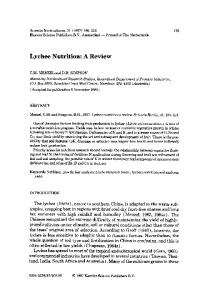
Fig. 1. Map of the terminal fan developed by the Rwer Gash. Sudan (after Abdultatif, 1989; pers. commun., 1992). The Gash Fan is an excellent example of a modern terminal fan system although it has been subjected to modification by human cultivation and irrigation. The feeder, distributa~' and basinal zones discussed in the text are indicated.
ited in lateral extent (the fan measures 1(1 km in length and 7 km in width). The Mojave River Wash, California, is another small terminal fan which terminates partly in aeolian sand sheets and dunes, and partly in playa mudflats (Langford, 1989). Aeolian environments can also form a significant component of larger terminal fan systems; for example, approximately 11% of the surface of the Gash Fan (Fig. 1) comprises aeolian sediments (O. Abdullatif. pers. commun.. 1992). Terminal fans can be subdivided into single entry systems (supplied from a point source) and
!
T E R M I N A L F A N S - - A R E V I E W WITH R E F E R E N C E T O D E V O N I A N E X A M P L E S
multiple entry systems. Only single entry systems have been described in detail from modern settings (e.g. Mukerji, 1975, 1976; Parkash et al., 1983; Abdullatif, 1989). Examples of modern multiple entry systems possibly include the wadi belts and piedmont alluvial plains described from north Africa (Glennie, 1970; G.E. Williams, 1970a). Processes
The two primary processes involved in the development of terminal fans are the break up of a stream into a network, and subsequent water loss through evaporation and infiltration. An understanding of these phenomena is critical in the assessment of such systems.
Channel diversion and bifurcation The cause and mechanism of diversion and bifurcation in terminal fans is frequently unclear, although the ultimate result is always to dissipate the energy of a system. Highly variable or seasonal discharge results in wide fluctuations in the amount of transported sediment load and can result in rapid deposition. Rapid aggradation may choke a channel midstream ("mid-channel overloading" of Leopold and Wolman, 1957) with the result that subsequent flow is divided around the obstruction. If channel threads do not rejoin then the channel may bifurcate (Parkash et al., 1980). Alternatively, diversion and bifurcation may occur via a process analogous to avulsion or crevasse splay development, with turbulence induced scour being concentrated at a particular point on a channel bank. This may result in breaching of the bank or levee and the establishment of a minor distributary channel (Mukerji, 1975). The angle of divergence, the inner angle between the parent and minor distributary measured in the downstream direction, is generally < 90 ° in most distributary systems. Mukerji (1975) observed in the Markanda fan that with increasing distance down-system, the angle of divergence decreases. Experimental data summarized by Garde and Ranga Raju (1978) suggest that as a consequence of the decreasing angles of diver-
341
gence, the proportion of diverted bedload may decrease down-system. Observations on natural channel bifurcations indicate that the diversion of bedload as well as the diversion of suspended load is mainly dependent on the relative transporting capacities of the parent and minor distributary channels (Axelsson, 1967). Mukerji (1975) also observed that the lengths of successive distributary channels increase progressively with increasing distance down-system. This may also be explained by a decrease in angles of channel divergence allowing the diversion of greater discharge volumes into the distributaries and thereby increasing their survival lengths. The effects of diversion on an alluvial stream are related to the hydraulic effects mentioned above and the erodibility of the bed. While a minor distributary channel will often draw a relatively large share of the bedload, the parent channel downstream of a bifurcation will carry relatively less bedload. This may lead to erosion in the parent channel downstream of the diversion, although sediment deficiency may be partially balanced by erosion of channel banks (Garde and Ranga Raju, 1978).
Ecaporation and transmission loss Downstream reduction in discharge is a characteristic feature of terminal fans and is largely due to the combined effects of infiltration and evaporation. Evaporation and evapotranspiration can be important causes of water loss in ephemeral streams, especially if vegetation colonizes ephemeral channel courses (Hellwig, 1973a, b). Data from streams in arid climates such as the Gila (Arizona) and the Swakop (South Africa) indicate evaporation losses of 20-30 m 3 ha 1 day -I from stream beds alone (Culler, 197(I; Hellwig, 1973b). Evaporation on the floodplain is also important and can lead to the local development of salt flats or "salinas". Infiltration into a channel perimeter is termed "transmission loss". Ephemeral streams dominate tropical to subtropical semi-arid and arid drainage networks and are characterized by downstream changes as they lose water to the
342
~ II K F I 1 ~
surrounding alluvium (Leopold and Miller, 1956; Schumm and Hadley, 1957; Schumm, 1961). Rates of transmission loss are mainly a function of the permeability of the channel perimeter (Simon and Richardson, 1966; FAO, 1981). Transmission losses cause flood peaks and total discharge values to decline in the downstream direction (Babcock and Cushing, 1941: Burkham, 1970). In addition, transmission losses recharge groundwater aquifers (Renard and Keppel, 1966), increase the suspended-load concentration (Leopold and Miller, 1956) and promote aggradation (Schumm and Hadley, 1957; Bull, 1991). The magnitude of transmission losses is influenced by the relationship between inflow volume and the cross-sectional form of the channel. Many ephemeral channels are characterized by rectangular cross-sections with high w i d t h / d e p t h ratios (Schumm, 1961) and consist of an inner "axial zone" of low flow bordered by an "outer zone" which is only active during floods (e.g. Abdultatif, 1989). This means that a small increase in depth during flooding will yield rapid increases in the wetted perimeter with a consequent increase in transmission loss. Transmission losses are often so great in arid and semi-arid zones that eventually most surface flows decline to zero (Graf, 1988). If primary drainage channels of arid and semi-arid zones do
k N t ? ~t. i ~1 S l , %
not terminate at lakes or the sea, they often braid into a complex of micro-channels and are lost (Twidale, 1972; Rust, 1981). It is unusual for the active reach of an ephemeral water-coursc tt, extend more than 100 km downstream of its poini of emergence onto an alluvial plain (FAO, 1981, p. 5). This distance may therefore represent a broad upper limit for the downstream extent ot terminal fan systems. Modern terminal fan systems
A simple model is presented li,~ .,,and dominated and mixed-load tcrminal fans, I'hc model utilizes a subdivision of systems into feeder. distributary and basinal zones. This is largely based on descriptions of modern lcrminat fan systems (e.g. Fig. l), but also incorporates aspects of closely related systems. Each zone is characterized by different discharge regimes (Table' 1!. Feeder zone
The feeder zone or "'inner" fan area is dominated by the main feeder channel(s) and associated interchannel areas (Fig. 1). Although a well developed channel network may exist wilhin the feeder zone, a main channel, carrying a discharge greater than any other channel, can often be identified. This is usually characterized by its
TABLE I Characteristic discharge regime and dominanl facies of each zonal subdivision used in the description ot terminal lan~ Dominant processes
Dominant facies association
eeedt'r Zone
Channel flow > or ~- interchannet (interchannel: sheetflood _+ lacustrine ._+ aeolian)
Single or multistorey channel sandstone/conglomeralc bodies, lt)'s m thick, l()0's m wide. Overbank m u d s t o n e s / ~ a n d s t o n e s ± aeolian sandstones
Distributary zone Proximal: streamflow >> sheetflood
Multistorey channel sandstone bodies,
Medial: streamflow > or -~ sheetflood + aeolian
up 100 m thick (individual storeys < 5 m), 100s m wide Channel sandstone bodies (single and multistoreyL
Distal: sheetflood > streamflow + aeolian
2~5 m thick (generally < 100 m wide) Sheetflood sandstones + floodplain siltstones, depositional units < 2 m thick, 10s to 100s m wide, + aeolian sandstones
Basinal zone Sheetflood _+ aeolian _+ chemical
Floodbasin siltstones + aeolian sandstones _+ playa mudstoncs and cvaporites
T E R M I N A L F A N S - - A R E V I E W WITH R E F E R E N C E T O D E V O N I A N E X A M P L E S
greater width rather than its depth (e.g. Abdullatif, 1989). Feeder channels generally occupy relatively long-lived courses and are often slightly (or even deeply) entrenched. The reoccupation of channels is also more probable in the feeder zones of systems (cf. Rachocki, 1981). The main channel may define the "dynamic axis" of a system (Rachocki, 1981). This axis may gradually migrate across a system or "fan" surface (cf. Kosi River, Gole and Chitale, 1966). Current directions from the main channel at any specific point in the feeder zone will generally show a limited spread (cf. Bluck, 1980). Although the primary channel(s) may be perennial, it is likely that they are subject to dramatic variations in discharge due to marked seasonal variations in precipitation. If sufficiently coarse sediment is available, gravel deposition may characterize the feeder zones. Such gravelly zones or "Bhabar" occur on the Gangetic Plain and extend for 8-24 km in a downstream (Geddes, 1960; Parkash et al., 1980). However, these relatively coarse-grained zones quickly pass downstream into regions dominated by finer-grained deposition, probably accompanied by a decrease in slope. Interchannel areas generally receive little coarse-grained sediment although lateral overbank flooding can produce sandy "splays" and deposit large amounts of mud/silt (Parkash et al., 1983). In mixed-load fluvial systems, interchannel sequences within feeder zones are generally dominated by mudstones and occasional sheetflood sandstones, possibly with local lake deposits. In sand-prone systems aeolian facies may dominate the interchannel environment (e.g. the Great Sand Dunes along the Medano Creek, Colorado, Langford, 1989). Distributary zone
Distributary zones are dominated by distributary channels which are the result of the downstream bifurcation of the main feeder channel(s). Interehannel areas are often limited in extent due to the active nature of the distributary channel courses. Distributary channels are commonly
343
ephemeral and often characterized by features such as low-stage braiding and bar emergence (Abdullatif, 1989). However, perennial, though fluctuating flow may occur in larger distributary channels (Mukerji, 1976). The characteristics of ephemeral distributary channels, particularly channel width, fluctuate spatially and temporally in response to variations in mass and energy input (Stear, 1985; Graf, 1988). The behaviour of an aggrading ephemeral channel will reflect its constant tendency toward dynamic equilibrium and the lagged responses when flows change rapidly (Schumm and Hadley, 1957; Thornes, 1980; Howard, 1982). As a consequence, overall channel morphology is often difficult to predict, although it will probably be related to the scale and duration of the last major flood discharge. Detailed morphology in terms of bar and repetitive bedforms often reflects the falling stage history of scour and fill (Thornes, 1980). Incised distributary channels die out downstream, and flows become progressively less well defined. These more distal areas may be characterized by aggrading fan-like lobes (Mukerji, 1975). Sheetfloods tap the bedload of the distributaries and their deposits are therefore sanddominated (cf. McKee et al., 1967). Finer-grained sediments are deposited at low stage and are also carried beyond distributary lobes at high stage. The erosive capability of sheetfloods is relatively minor (Kirkby and Morgan, 1980) and most of the transport takes place in relatively high velocity threads, possibly related to longitudinal spiral vortices (cf. Olsen, 1989, pp. 217-218). The differentiation of sheetfloods from streamfloods is not always clear (Rahn, 1967; G.E. Williams, 1970b, Hogg, 1982; Graf, 1988) and observations of modern sheetfloods are rare (Davis, 1938; Aldridge and Eychaner, 1984). Like their channelized counterparts, unconfined flows display spatial and temporal variation in their hydraulic characteristics (Hogg, 1982). Consequently, erosion and scouring may or may not occur at the sheetflood base and a sheetflood may terminate in a minor mudflow. After flood events, temporary lakes or terminal " p a n s " (cf. Ward, 1988) may persist for some
344
months, possibly developing ephemeral lake deposits. Prolonged exposure of interchannel areas may on the other hand result in aeolian reworking and development of aeolian sand sheets and dunes (Wopfner and Twidale, 1988; Langford. 1989). Distributary zones of terminal fan systems are thus characterized by a combination of channel, sheetflood and suspension dominated flows and aeolian activity which can result in a complex mixture of deposit types and facies. There is. however, a general tendency for distributary channels to dominate in proximal reaches and to be gradually replaced by sheetfloods down current (Fig. I; Table 1). Deposits and sedimentary structures related to distributary channels and sheetfloods are described by Parkash et al. (1983), Sneh (1983) and Abdullatif (1989) from modern distributary systems. Basinal z o n e
In addition to the active zones of a terminal fan system there is also the region into which the system drains. This area may simply be an alluvial floodbasin (Parkash et al., 1983), or a playa mudflat (Langford, 1989). Alternatively the basinal area may be characterized by aeolian environments (Langford, 1989). The basinal zone will generally only receive very fine-grained sediment after large floods, and distributary channels will extend into this zone only during extreme flood events. Devonian terminal fan systems
There are several limitations related to the study of terminal fan deposits. Firstly, the scale of many characteristic features of terminal fan systems generally exceeds that of a single exposure (Friend, 1978, p. 531). This is further complicated by the frequent inability to accurately correlate between outcrops (Friend, 1978). These problems are discussed further in relation to specific case studies. Additional problems occur when comparing modern and ancient systems, particularly the effect of sediment-binding vegetation on fluvial
s B KLq_~ '~ ~."H~ it O l hi: ~,
processes (Schumm, 1968, pp. 1583-1584). In many modern semi-arid regions riparian phrcatophytic vegetation often grows in or near river channels (Schumm, 1961: Heltwig, 1973b; GraL 1988). Such plants have tap-root systems thal connect directly with the ground-water table (Robinson, 1958). Because of this relationship a strong interdependency exists between phreato.. phytic vegetation and channel processes (Graf, 1988). Although M i d d l e - U p p e r Devonian land plants were widespread (Allen and Dinelcy. 1988). their ability to bind top-stratum sediment is questionable. This is thought to have been a critical aspect of sedimentation during the Devonian as it will have led to a decrease in the cohesion of channel banks, thereby promoting channel mobility (Friend, 1978). It will also have increased the rate of run-off and ability to transpori sedimenl (Friend, 1978). As a result of these influences ~l controls on depositional style, it is generally noi possible to find precise modern analogues for ancient terminal fan depositional systems (Miall. 1980, p. 711. In the following section, examples of Devonian terminal fan systems from the Easi Greenland Basin and the Munster Basin. southwest Ireland are described, and a general sedimentological model is proposed which incorporates the most important aspects of these ancient systems and relates them to processes within modern terminal fans and related systems. The tripartite subdivision of modern systems is applied to these ancient examples such that sedimentary products are correlated with the relevant discharge characteristics of each zone (Table 1 ). Northeast Greenland Basin
The Devonian Basin of Northeast Gr~renland covers an exposed area of c. 10,000 km :. The basin is oriented N - S and exhibits a sedimentary fill in excess of 8 km thick (Olsen and Larscn. 1993a). The sediments are mainly M i d d l e - U p p e r Devonian fluvial deposits (Friend et al.. 1983; Olsen, 1993). The basin was intensively studied from a sedimentological viewpoint during the late 1960's and early 70's (reviewed by Friend et al.. 1983) and subsequently re-evaluated during the
345
TERMINAL F A N S - - A REVIEW WITH REFERENCE TO DEVONIAN EXAMPLES
late 1980's and early 1990's (Olsen, 1990, 1993; Olsen and Larsen, 1993a, b). Several formations within the basin have the characteristics of largescale terminal fan systems (Friend, 1978; Friend et al., 1983; Olsen, 1993). Two of these systems, the Snehvide Formation and the Rodebjerg Formation, are dealt with in this paper. The terminal fans are single entry, sand-dominated systems terminating in aeolian environments. The two systems share many characteristics in both scale and sedimentary architecture. The exposures available are located in different parts of the
systems. Collectively, however, the two systems form the basis for a composite model of sanddominated terminal fans in the Northeast Greenland Basin. Snehvide Formation
Stratigraphic relationships and general interpretation The Snehvide Formation attains its maximum thickness of c. 250 m at the mountain Snehvide in 23~30' FORMATION
TORBERN ~RjF_ER~BERGMAN
23°30' R U M P E ~ DUSEN FJORC
RODEBJERG FORMATION I 5KM j
sOF~ sUND
Fig. 2. Map of the Middle-Upper Devonian Northeast Greenland Basin. The distribution of formations investigated in this study is illustrated in the two inset maps.
346
~ B. K E L I , ' t
northern Hudson Land, where it occurs sandwiched in the braidplain deposits of the Sofia Sund Formation (Figs. 2 and 3A). At the mountain Torbern Bergman Bjerg in southern Hudson Land, the top and base of the Snehvide Formation interdigitates with the Sofia Sund Formation; the Snehvide Formation wedging out towards the west (Fig. 3A). In western Gauss Halve, west of the dome-shaped fold, the so-called "Moskusoksefjord inlier" (Biitler, 1959), the Snehvide Formation dips down into the Moskusoksefjord in a westward direction. Towards the east, the formation is seen to wedge out into the Sofia Sund Formation (Olsen and Larsen, 1993a). In Moskusokselandet the formation is bounded laterally in the east by volcanic rocks, representing a large volcanic centre (Olsen, 1993). Palaeocurrents in the Snehvide Formation are well defined towards south-southeast at Snehvide and less well defined
towards the west-southwest around Genvejsdalen and Torbern Bergman Bjerg in Moskusokselandet (Fig. 4). The feeder zone is situated at Mt. Snehvide and is composed of conglomeratic feeder channel bodies with subordinate interchannel fines. The distributary zone occurs at and south of Mt. Snehvide. The "proximal" part of the zone is a sandy braidplain succession (upper part of section al Mt. Snehvide), grading downcurrent into the "medial-distal" part with distributa~ channel sandstones embedded in sheetflood sandstones (middle part of succession in Moskusokselandet t. The basinal zone (lower and upper part of succession in Moskusokselandet) is characterized b~ aeolian dune and sand sheet deposits associated with subordinate sheetflood, floodbasin and ephemeral stream deposits. The laterally rc stricted nature of the formation indicates :~
TORBERN BEFIGMAN BJERG
A
ANI} H, O1.SEN
SNEHVIDE I
II- 300
/~'
SOFIA SUND FM /
/ / / ~ •
1/
i- 200
C
SNEHVIDE FORMATION
d
f 10o
f
J
0
)PIll MUD SAND CG~
I
MUD S A N D C~L
Fig. 3. (A) Snehvide Formation. Facies association logs illustrating the downstream variation within the terminal fan system. At Mr. Snehvide, feeder zone deposits form the lower part of the succession transitionally overlain by "'proximal" distributa~' zone deposits. At the mountain Torbern B e r g m a n Bjerg " m e d i a l - d i s t a l " distributary zone deposits dominate. The terminal fan system is enveloped in braidplain deposits of the Sofia Sund Formation which exhibits interfingering with aeolian basinal zone deposits at Torbern Bergman Bjerg. (B) Legend for the logged sections in this paper. Facies association key is used only for Figs. 3A and 13A
'ERMINAL FANS--A
REVIEW WITH REFERENCE
TO DEVONIAN
347
EXAMPLES
FACIES ASSOCIATIONS
B
'0 -':o o ~,o. 'o'.:
FEEDER CHANNELS
SHEETFLOODS
AEOLIAN DUNES
Iiiiiiiiimiiii]
DISTRIBUTARY CHANNELS (multi/single story)
FLOOD BASIN
AEOLIAN SANDSHEET
LITHOLOGY i . . . . . .
' o
-
-~
13
.
SANDSTONE WITH INTRACLASTS
PEBBLY SANDSTONE
SANDSTONE
,o.
¢.,,0.o.o,o
o
IoI~ .o"o:o.Oo-.0°1 "
o: o'o.-o.O.0:° o .-,O~;, .oo ,O r Fo .o. c~0.'." ,.o o. CONGLOMERATE
MUDSTONE/SILTSTONE
SEDIMENTARY STRUCTURES
AEOLIAN IRREGULAR LAMINATION
AEOLIAN HORIZONTAL LAMINATION
AEOLIAN LOW-ANGLE INCLINED LAMINATION
I~~
I..~.i~~-~.1 MASSIVE
WIND RIPPLE FORMSETS
AEOLIAN CROSS-BEDDING
PLANAR CROSS-BEDDING
FESTOON CROSS-BEDDING
TROUGH CROSS-BEDDING
LOW-ANGLE INCLINED LAMINATION
SCOUR AND FILL BEDDING
DEFORMED BEDDING
E
HORIZONTAL LAMINATION
I
I~
~
~
~._~d
RIPPLE CROSS LAMINATION
WAVE RIPPLE LAMINATION
I
DIFFUSE LAMINATION
UNDIFFERENTIATED STRUCTURES IN MUDSTONE/SILTSTONE
MISCELLANEOUS FEATURES
f
d
CURRENT DIRECTION (cross-lamination)
C U R R E N TDIRECTION (cross-bedding)
g
A
ROOT
/
CURRENT DIRECTION (imbrication)
C BURROW
CALCRETE
Fig. 3 (continued)
--~--
CURRENT DIRECTION (parting Imeation)
DESICCATION CRACKS
® MPS Imean of laroest nartlcles, Iocallvl
~,l~ K[.I ['t ANI) tt (ll~l-X
348
24'
74
I
SNEHqlDE , ~j._~'f" ,,
"~
7
/
~.~...
~1~
3~ , , ~ '
from the north-northwest (Fig. 4). In that direction, c. 20 km from Mt. Snehvide, a narrow halfgraben appears to have developed. This was elongated in a N N W - S S W direction and may haw: been initiated prior to deposition of the Snehvidc Formation (P.-H. Larsen, pets. commun., i99(b, thus forming a narrow valley through which coarse clastics were transported by a gravelly rivet, tn Moskusokselandet, a volcanic centre and 1he "Moskusoksefjord inlier'" formed topographic ~ barriers. The volcanoes forced the fluvial system to turn to the western flank of the "Moskusoksefjord inlier".
bKM Feeder z o n e
Fig. 4. Snehvide Formation. Palaeocurrents from the Snehvide Formation at three localities. Notice the larger spread in palaeocurrent directions in the distributa~, zone at Genvejsdalen. N u m b e r of m e a s u r e m e n t s is indicated at each locality.
point-source and the system should therefore be classified as a single entry system. The palaeocurrent directions at Mt. Snehvide indicate that the coarse sediments were derived
In the most proximal part around Mr. Snchvide the formation comprises a lower portion dominated by conglomerates and an upper portion dominated by pebbly sandstones, Only the lower conglomeratic portion is considered as representing the feeder zone of the sy,qem. The conglomerates occur in channel-shaped units I-4, m thick (Figs. 5 and 6), and are dominated b'¥
Fig. 5. Snehvide Formation, feeder zone deposits. Two feeder channel fills occur interbedded in fine-grained mterchannel sandstones. The lower channel fill is a small and simple type composed entirely of conglomerate with sandstone olfl.v as thiJl lowstage deposits. The upper channel fill represents the main channel in the feeder zone. It is thicker and wider and composed o f , lower conglomeratic part (channel axis) and an upper part of pebbly sandstone (outer channel zone). See also Fig. 6. Nt~te rucksack for scale.
TERMINAl.
FANS--A
REVIEW
WITH REFERENCE
TO DEVONIAN
1O's OF METRE~
Fig. 6. Snehvide Formation. Diagrams illustrating the two types of channel fills found within the feeder zone. The large, complex type represents the main feeder channel.
scour-and-fill structures, horizontal lamination and massive bedding (Fig. 7). The scour-fills are interpreted as trough-fills associated with the migration of gravel dunes (e.g. Rust, 1978, 1979), although the coarse grain size has resulted in poor foreset definition. The horizontal lamination and massive bedding are interpreted as the products of longitudinal bars (cf. Smith, 1974). Two main types of feeder channel fill occur in these sediments. The smaller type is < 3 m thick, tens of metres in lateral extent (Fig. 6) and is entirely composed of conglomerates except for thin, sandy low-stage deposits. The larger type is 3 - 6 m thick, hundreds of metres wide, and is composed of conglomerate in the deep central portion with pebbly trough cross-bedded sandstones in the shallow lateral parts of the channel and in the top part of the central channel fill (Fig. 6). These two types of feeder channel fill reflect the co-existence of relatively small, simple channels and larger more complex channels. The latter were characterized by a deeper central zone with gravel transport and shallow lateral parts typically carrying migrating sandy dunes. In one exceptionally well exposed outcrop, perpendicular to the current direction, a convex-up morphology of the pebbly sandstone unit in the shallow lateral part was observed. Fine-grained sandstones occupied the space between the cross-bedded pebbly sandstone unit and the erosive channel margin. This example suggests that the sandy dunes (pebbly sandstones) migrated on large braid bar complexes (cf. Ashley, 1990) in the lateral part of the channels. Between the feeder channel bodies, very fine and fine-grained pebble-free sandstones occur, in units up to 5 m thick. The sandstones are dominated by parallel lamination and cross-lamination, associated with low-angle festoon cross-bed-
EXAMPLES
349
ding (Fig. 7). Mudstones also locally occur. Channel features are lacking in these fine-grained deposits, which suggests deposition from unconfined flows. The distinct separation between channel-shaped conglomerates and fine-grained deposits suggests that the fine-grained deposits accumulated at flood stage, when otherwise inactive high-level tracts or interchannel areas were inundated. The characteristics of the large feeder channel fills resemble the model for distal gravelly braided rivers presented by Rust (1978, 1979), based mainly on the middle reach of the Donjek River. The middle reaches of the Donjek River are characterized by a deeper axial part with gravels and shallow lateral parts with sandy bedload. Inactive tracts are mainly subject to deposition of mud due to abundant vegetation, unlike this ancient example. The subdivision of the channels in the axial and outer zone also finds an analogue in the feeder channel of the Gash Fan (cf. Abdullatif, 1989). The four sections shown in Fig. 7 illustrate the downcurrent variations in sediment characteristics along a 3 km stretch approximately parallel to the palaeocurrents (Figs. 4 and 8). Individual channel fills clearly decrease in thickness downcurrent and there is a corresponding decrease in maximum pebble size (MPS). The abundance of feeder channel bodies also decreases downcurrent. These deposits are gradually replaced by sandy braidplain deposits. In the conglomerates, scour-and-fill bedding and trough cross-bedding are replaced by horizontal lamination and massive bedding in a downcurrent direction. A few hundred metres downcurrent of the most distal section in Fig. 7, the feeder channel bodies with associated overbank deposits are replaced entirely by braidplain deposits. In conclusion, the feeder zone was composed of well defined gravelly channels and associated overbank areas which graded downcurrent into a broad sandy braidplain ("proximal" distributary zone; see below). The thickness of the feeder channel units suggests that the gravelly channels were relatively deep (up to 6 m) in the proximal part of the feeder zone but decreased to 2-3 m in the distal part of the zone. This decrease was
~~ ~.~ ~e~.
~
~R
~"
~ "
e~
t
I
"
"
"
!
z
~
,:o~:
i
o
z
Y\
' ~'
\-
"
-'
'\
~T;:'~:~ 45 °) to the local transport azimuth determined from trough cross-strata. The major sandstone bodies are interpreted as products of large braided rivers (Graham. 1983: Kelly, 1988a; Williams et al., 19891 representing the main feeder channels of the terminal fan system. The prominent bedforms of these rivers were dunes which produced sets of trough crossstrata. Less common bedforms included features similar to the "linguoid sandwaves" described by Blodgett and Stanley (1980) which produced tabular sets of large-scale cross-strata. The cosets of parallel lamination are interpreted as representing "sandflats" which grew by a combination of
TERMINAL
FANS--A
REVIEW
WITH
REFERENCE
TO
DEVONIAN
both forward and lateral accretion (cf. Coleman, 1969; Cant and Walker, 1978; Bristow, 1987). The "interchannel" facies association is dominated by thick sequences of massive or weakly laminated siltstones (Fig. 19C). Disseminated calcareous nodules (incipient calcretes) are locally developed. Sandstone units are generally rare and comprise thin, sheet-like beds which are dominated internally by parallel lamination, cross-lamination and/or a solitary set of crossstrata. Individual sandstone beds often fine upwards into siltstone. The general sheet-like form of interchannel units indicates depositional surfaces with little relief. The occurrence of polygonal mudcracks
361
EXAMPLES
and incipient calcretes implies desiccation associated with subaerial exposure. Deposition was mainly from decelerating overbank flows which spread laterally over the floodplain, eventually ponding with the deposition of fine suspended sediment. The apparent lack of stratification within many siltstone units probably results from an absence of any pronounced lithological contrast and/or bioturbation. Sand was episodically introduced into interchannel areas in the form of sheetfloods and sandy splays similar to those described by O'Brien and Wells (1986). The environmental setting of the interchannel facies is possibly analogous to the "intercone" areas described by Geddes (1960) which occur Fir
m
m
'..-
.
. . . ....
,
25-
2=•. . . .
'.'..v.
10-
"~
v.". '..'." v . ' v..'v'~ v . ' . ' . ' v~ v: v.v~ =......... v.'v.-. ".v.-.v : "..'.'..v "..'vv
-. . . . .v. - . . ' -." . v . . " •. v : . ' . • • :-.:.. -.-....... '. .. v. ...' .. .. . " • •. . . . . . : . •.'.' v . ' . '
5-
f,;,i,lii!il !
20-
2(3
;+-3
.......
f
. . . . . . .
j
v.'.'.v.= ='.;'.;'3 I
.
r
.
".'.'.v.v v "." " . v •. . . " v . " • " :.v." . :...
.:....... ; _ j r f _
........ i
........ I :'.'.'--4 i
-...
:
. . .
"..v. .... •. . v . ' . ' • '.v. ....
: I ~
I
1.5-
15
•. - . . ; . .... -......
I
{
FIclFNICI
MUD S'LTIsA"DOR. A Fig.
" "i
tic ~l~lc MuD s LT SA.Do~.
~Ic ~IMI c M U D
SILT
S A N D
IFlcl~l~Ic GR,
MUD
SILT
S A N D
GR,
B
18. Chloritic Sandstone Formation. Examples of logged sections. (A) Feeder zone--channel facies association. (B) Distributary zone--distributary channel, sheetflood and floodplain facies.
362
,,.J~. K E L I Y , \ N I ~ !-t. O I . S [ f'~
between
the
m e g a - c o n e s of the
Indogangetic
flood deposits (Williams et al., 1989; Fig. 18B),
Plains a n d are c h a r a c t e r i z e d by the d e p o s i t i o n of
D i s t r i b u t a r y c h a n n e l s a n d s t o n e bodies are fine-
f i n e - g r a i n e d s e d i m e n t s (Parkash et al., 1980).
to m e d i u m - g r a i n e d a n d generally 2 - 4 m thick. T h e s e may be a m a l g a m a t e d with finer-grained
Distributary zone
parallel l a m i n a t e d s a n d s t o n e to form multistore~ units u p to 20 m thick. C h a n n e l fills are domi-
I n the d i s t r i b u t a r y zone, c h a n n e l s a n d s t o n e
n a t e d by small- to m e d i u m - s c a l e sets of trough
bodies occur t o g e t h e r with f l o o d b a s i n a n d sheet-
cross-strata (Fig. 19D). A l t h o u g h lateral exposure
Fig. 19. Chloritic Sandstone Formation. (A) Feeder zone--channel and interchannel facies associations, Glenflesk Valley. A thick channel sandstone body rests on interchannel sittstones. Top of cliff face is poorly exposed. Large scale low-angle cross-~trata (e.g. set indicated S) thought to represent the accretion or migration of a large "sandflat". The cliff face is oriented perpendicularly t~ the local transport direction as determined from smaller scale cross-strata. See (B/ for a sketch of the exposure, t(') Fcettc~ zone--interchannel facies association, Glenflesk Valley. Interbedded siltstones and sandstones. (D) Distributary zone, west coast of lveragh Peninsula. Distributary channel sandstone overlyingfloodbasin siltstones. Note rucksack for ~calc
tERMINAL FANS--A REVIEW WITH REFERENCE TO DEVONIAN EXAMPLES
363
Fig. 19 ( c o n t i n u e d ) .
is generally limited, the distributary channel sandstone bodies appear to be broadly lenticular in cross-section ( < 100 m wide), although sandstone body bases generally display little downcutting (cf. Friend, 1978, p. 536). Many units have sharp tops and are directly overlain by siltstone, although some display a fining upward motif with cross-strata being overlain by parallel lamination a n d / o r ripple cross-lamination. The distributary channels were probably formed by relatively small, high-energy streams which often carried dune fields. Increases in flow
strength a n d / o r a decrease in mean grain size resulted in a transition to upper-stage plane beds. The lack of evidence for lateral accretion surfaces and the limited dispersal of palaeocurrent patterns suggests that the streams were of limited sinuosity. Sheetflood and floodbasin deposits within the more distal sequences are characterized by thick siltstones together with 0.5-2.0 m thick units of parallel laminated or ripple cross-laminated finegrained sandstone. Sandstone beds are sheet-like and can often be traced for several hundreds of
364
~ 1'~ K E I + I
metres where exposure allows. The predominance of siltstone suggests generally quiescent conditions punctuated by episodic unconfined flood events which introduced coarser material. These distal sequences are considered transitional to the basinal zone.
Basinal zone The distributary zone of the Chloritic Sandstone Formation exhibits a gradual downcurrent transition to the more basinal deposits of the Caha Mountain, Bird Hill and Valentia Slate formations which are dominated by monotonous sequences of thinly bedded fine-grained sandstone and siltstone (Sadler, 1992). Beds are generally sheet-like with parallel lamination and ripple cross-lamination. The basinal sequences were deposited as flood basin and sheetflood deposits.
--------1 Formation Clltiehlven
~
[
i
:
OtSl.~.+
Sherkin Sandstone Formation
Stratigraphic relationships and general interpretation The Sherkin Sandstone Formation outcrops in the region of Roaringwater Bay with the most extensive exposures occurring on Sherkin and Clear Islands (Fig. 20). The main section used for assessing the Sherkin Sandstone Formation is located on the western side of the South t-larbott~ on Clear Island. The formation is in excess ot 1100 m thick and is dominated by fine- t,+ medium-grained grey-green sandstones interbedded with grey-green and, or purple siltstones. The Sherkin Sandstone Formation passes laterally and vertically into the "Castlehaven Formation" (Re~ illy and Graham, 1976) which is its basinal equiwtlent.
t
Sherkin
FoIIcoagh
Bay Beds ryT,:+:-:.:.;-:I
~r A N ~ ) F [
N
Formation
L J 175
/ /
/
/
WILES0 ~+t OUE TAtS 0
I
"
1
' ~ , ~ HARBO4J~
Fig. 20. Sherkin Sandstone Formation. Location m a p illustrating main study section located on Clear Island (after G r a h a m anti Reilly, 1972). Note the dominance of a large-scale antiform, the Rosscarberry Anticline. Palaeocurrents indicate easterly directed flow (axial drainage).
TERMINAL
FANS--A
REVIEW
WITH REFERENCE
TO DEVONIAN
The nature of the geological structure of the Roaringwater Bay area, particularly the plunging character of the Rosscarberry Anticline, renders proximal-distal relationships of the Sherkin Sandstone difficult to assess. Such relationships are mainly interpreted from the study of the South Harbour Section which clearly documents the "retrogradation" of the system with time. The South Harbour Section can be split into "lower", m
m
365
EXAMPLES
"middle" and "upper" intervals, all of approximately equal thickness (c. 300 m). The lower, basal section is the coarsest with multistorey distributary sandstone bodies (> 5 m thick) being dominant (40%), the remainder comprising minor sandstone bodies of both distributary channel and sheetflood origin (28%), and siltstone (32%). The middle section displays an increase in siltstone content (46%) together with an increase in the m
nl
26" 25
10lO
20 2o
15
15-
0,
A
B
Fig. 21. Sherkin Sandstone Formation. Examples of logged sections. (A) Distributary zone--"proximal" facies association, South Harbour section, Clear Island. Dominated by cross-bedded distributary channel sandstones. (B) Distributary zone--"medial" facies association, South Harbour section, Clear Island. Dominated by cross-bedded distributary channel deposits, together with parallel and ripple cross-laminated sheetflood sandstones and floodbasin siltstones.
366
number of purple lithologies. Multistorey distributary channel sandstones constitute 10% and minor distributary channel and sheetflood units comprise the remainder. The upper section is dominated by fine-grained deposits (siltstone content of 52%) together with minor distributary channels (24%) and sheetflood sandstones (24%). The "lower", "middle" and " u p p e r " sections are thought to relate to the "proximal", "'medial" and "distal" portions of the distributary zone of the Sherkin system. Fieldwork in the area of Roaringwater Bay indicates that the South Harbour Section is representative of the formation and that the vertical changes in depositional style reflect the behaviour of the system as a whole. D&tributary zone
No distinctive feeder zone facies has been recognized within the Sherkin system. The most proximal deposits comprise fine- to mediumgrained, single and multistorey sandstone bodies, the latter tending to be more common (Fig. 21A). Over limited lateral exposures the sandbodies appear to be tabular or sheet-like in form, although deeply incised channels do occur occasionally (Graham and Reilly, 1972, p. 286). Multistorey complexes up to 30 m thick are partitioned into 2-5 m thick storeys by internal erosion surfaces which often display some degree of concave-up downcutting. The predominant sedimentary structure within sandstone bodies is trough cross-stratification, with larger but less common sets of tabular cross-strata (up to 2 m thick). In some instances, sets of cross-strata can be observed to descend in a downcurrent manner with set boundaries inclined at 10-15 ° in the same direction as the foresets. It is also quite common to observe plane beds which "roll over" into sigmoidal foresets. Other sedimentary features such as reactivation surfaces and fine-grained drapes on foresets have also been observed. Lenticular developments of grey-green siltstone, generally less than 3.0 m wide and 0.5 m thick, are quite common within sandstone complexes. The sandstone bodies are interpreted as the products of low-sinuosity streams (cf. Graham and Reilly, 1972; Kelly, 1988b) forming the dis-
",
B K E I 3 Y A N D ~:E.()LS,~N
tributary channels of the terminal fan system. The general lack of pronounced incision reflects broad, relatively shallow channels often cut into a sandy substrate. Bedload within the channels was transported mainly as dunes. Planar .sets of cross-strata represent larger mesoforms similar tc~ those described from modern low-sinuosity sys-terns (Smith, 1970, 1971: G.E. Williams, 1971). The down-current descending sets indicate deposition on the leeside of a larger bedform ~r macroform (Banks, 1973; Miall, 1988). Reactivation surfaces and siltstone drapes suggest a fluctuating discharge. Topset preservation and sigmoidal cross-strata are the result of high-stage bedforms which are developed in the dune tt~ upper-stage plane-bed transition (Roe, 1987). Lenticular "in-channel" siltstones probably reflect the local abandonment of channel segments and deposition from suspension at low stage. Channel depths are estimated to have been generally less than 5 m judging from the scale ol sandstone bodies and sedimentary structures contained within them (Kelly, t992). Within "proximal" sequences of the distributary zone several varieties of fine-grained facies are recognized. Most commonly developed arc sheet-like units of sandstone and siltstone, the former being dominated by parallel lamination or ripple cross-lamination. These units can be attributed mainly to sheetflood processes resulting from channel flooding. A less common interchannel facies consists of dark grey laminated siltstones, light grey bioturbated, pyritiferous siltstone and fine-grained sandstones with wave ripples (e.g. the "Foilcoagh Beds", Graham and Reilly, 1972). These sediments are interpreted as lacustrine deposits on the basis of their fine-grained character, dark colour and the presence of wave generated structures (cf. Clayton and Graham, 1974). A possibtc modern analogue for the Foilcoagh Beds are the "lagoon" deposits of the Lake Eyre Basin. The so-called lagoons are a type of playa that develop in local topographic depressions which are fed by major rivers. Their surfaces are black or grey owing to a cover of organic material (Twidale, 1972), which also could explain the presence of pyrite in the ancient deposits.
TERMINAL FANS--A REVIEW WITH REFERENCE TO DEVONIAN EXAMPLES
The fine- to medium-grained sandstone bodies of the " m e d i a l " and "distal" portions of the distributary zone are generally < 3 m thick (Fig. 22). Medium-scale cross-bedding and parallel lamination (which may exhibit primary current lineation) are the most common sedimentary structures. Thin siltstone units generally < 10 cm thick occur locally within the sandstone bodies. Individual sandstone bodies are generally sheetlike on an outcrop scale (up to several 100 m) (Fig. 22). Gradual downcutting is often apparent in extensive outcrops of thicker units although maximum relief rarely exceeds 2 m. Smaller sandstone bodies ( < 1 m thick) are often dominated by a single set of cross-strata; such units are often stacked up separated by thin siltstones. It is often possible to trace sandstone beds laterally from their more channelized parts. Small- to mediumscale cross-strata pass through plane-beds with primary current lineation to ripple cross-laminae, and eventually the sandstones pass into siltstones which are the finest deposits of distributary zone sequences. These observed lateral transitions
367
clearly indicate flow dissipation across the floodplain. Siltstones are grey-green or purple in colour; individual beds are generally < 1 m thick although they may be stacked to form units up to 20 m thick. Units often appear to be massive or faintly laminated; bioturbation is often conspicuous. Sand-filled polygons and incipient calcrete nodules have been observed, the latter being restricted to purple lithologies. The thicker sandstone bodies dominated by cross-strata are interpreted as larger channel fills. Many of the channels in the distributary zone were evidently small and were filled quickly by dune bedforms. The cross-bedded sheet sandstones probably formed reflect laterally unconfined to broadly channelized sheetfloods which dissipated rapidly, with mud drapes deposited at falling/low stage (Tunbridge, 1981; O'Brien and Wells, 1986). The formative streams were generally 1-2 m deep judging from the sandstone body thicknesses. Other channels which exhibit 3 - 5 m fining and thinning sequences were probably filled
Fig. 22. Sherkin Sandstone Formation. Distributary zone--"medial" and "distal" facies associations. The section isJapproximately 15 m thick. The deposits are mainly sheetflood sandstones and interbedded floodbasin siltstones. Note the dominance of sheet-like geometries with minimal downcutting. The photograph has rotated from the horizontal to account for the steep structural dip.
368
s B K[:l,l."t A N D H ~)1,~1:,",
episodically with increments of sand deposition separated by thinner silts which accumulated during more quiescent phases (cf. Nichols, 1987).
short-lived rejuvenation of the Sherkin Sandstone system. A model
Basinal zone
The commonality of ancient terminal fan systems has been noted by Friend (1978, p. 531). Many units are thick (hundreds to thousands o/( metres) and accumulated in relatively small basins < 105 km 2) near to uplifting mountain sources. Terminal fan sequences are most readily distinguished from other fluvial systems by consistent downstream trends in various sedimentary parameters. The grain size and scale of individual channel sandstone bodies will show a general decrease downstream (Friend, 1978). This is corn-
The distributary zone exhibits a gradual downcurrent and upsection transition into the Castlehaven Formation, which is the "basinal" equivalent of the Sherkin system. The Castlehaven Formation is dominated by purple siltstones with minor ripple laminated fine-grained sandstone interbeds (Graham and Reilly, 1972; Reilly and Graham, 1976). Coarser sandbodies are rare and generally limited to the "Ballylinchy Tower Member" which presumably represents a relatively
Facies associations
Feeder :~