the path, otherwise, it backtracks to a suitable node and explores another path for test generation. Thus, specification of guard conditions along state transitions ...
Test Ready UML Statechart Models PVR Murthy
PC Anitha
M Mahesh
Rajesh Subramanyan
CT, Siemens 84, Electronics City Bangalore, India +91 80 25113674
CT, Siemens 84, Electronics City Bangalore, India +91 80 25113628
CT, Siemens 84, Electronics City Bangalore, India +91 80 25113605
PVR.Murthy @siemens.com
PC.Anitha @siemens.com
M.Mahesh @siemens.com
Siemens Corporate Research 755 College Road East Princeton, NJ 08540, USA +1 609.734.3651
Rajesh.Subramanyan @siemens.com
For a valid date of flight, it may be important to test the application with a date that corresponds to a leap year and February 29th. Thus, an extended UML Statechart model for testing purposes should allow a tester to model different characteristics of events. We propose modeling events using dataflow graph nodes (data generator node, data selector node, data aggregate node). b) The test generator generates test cases as instances of paths in the extended UML Statechart model. If the event date of flight is modeled using a data selector node and is attached to a state transition, the test generator may select one of the inlinks (say leap year) of date of flight data selector node before proceeding with the generation of the rest of the path. The test generator may encounter a guard condition along a subsequent state transition checking if an inlink that specifies leap year for the event date of flight has been selected. If the guard condition is satisfied, the test generator proceeds with the rest of the path, otherwise, it backtracks to a suitable node and explores another path for test generation. Thus, specification of guard conditions along state transitions is a powerful mechanism for the test generator to select test scenarios that are coherent and c) in the extended UML Statechart model, test statements may be specified along state transitions or state nodes. Once a path is generated which is a sequence of state transitions, test statements along the state transitions and in the state nodes are concatenated together to form an executable test case. d) The extended UML Statechart model provides a framework for generation of tests for any test execution environment. The test generator considers the test statements as mere strings to be emitted in an order dictated by a path generated.
ABSTRACT The dynamic behavior of systems is best described by Finite-state machines. Generation of executable tests from behavioral models such as UML Statecharts offers benefits such as systematic testing and test adequacy. We choose UML Statechart models of behavior as the basis for test generation. This paper attempts to lay a new foundation for UML Statechart based test generation by introducing Test Ready UML Statechart models that can be used by testers in the testing phases just as the conventional UML Statecharts are required during the design and development phases. In order to achieve the goal of automatic test generation based on UML Statecharts, we identify what is required over and above UML Statecharts for testers to specify so that the resulting test ready models are amenable for automatic generation of executable test scripts. The test generation problem from a Test Ready UML Statechart is solved by determining all the sentential forms derivable from an equivalent extended context free grammar model.
Categories and Subject Descriptors D.2.5. [Software Engineering]: Testing and Debugging – Testing Tools
General Terms Algorithms, Reliability, Verification
Keywords Model based Testing, UML Statecharts, Context-free grammar
1. INTRODUCTION
UML statecharts may be used to describe the behavior of eventdriven systems such as communication protocols or graphical user interface systems. In Software Testing, a key requirement is to ensure test adequacy with respect to the features or requirements of the Software Under Test (SUT). In model based testing approaches, tests are derived automatically from models such as UML statecharts. Confidence in Test Adequacy may be achieved easily by ensuring that tests corresponding to different workflows or paths in a model are created or automatically generated
Finite-State machine model based testing has been studied extensively [1,2,4,5,6,15,16]. Automatic test generation from SDL and Message sequence charts [7] has been attempted. However, our work differs from the previous work in the following ways: a) we suggest visual formalism for specifying events along state transitions. For example, to specify the event “entry of date of flight”, both invalid and valid dates of flight need to be modeled for test generation. Permission to make digital or hard copies of all or part of this work for personal or classroom use is granted without fee provided that copies are not made or distributed for profit or commercial advantage and that copies bear this notice and the full citation on the first page. To copy otherwise, or republish, to post on servers or to redistribute to lists, requires prior specific permission and/or a fee. SCESM’06, May 27, 2006, Shanghai, China. Copyright 2006 ACM 1-59593-085-X/06/0005...$5.00
Section 2 discusses about Test Ready UML Statechart Modeling. Section 3 presents a few examples of paths in the Test Ready UML Statechart model in Figure 1 and discusses about feasible paths and the test generation process. Section 4 presents the equivalent extended context free grammar model (of the Test Ready UML Statechart model in Figure 1). Section 5 presents the path generation algorithm. Section 6 discusses about how the user
75
conditions, tasks and test statements along state transitions. Events are modeled as data-flow graphs or as an extended context free grammar. Guard conditions, along state transitions, are used to specify a boolean condition that must be satisfied to select the transition. Tasks and Test statements may be specified in states. When the test generator selects a state transition, the task specified along the transition is executed which may set user variables introduced in the model. The extended UML Statechart model is called test ready, as the model is amenable for test generation.
provides test statements along state transitions in a test ready UML Statechart model so that a test generator can generate executable tests. The user may import existing UML Statechart models from a tool such as IBM Rational Rose or create the UML Statechart models using a standalone editor.
2. TEST READY UML STATECHART MODELING
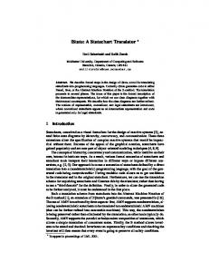
Figure 1 provides a Test ready UML Statechart model to specify the following ATM transaction behavior. Once a card is inserted and PIN validated, the transactions deposit, withdrawal and information display may be carried out. If invalid PIN entries are made, there is a limit to the number of re-entries. To generate executable tests from the UML Statechart model provided in Figure 1, the events PIN, WithdrawalAmount and ContinueTransaction are modeled as data-flow graphs as shown in Figure 1. Test statements are specified along relevant state transitions and in states. Guard conditions are placed along state transitions (for example, [PIN ~ Invalid] along the state transition from state ValidatePIN to Re-enterPIN). Note that the data generator nodes ValidPIN and InvalidPIN generate a valid PIN and an invalid PIN respectively(from a specified list of values). A list of valid PIN entries may be associated with the node ValidPIN by the tester. In a given path, either a ValidPIN or an InvalidPIN is selected from the data selector node PIN. Similarly, to model the event that a withdrawal amount less than the Balance or, greater than or equal to the Balance may be input by the user, the data selector node WithdrawalAmount is used. ValidWithdraw and InvalidWithdraw are data generator nodes each of which is modeled by the tester to generate a valid withdrawal amount or invalid withdrawal amount respectively. The tester introduces a variable called Balance into the model in Figure 1. Each time a deposit is made into the account, the variable Balance is updated (this is done through the execution of a task specified along the state transition AcceptCheque -> ContinueNextTransaction. In our tool Tasks are modeled as methods in Java).
3. PATHS IN THE TEST READY UML STATECHART MODEL Consider the paths in the UML Statechart in Figure 1(curly braces indicate cycles). Path1: Start -> (event:InsertCard) ->CardInserted ->{AcceptPIN -> (event: PIN) -> ValidatePIN -> guard condition: [PIN ~ Invalid] -> Re-enterPIN -> guard condition: [NoOfTrials guard condition: [NoOfTrials > Limit] -> AbortTransaction The sequence of state transitions in curly braces forms a cycle and the cycle terminates through the state transition Re-enterPIN -> AbortTransaction. .
Path2: Start -> (event:InsertCard) -> CardInserted -> AcceptPIN ->(event:PIN) -> ValidatePIN -> guard condition: [PIN~Valid] -> ATMTransactionBegin -> (event:Operation) -> OperationSelected -> guard Condition: [Operation ~ Information Display] InformationDisplayed -> ContinueNextTransaction -> guardCondition: [ContinueTransaction~No] -> ReturnCard -> End.
Figure 1 – ATM Transactions
The extended UML Statechart shown in Figure 1 depicts ATM Transaction scenarios. Definition: A Test Ready UML Statechart Model is obtained by annotating a UML Statechart model with events, guard
76
model and also specifies a depth factor used as a limit to expand cycles, (b) The Test generator first generates paths that may have cycles and (c) for test case or test script generation, a cycle is expanded a random number of times limited by the depth factor. Note that the cycle expansion step (c) is required only if a cyclic state transition is not guarded. If a cyclic state transition is guarded as the cycle in Path 1 above, then cycle expansion is carried out in step (b) above by the Test generator.
Test cases are instances of paths in the Test Ready UML Statechart Model. Note that an event modeled using a combination of data selector node, data aggregate node and/ or a data generator node is an extended context free grammar. We refer to it as an extended context free grammar because guard conditions may be specified along the input links of data selector nodes. Definition of an Extended Context Free Grammar Model: A test Ready UML Statechart model is an extended context free grammar model. Events attached to state transitions are modeled using a data selector node, a data aggregate node or a data generator node. A data generator node is a terminal in a CFG (ValidPIN, InvalidPIN, ValidWithdraw, InvalidWithdraw, NextTransaction, ExitTransaction), a data aggregate node is a non-terminal whose right hand side production consists of one or more non-terminals and a data selector node is a non-terminal with alternate production rules (PIN, WithdrawalAmount, ContinueTransaction, Operation).
4. EXTENDED CONTEXT FREE GRAMMAR MODEL The variable Balance is initialized and it is updated whenever there is a deposit or a withdrawal by executing a task specified along the respective transitions as shown below in the extended Context Free Grammar Model (of the Test Ready UML Statechart Model shown in Figure 1). The grammar below is a CFG extended with guard conditions along state transitions (enclosed within square brackets), tasks and scripts along transitions or alternate productions (for a detailed explanation about why a test ready UML Statechart model is a CFG, refer to Section 3. Events are shown in italics in the extended context free grammar below).
Definition of a Feasible Path: A feasible path is a path originating from the start node and terminating in a final state and for which all guard conditions along its state transitions are satisfied during test generation.
//ATM State Diagram Transitions Start -> InsertCard CardInserted CardInserted -> AcceptPIN AcceptPIN -> PIN ValidatePIN ValidatePIN -> ATMTransactionBegin , if [Pin~Valid] -> Re-enterPIN , if [PIN~invalid]
The test generation problem thus reduces to determining feasible paths in the Test Ready UML Statechart model, which is an extended context free grammar model, and creating instances of the paths. An event node (a data selector node which is a nonterminal with alternate production rules) attached to a state transition also contributes to a sub-path of a path from the initial state to a final state in the test ready UML Statechart model. The generation of paths starts from the start node with a state transition and exploring each one of the state transitions of the next node, provided guard condition, if any, along a state transition is satisfied. Guard conditions are based on the input link (a grammar rule) selected for a data selector node (or a nonterminal). Or, a guard condition is a boolean condition on user variables introduced by the tester in the model such as Balance > 1000 and set by tasks, if specified, along state transitions. A guard condition may also be a combination of both the above forms. All guard conditions are evaluated during path generation. A depthfirst traversal over the graph, which is a combination of the UML Statechart model and the event nodes represented as data-flow graphs, is used in determining feasible paths. If a guard condition is not satisfied, backtracking may be required which initially starts by exploring other transitions or inlinks of the current node and if none of them lead to a feasible path, then backtrack to the previous node and explore alternative state transitions or inlinks of event nodes. If backtracking continues right upto the start node or root node without finding any feasible paths, the test generator reports that it cannot find any more feasible paths.
Re-enterPIN -> AcceptPIN, if [ NoOfTrials AbortTransaction, if [NoOfTrials > Limit] ATMTransactionBegin -> Operation OperationSelected OperationSelected -> AcceptCheque, if [operation~Deposit] (Task: update var Balance) -> AcceptAmount, if [Operation ~ Withdraw] -> InformationDisplayed, if [Operation~InformationDisplay] -> Exit, if [Operation ~ Exit] AcceptCheque-> ContinueTransaction ContinueNextTransaction InformationDisplayed -> ContinueTransaction ContinueNextTransaction AcceptAmount -> WithdrawalAmount CheckAmount CheckAmount -> InsufficientBalance , if [WithdrawalAmount >= Balance] -> DispatchAmount , if [WithdrawalAmount < Balance]
Cycles are detected by maintaining a list of the nodes visited already in the path formed so far and if the next node is already present in the list of visited nodes of the path prefix, the cycle is marked. Once a state transition from the current node resulted in a cycle with a node already visited, then an alternate transition from the current node may terminate the path ending in a final state. Such a path has one or more cycles marked.
InsufficientBalance -> AcceptAmount DispatchAmount-> ContinueTransaction ContinueNextTransaction (Task: update var Balance)
The tool built based on Test Ready UML Statechart models has three phases (a) Tester creates a Test Ready UML Statechart
ContinueNextTransaction ->
77
ContinueNextTransaction -> ReturnCard, if [ContinueTransaction~No]
transition, pathPrefix#transition) detects the alternate transition(s) from the node through which a final state can be reached. The function considers different paths that may arise, if multiple state transitions from node participate in cycles.
ReturnCard -> End
The path generation algorithm is based on depth-first traversal.
//Events used in ATM example and their grammar Rules
PathGen(node, pathPrefix )
PIN -> validPIN -> InvalidPIN
begin if (transition = getNextTransition(node)) then nextNode = transition.destn else begin backtrack(node, transition) return end
ATMTransactionBegin, if [ContinueTransaction~Yes]
WithdrawalAmount -> ValidWithdraw -> InvalidWithdraw ContinueTransaction -> NextTransaction -> ExitTransaction
if nextNode is a finalStateNode then if guardCondition(transition) then begin executeTask(transition) appendPath(pathList) end else begin backtrack(node, transition) return end
Operation -> Deposit -> Withdraw -> InformationDisplay -> Exit The next section presents a path generation algorithm that we use based on depth-first traversal.
5. PATH GENERATION ALGORITHM The function PathGen(node, pathPrefix) is initially invoked on the start or the root node of the extended Context Free Grammar (start node of the Test Ready UML Statechart Model). Initially, pathPrefix is set to null as it indicates the portion of the path traversed so far. The function getNextTransition(node) checks if there is a transition from node through which a path is not yet explored, each time a node is visited (it basically checks the set of transitions from node minus the set of transitions from node explored so far). The function guardCondition(transition) returns true if the test generator determines after evaluation that the guard condition specified along the transition is true. If no guard condition is specified, then the guard condition is assumed to be true. The function executeTask(transition) executes the task specified along the transition. Execution of tasks may set Test Ready Model variables. The function backtrack(node) in a given state maintained by the test generator checks if there is an alternate transition from node that is not yet explored. If all transitions from node are already explored and no path could be generated, then the test generator backtracks to the previous node. The state maintained by the test generator consists of the state transitions explored so far from the current node, the path prefix generated so far and the parent node. In addition, the state of variables in the Test Ready Model is also maintained so that whenever there is backtracking, the user variables are reset to the values that they should hold at the backtrack point which may be a previous node or an alternate state transition, or an alternate inlink of a data selector event node. The function expandCycle(node, transition) expands the cycle as many times as required , if the cyclic sub-path consists of guard conditions. Otherwise, the cyclic subpath is just marked as a cycle. When test scripts are generated, the cycle is expanded limited by the depth factor specified by the user. The function genSuffixPathsExcludingTransitionsLeadingToCycle(node,
else if ( nextNode not present in pathPrefix) then if guardCondition(transition) then begin executeTask(transition) PathGen(nextNode, pathPrefix#transition ) end else begin backtrack(node, transition) return end else if guardCondition(transition) then begin executeTask(transition) expandCycle(node, transition) genSuffixPathsExcluding TransitionLeadingToCycle(node, transition, pathPrefix#transition) end else begin backtrack(node, transition) return end end
78
IsAtmAwaitingPinEntry(). These boolean functions provide an access to the current state of the running ATM Software. The test execution environment may be visualized as consisting of a thread running ATM Software itself and another running a test case (the synchronization code is not shown).
6. TEST SCRIPT GENERATION Consider the path Start -> (event: InsertCard) -> CardInserted -> {AcceptPIN -> (event: PIN) -> ValidatePIN -> guard condition: [PIN ~ Invalid] -> Re-enterPIN -> guard condition: [NoOfTrials guard condition: [NoOfTrials > Limit] -> AbortTransaction
//---------Start of TestCase1---------class TestCase1 { TestCase1() { try { int NoOfTrial=1; int limit=3; int balance=10000;
A test case is an instance of a path in the model. The tester provides along a state transition in the Test Ready UML Statechart model in Figure 1 just the portion of the test case or script that should be emitted, if the state transition is a part of the path from which the test case under construction is instantiated. It may be noted that a state transition may be a part of two or more paths, for example, Start ->CardInserted, or, ValidatePIN -> ATMTransactionBegin. Test statements (say in Java) may be specified along only chosen state transitions or as a part of chosen states to validate if the software under test reaches an expected state on the occurrence of a specified event. The tester, however, should have a coherent view of the snippets of code specified along state transitions so that the part of the test code specified along a state transition is coherent with the following test code in subsequent state transitions in a path. If a state transition is a part of multiple paths, the tester has to ensure that the test statements provided along the common state transition are coherent for all paths containing the state transition.
if(!atmProbeFunction.IsAtmInInitialState()) { throw new Exception("Atm not initialized : failed"); } if(!atmProbeFunction.AtmAwaitingCardInsertion()) { throw new Exception("Card not inserted: failed"); } //Set Card ID
In state based testing, it is essentially state sequencing that is checked. The testing problem for each test scenario is to consider the sequence of events specified by the corresponding path in the Test ready UML Statechart Model (behavioral diagram) and verify that as each event occurs, the ATM Software reaches the next state as specified by the Statechart. In general, a snippet of test code along a state transition checks if the Software Under Test (ATM Software) has not reached the expected state. If for an event that triggers a state transition, the Software Under Test does not reach the expected state, the implementation does not conform to the UML Statechart model. When a test is run, the test statements specified along a state transition throw an exception or generate an error message under the condition that the Software Under Test does not reach the expected state condition on the occurrence of the event along the state transition.
if(!atmProbeFunction.IsAtmAwaitingPinEntry()) { throw new Exception("Pin entry : failed"); } if(NoOfTrials (event: InsertCard) -> CardInserted -> {AcceptPIN -> (event: PIN) -> ValidatePIN -> guard condition: [PIN ~ Invalid] -> Re-enterPIN -> guard condition: [NoOfTrials guard condition: [NoOfTrials > Limit] -> AbortTransaction
if(NoOfTrials