Because of this increasing complexity, it has become essential to develop ..... SUBTYPE OF(named-element, failable-element); has-type: STRING; of-*.
,
Test Strategy Component of an Open Architecture lor Electronics Design and Support Tools
Leonard Haynes. Ph.D.* Sharon Goodall* Floyd Phillips*
william simpson. Ph.D.** John Shcppard**
*IntelligentAutomation, Inc Rockville, MD
**ARINC Research Corp. AMapolis. MD diffennces between the model formats used by the available tools thatmodclscannotbeportedfromonetooltoanother.
ABSTRACT This paper describes work being carried out under the auspices of the Artificial Intelligence, Expert System Tie to Automatic Test Equipment (AI-ESTATE) Committee of the IEEE Standards Coordinating Committee 20 (SCC-23). the goal of which is to develop a formal data model for dependency related information called an Information Flow Model (IFM). The papa includes the most important ENTITIES in the model. and a brief description of the model. The introduction attempts to place the IFM in the larger context of the Ada-Based Environment for Test, and briefiy describes other related efforts. The model included in this paper is not an approved draft of SCC-U). and should be viewed solely as conmbutions of the authors. Readers having comments on the model are invited to provide those comments to the authors, an address for which is included in stction 1 of the paper. 1.
The remainder of this paper describes the efforts of the Artificial Intelligence, Expert System Tie to Automatic Test Equipment (AI-ESTATE) Committee of the IEEE Standards Coordinating Committee U) (SCC-20) to develop a formal data modcl for dependency related information. The model for a Unit Under Test 0must specifically e n d the names of all ~ s t s . and for each test, encode what is l m e d from each of the possible test outcomes. In addition,related information includes the cost and time to perform the test. test equipment and technician skill levels required, and test reliability. The related information also includes component information including failure rates, cost to replace the component, groups of parts which normally fail together, etc. We call the total model an Information Flow Model (IFM) and we will use that name henceforth. The IFM must be generic and neutral in that it is adequate to model the information required by all the commercially available and U.S. Department of Defense tools which use dependency information.
Introduction
Modem systems are becoming increasingly complex. Because of this increasing complexity, it has become essential to develop automated tools to assist a designer in the development of reliable, testable, and maintainable equipment, and to develop automated tools to help the maintainer test and diagnose that equipment. During the equipment design phase. there is great advantage to being able to predict the testability and maintainability of a design before final commitment is made to full scale production. Once hardware is fielded, the complexity of a modcm system may necessitate automated tools which can assist a technician in both test and diagnosis of suspect equipment.
The IFM standard will allow portability of dependency models between tools. The larger goal is to allow reasoners which use the IFM model to be "plug compatible," in the true sense of the concept of an open architecture. This will require a set of SERVICES and a set of PROTOCOLS to be developed and standardkd. Applications which request only the standard set of services, and which adhere to the protocols will be able to use any compliant reasoner. This will still allow reasoners to provide a d d i t i d non-standard capabilities. Normally, these non-standard capabilities would be in the form of additional information which would be provided in response to the standard service requests. In this case, plug compatibility would not be lost even though applications might use the non-standard information, as long as they could function without the additional information if it were not available. W9rk on the details of a SERVICES interface for IFM based reasoners is progressing. but space does not allow inclusion of additional information nlated to that effort.
One of the most popular approaches to predicting the testability and maintainability of systems including those with both mechanical and electronic components is based on what is called a "dependency model." See references 1 and 2. The dependency model of equipment captures the relationship between the tests which can be performed at specific test points, and what is learned from each test. If data concerning the failure rates of individual components, the time and cost to perform tests. and other similar data is available, then analysis systems can use that dependency model and other data to compute the expected time and cost to diagnose the equipment, sparing requirements, etc. Hence dependency model based systems can provide valuable information during design time to predict life cycle costs, and to identify problems in the design which can be modifed to reduce life cycle costs, and to increase system availability.
The Information Flow Model is an absmct model, and will be represented in the International Standards Organization (EO) standard language called EXPRESS. EXPRESS is an implementation independent language. It does not specify how the data of a particular model will be stored in a computer, what database system will be used to access the data, etc. In order to allow the physical exchange of models, some physical structure must be agrtcd upon, and at this point, it appears that we will use IS0 STEP 10303.21. the physical file format normally used with EXPRESS. Given an EXPRESS model, and data for a particular device. STEP 10303.21 provides the actual exchange format for data.
Dependency models can also be used to dynamically compute an optimal test strategy to diagnose a specific p i a of equipment. Using a dependency model and the associated information as described above, the test sequence used to diagnose equipment can be optimized based on the equipment symptoms. technicians 4 test equipment available, current priorities, etc.
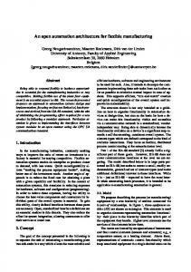
Figure 1 diagrams the architecture for the work of the AIESTATE Committee. plus icons which represent the IFM and other formal data models (the data model icons are not included in the approved AI-ESTATE architecture diagram.) In addition to the IFM data model, a fault tree model has been approved for distribution beyond SCC-20, and initial work has been done to define a standard SERVICES interface for both an IFM basea reasoner. and a fault tree reasoner. This ongoing work is indicated in the figure.
There are many tools available c o e a l l y which exploit dependency models. Companies which market dependency model based tools include ARINC Research Corporation (reference 1 and 2). DETEX Incorporated (reference 4). Automated Reasoning Corp (reference 5). Harris Corp., and BITE Inc. None of these tools interoperate. and the models used by one of these companies will not work with the products of any other companies. The lack of interoperability or portability of models is not due to complex technical problems. All of the tools which have been evaluated have similar dependency models. Thereare, however, enough
The Information Flow Model is only one small component
of the standanis which will be required to achieve an open system architecture for system test and diagnosis, and for testability analysis. There are other standards being developed by the AI-
49
CH3148-4/92/m-0049$1.0001992 IEEE
ESTATE Committee, and the work of the AI-ESTATE Committee #will hopefully fit within the larger framework of the Ada Based Environment for Test (ABET) effort. In this sense, the AIESTATE work can be thought of generally as the Test Strategy Layer of ABET. The AI-ESTATE Committee is eager to receive comments regarding the IFM model, and for expanded participation in all its efforts. Interested persons can contact Dr. Leonard Haynes. Resident, Intelligent Automation, Incorporated, 1370 Piccard Drive, Suite 210, Rockville, MD 20850 or call at (301) 990-2407.
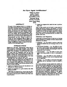
information learned from that test in terms of components known to be good as a result of a good test outcome, or components still suspected of being faulty as a result of a bad test outcome are tabulated. The tl. t2.cmd t3 shown below are tern performed on units C1. C2,and C3. In the figure, we see that t4 depends on component C3 and test t3. Also, test t3 depends on C1 and tl. These are referred to as first oder dependencies. By inference. t4 also depends on c l and tl. This is an example of a higher order dependency. 11
2. Benefits
For Concurrent Engineering to be effective. design data must be sharable and usable by design engineers, by test and maintenance system developers, by the logistics support community, by production personnel, and by training and related personnel. The standards we propose will help facilitate this sharing because it will allow dependency related information to be portable over a wide range of tools for both testability and maintainability analysis, and then will allow the same models to be used in the field for optimization of diagnosis.
2.2
Benefits of a standard interface for SERVICES
The development of standards appears to be most effective when individual standards aggregate together into an overall superstructure which relates each individual standard to the intent of the entire system. Layered architectuns have been very effective in providing that superstructureand therc are several examples of a family of standards which fit within a layered, hierarchical architecture. The best example of a layered architecture is the International Standards Organization (ISO) Open System Interconnection (OSI) architecture. OS1 is composed of seven layers, each of which defines specific services and protocols provided at that level. Each layer provides a set of standard services to the saucture above, independent of the particular implementation of that layer, and uses a standard set of services provided by the stn~cturebelow, again independent of the particular implementation of that layer. Compliant implementations are plug compatible, with many proven advantages. In the sense that an Information Flow Reasoner responds to commands from above, such as "run the next test" and uses the services of software and automatic test equipment at lower layers, its analogy with the OS1 model is clear. Our goal is to achieve the same portability and interchangability which has been achieved by the OS1 model. Work is progressing on the services and protocols for two classes of reasoners, however this work is just beginning. 3. Brief Example of a Dependency Model In dependency models,each of the available tests which can be performed is identified, and for each of those tests, the
BEST COPY AVAILABLE
t2
I
2.1 Benefits of the IFM Model Adoption of standards for information models will allow portability of models between tools. It would allow dependency model based tools to generate output which could k used directly by electronic test equipment to automatically perform tests. It would facilitate feedback of field experience to be used to update the models to provide improved diagnosis. It would encourage development of tools for automatically generating information models because a standard model format would increase the marketability of such a tool (it would be usable by many dependency model based tools.) Adoption of the proposed class of standards would also facilitate integration of "Interactive Elecmic Technical Manuals'' with the test strategy optimization tools since the interface to the tools would be standardized. Today, an information model might be developed during initial design to facilitate concurrent engineering analysis, but there is little likelihood that that same model would be usable on field service diagnosis equipment, again because of the incompatibility of the models used in the various available tools.
13
The concept of dependency modeling is very powerful, partly because it can be applied hierarchically. At one level, components can be single integrated circuits, switches, or similar individual components. At the next level, components can be larger aggregates such as a multiplexer. power supply, floating point multiplier circuit, etc. At yet the next level of aggregation, the same exact modelling concept can be used to model subsystems, and assess the testability of the system at that level. References 1 and 2 given much more detail on dependency models, and on the tools which use these models. It should be mentioned that dependency models are not limited to electronic equipment. Dependency-based testability analysis has been used in many domains with q u a l success. The term "dependency" is often used in the context of "fault dictionary" approaches to electronic system diagnosis, and this has caused considerable problems in describing the standard we are proposing to those familiar with fault dictionary based tools. Them are several very fundamental differences between a dependency model as described in this paper, and dependency as used in fault dictionary approaches. In fault dictionary approaches, an extensive sequence of test vectors are applied to a system under test, and a set of system outputs are simultaneously monitored. In the presence of faults, some of the outputs will be incorrect at various points in time, and the resulting fault v r + x is analyzed after the entire test sequence is applied to the device under test. In general, for each failed output, analysis techniques look for which components affect the failed outputs, and hence for those components whose failure could cause the output in question to fail. The dependency in this context is between system output and components. independent of which test is being executed. There is only one "test" and it tests all components simultaneously. There is only one set of outputs and it remains the same through the entire analysis process. For dependency models as we use the term, there an many tests, each with its own distinct set of components which are tested by that test. We assume that for each test, what is learned from each of the distinct outcomes of that test is known a priori and encoded in the model. The primary function of e dependency model is to select an optimal next test in terms of a set of criteria. In a fault dictionary approach, there is only one test sequence so even at the most basic level, the two approaches are entirely different. In order to meet the objective of determination of the optimal sequence of tests to perform, special inference .'ypes. groups, weights, etc also need to be considered. When this additional information is added to dependency information, HG Li ,he result an information flow model. 4.
The Information Flow :.Le1
The IFM is quite compact and elegant. with only 29 ENTITIES. The model is included below. Only the consistency rules have been excluded to meet the paper page limit, and the format of normal EXPRESS has been compressed to save space.
replaccmell~level: replacantnt-tim: replaccment-mt replacemen-skill-level:
S(3HEMAIFM~mOdek TYPE status =ENUMERATION OF (bad,good); TYPE ~ C S - ~ ~ - I I O = ENUMERATION OF (yes, no); TYPE referenCegOint-type =ENUMERATIONOF (input, output, inout, internal-location); TYPE --type = ENUMERATION OF (and-op, OLOP, mt-op); TYPE relation-type = ENUMERATION OF (before, equals. after); TYPE multiple-failure-group-id = INTEGER; TYPE arbitmy-gmup-id = INTEGER; TYPE unit-id = INTEGER, TYPE unit-type-id = INTEGER; TYPE aspect-id = INTEGER; TYPE encapsulated-test-id = INTEGER, TYPE test-id = INTEGER (* identifies either an encapsdated test or a unit test *) TYPE setup-operation-id = INTEGER TYPE access-opention-id = INTEGER, TYPE test-outcome-id = INTEGER TYPE referencepint-id = INTEGER TYPE tem-id = INTEGER ENTITY model; header-information: unit-model: type-library: testlibrary : group-information: test-related-li braries: END-ENTITY;
h
mc
failm-late: retest-& END-ENTITY;
ENTITY unit SUBTYPE OF(named-element, failable-element); STRING; has-type: of-* unit_typc_id; has-parts: SET [O?] OF unis has-aspects: SET [O?] OF aspect; END--
m
unit-typc SUBTYPE OF(&-element,
failable-element);
END-;
m
aspcct SUBTYPE OF(named-element); failm-rate: OPTIONAL REAL; relative-likelihood: OPTIONAL REAL, END-rn;
w
SET IO?]OF unit-type; SET [O?] OF unit-tesc
ENTITY headm, Pnparer: organization: description: mcdel-requ+ments: model-creaaon-W last-modified-date: classification: replacement-time-units: replacement-cost-units: test-time-units: test-cost-units: failure-units: retest-ok-units: setup-time-units: setup-cost-units: access-time-units:
access-cost-units: END-Em, m~ U D S : arbikuyz&ups: mult-failuremps: END-EW,
criticality:
OPTIONALSTRING; OPTIONALREAL; OPTIONAL REAL; OPTIONAL INTEGER; OPTIONAL INTEGER; OPTIONALREAL; OPTIONAL REAL;
groups; libraries;
?g%EsL-element); member-aspects: member-units: END-Ern;
SET [O:?] OF aspect-id; SET [O?] OF unit-id;
STRING; OPTIONAL STRING, OPTIONAL STRING, OPTIONAL STRING, STRING; STRING; STRING; OPTIONAL STRING, OPTIONAL STRING; OPTIONAL STRING; OPTIONAL STRING, OPTIONAL STRING, OPTIONAL STRING, OPTIONAL STRING, OPTIONAL STRING, OPTIONAL STRING, OPTIONAL STRING,
ENTITY multiple-failuremp SUBTYPE OF(&-element, member-aspects: member-units: END-ENTITY,
SET [ O ? ] OF a s y - i d ;
unit-test SUBTYPE OF(named-element); SET [O?] OF unit-test; has-unit-tests: has-encapsulated-tests: SET [O?] OF encapsulated-tess END-E-, ENTITY encapsulated-test SUBTYPE OF (named-element); is-measurable: yes-or-no; time-to-perform: OPTIONAL REAL, cost-to-perfoxm: OPTIONAL REAL, rcq_setup-operations: SET[O?] OF setup-operation-id; SET[o:?] OF acccss-operation-id; rcqs-access-ops: reqs-technickm SET [O?] OF technician, rcqs-eqmpment: SET [O?] OF STRING, has-stimulationqts: SET [O?]OF referencepin-id; has-infojts: SET [O?] OF referencepint-id, has-outcomes: SET [l:?]OF test-outcm; has-rel-to-other-tests: SET [a?]OF test-relatioq END-Em
SET [O?] OF arbiaar)[_group; SET [ O ? ] OF mult-fadure-group;
terms:
END-Em,
SET [O?] OF setup-operation; SET [O?] OF acctss_opcration; SET [O?] OF referencepiny SET [O?] OF tmn;
ENTITY operation-element ABSTRACT SUPERTYPE; cost
tim: ENTITY named-element ABSTRACT SUPERTYPE ; name:
description:
id: UNIQUE id; END-Em,
SET [ O ? ] OF unit-&
m
E
ENTITY libraries; setup-operations: access~opelations: reference-points:
failable-element);
END-ENTITY,
STRING OPTIONAL STRING INTEGER;
ENTITY failable-element ABSTRAm SUPERTYPE ;
ENTITY setup-operation SUBTYPE OF(&-element, END-Em,
operation-element);
ENTITY access-operation SUBTYPE OF(&-element, END-ENTITY,
operation-element);
E"technician;
51
OPTIONAL REAL; OPTIONALREAL,
requires-skill-level: rtquires_Ckirrancc: requins_authority:
INTEGER; INTEGER; INTEGER;
E " Y unit-status; for-unit certainty: has-status: END-Em
E N D _ m ; E
M reference-point SUBTYPEOF(named-elemnt); has-type: OPTIONAL refaencegointtype; location: SET [O?] OF dercnce-point-locatim END-Em, ENTlTY refercnccpint_location; on-unit: at-lalxk END-E"W
E"TITy;
unit-id; OpllONAL STRING,
ENlTIY arbitmypp-status; for-arbitmysup: certainty:
has-status: END-Ern, OCcUIs:
related-tests: END-ENTITY, END-SCHEMA,
UNIT The most essential element of the IFM is the Unit. Since Unit is a Named Element, it includes attributes such as name, a textual description of the equipment, and a unique id (seeENTITY Named-Element in the IFM). The s t r u c m of the equipment being modelled is expressed recursively: Units can be composed of parts which are themselves unique units. The format of the has-parts attribute for Units forces the hierarchy of Unit entities to be unique, exclusive and untangled. A Unit which is a part of one particular Unit entity will never appear as part of another Unit entity.
operator-type;
Each unit entity is associated with a Unit Type entity. Type information for units in the IFM is stored in the library of Unit Types. General information common to all units of the particular type relating to replacement of the unit and statistics on failure rates is included in the Unit Type entity (both Unit and Unit Type entities are subtypes of the Failable Element entity). Multiple Unit entities may reference the same Unit Type entity. Sometimes it may be necessary to override the Unit Type information which is automatically inherited by a Unit entity. For this purpose optional infomation about replacement level, replacement cost, replacement skill level, criticality, failure rate and Retest OK rate may be spectfied for a Unit entity.
ENTITY term
SUBTYPE OF(named-element );
OPnONAL test-status OPTIONAL aspect-status; OPTIONAL unit-status OPTIONAL arb_group-staNs; is-mult-failure~up-status: OPTIONqL mult-fdure-gmup-status; WHERE only-one-entry : EXISTS(is-test-status) XOR EXISTS(is-aspect-status)XOR EXISTS(is-unit-status) XOR is-test-status: iS-aspeCt-StaNS: iS-Ult-StaNS: is-arb-gmup-status:
UNIT TYPE
A library of Unit Type information is pan of the Information Flow Model. Type information inc!udes attributes related to failure such as the maintenance level at which it is replaceable, time, cost and skill level required to replace units of this type and the Criticality of this type of unit. Additional type infomanon pertains to unit failure statistics and includes attributes such as failure rate, and Retest OK rate of units of this type. This information is inherited by Units of this type unless the Unit entity specifically includes values for the replacement and failure statistic related attributes which are common to both entities.
EXISTS(is-arbinary_group-status) XOR EXISTS(is_multiple-f~l~~up_status); END-ENTITY;
ENTITY aspect-status; for-aspect certainty: has-status: END-ENTITY;
aspect_id; OPTIONAL REAL, status;
relation-typc; SET [1:?I OF test-id;
A few key points related to the model are included below:
expression2: OPTIONAL expression; WHERE not-is-unw-optor: (EXISTS(expression2)AND operator o not-op) OR (operator = not-op) AND (NOT (EXISTS (expression2)))); END-ENTITY;
encapsulated-test-id; OPTIONAL REAL;
status;
S. Discussion of the IFM Model
expression;
ENTITY test-status for-test: ccnainty: has-outcome: END-ENTITY;
arbitmysup-id;
OPTIONALREAL;
ENTITY testrelation;
ENTITY expression; OPTIONAL tcrm_id; isa-term: isa-parenthesized-expr: OPTIONAL expression; isa-tuple: OpIlONAL tupk WHERE onlv one enw: ~ ~ i S ~ ~ ( i s a - t ;XOK rm) EXlSTS(isa-parenthesi~-exprj XOR EXISTS(isa-tuple); END-Em,
OpCIXtOK
status;
ENTITY multiple-failuresup-status; multiple-failun-group-id; for-mult-failure-gmup: catainty: OPTIONALREAL; has-status: -;
ENTITY test-outmme SUBTYPE O F ( d - e I e m e n t ) ; pmb-false-outcome: OPTIONAL REAL, base-confidence: OPTIONALREAL; implies-good-list: OPTIONAL expression; implies-bad-list: OPTIONAL expression; SET [O?] OF test-id; exclude-for-safety : END-ENTITY;
E N n n tuple; expression1 :
unit-id; OPTIONAL REAL,
ASPEa
test-outcome-id;
Units are modelled by dividing their failure modes from a test perspective into aspects. An example of an aspect would be a counterkhift register combination which can function as a counter or shift register. That unit can fail by not being able to count, or by not being able to shift, or both. Certain tests will test the counter function and others will test the shift register function and still other
52
time and cost. and setup time and cost. The model allows any number of access operation and setup operation attributes to be specitled. The physical interpretation of the sets is that several operations may be feasible to provide access to a specific test. Some may also provide access to other tests so there is an optimization issue. The assumption is that any of the operations identified in the set of acccs-opemtions will provide access for the requixed test. The same is true for setup-opemtions.
tests may test both so the model must allow modelling of the single physical unit as two separate "virtual units." An Aspect is a subtype of the Named Element entity and has additional attributes for a failure rate and a relative likelihood. The failure rate is a book value for this aspect. The relative likelihood indicates how likely this unit is to fail in this failure mode with respect to other failure modes for the unit. ARBITRARY GROUP
Encapsulated Tests also include a set of required technicians and a set of requkd test equipment. This information is required by the inference mechanism in order for it to be aware of what resources are required to execute what tests. In the event that some
Entity Arbitrary Group provides a means of grouping Unit entities in the IFM. Note that while units and aspects of the Unit hierarchy are distinct entities, the concept of an arbitrary group in the IFM is specifically designed to provide an alternative partitioning of the Units and Aspects in the Unit hierarchy. Having the has-parts attribute contain a set of unit-ids instead of Units, forces the Arbitrary Group to reference Unit entities previously defined in the Unit hierarchy; the same holds true for Aspects.
resources are not available, the inference mechanism can still proceed with the diagnosis using the tests for which the required resources are available. An attribute identifying whether a test is a built-in test or not has not h e n included in the IFM since this information is derivable from the model: if a test requires neither technicians nor equipment it must be a built-in test.
The Arbitrary Group entity includes attributes which identify its name, a description of the group, a unique identifier number and the list of Aspect and Unit entities which define the group. Dependencies in the model can be established between test outcomes and arbitrary groups.
The attribute has-relation-to-other-tests provides a means of expressing how a test relates temporally to other tests. This attribute contains a set of Test Relation entities which specify the set of related tests and the temporal relationship to those tests. The tests identifed in the list of related tests may either refer to specific encapsulated tests or to unit tests.
MULTIPLE FAILURE GROUP
The kemel relationships for the Encapsulated Test is the set of two or more Test Outcomes. It is in this relationship that the dependency information is modelled. This will be explained under the entity Test Outcome.
Entity Multiple Failure Group provides another means of grouping Unit entities. In this case, however, the grouping is not purely arbitrary but indicates that the Unit and Aspect entity group members tend to fail together within the system being modelled. By grouping the set of Unit and Aspect failures together, they can be treated as a single failure in the modeL Attributes of the Multiple Failure Group include the group name, a description of the group, a unique identifier number (used in establishing dependencies within test outcomes) and a list of Unit and Aspect entities which comprise the group. Also included in the Multiple Failure Group entity are attributes for describing failure statistics and xcplacement infomution for the group.
TEST_OUTCOME The IFM does not restrict test outcomes to GOOD or BAD. It allows any number of test cutcomes. each identified as a Named Element, alon- with attributes identifying the probability of this outcome o c c d h g falsely and the base confidence in this particular oufcomc. The essence of a dependency model is "what is learned from each possible outcome of each test." IFM models this learned information in the most general way, so that redundant systems can be modelled as well as conventional systems. The two attributes which capture the dependency information are requiresjood-list and requires-bad-list. The interpretationof the good l i t is that the resulting expression defines what is learned to be good as a result of that particular test outcome. The interpretation of the bad list is that the nsulting expression defines what is learned to be bad as a result of that particular test outcome.
UNIT TEST The third major category of Entities in this model are those related to specific tests. The basic premise on which the IFM is based is that tests are encapsulated tests. This means that a test is identified primarily by a unique identifier and that the details of the test itself are contained in other models which are referenced through a symbolic name, but not otherwise included in the IFM. As far as any inference mechanism which uses the model is concerned, all tests are encapsulated tests. Entity Unit Test allows encapsulated tests to be identified, for naming purposes. with higher level aggregations. This is solely for convenience and the information in entity Unit Test will not be used during inference. Entity Unit Test allows tests to be identifed as a subtype of Named Element, and any Unit Test can be composed of other Unit Tests and/or Encapsulated Tests.
Test outcomes are formulated in logical expressions in the good list and bad list attribiites. The entities Expression, Tuple and Term implement the logical expression, shown below in BNF form, in the EXPRESS language: expression := term I ( expression ) ltuple tuple := unary-operator expression I expression binary-operator expression term := test-status I aspect-status I unit-status I multiple-failure-group-status 1 arbimy-gmup-status unary_operator:= NOT binary_operator := OR I AND
ENCAPSULATEDTEST An encapsulated test is an atomic element It is modclled as a subtype of the Named Element entity. along with optional informationregarding the timeand cost to perform the test. l
Reference points have been added to the IFM so that the coxality of various tests can be identified. Each encapsulated test
where AND has precedence over OR, NOT has precedence over AND and parentheses have the highest precedence. The three attributes of the entity Expression capture the three possible forms of a logical expression in this syntax: an expression is either a Tam. a parenthesized Expression or a Tuple.
may optionally have a set of stimulation (input) points and a set of information gathering (output) points. The Reference h i n t may k-ve a type identified (one of input, output, inout, or internal-location) and optionally have a set of Locations. Each Reference Point Location optionally identifies a particular unit on which the point is located and a textual description further labelling the reference point.
The notion of a "symptom"is not included in the model as a unique type of Test Outcome. There appcars to be great differenas between the way different tools handle symptoms, and even in the meaning of the word. The model attempts to be as general as
An encapsulated test includes entities which define access
53
feasible. so we have decided not to distinguish symptoms as a separate category because the data which is generally used to identify symptoms is alnady available in the model. Tests include the information as to the number and skill levels of technicians requiredtoperformatest.thetimeandcostofeochtesfandthe test quipment nquired to perform a test. If a particular tool (WSTA for example) defines a Symptom as the result of a "cheap test" by some definition of "cheap" then this information is available and ''symptoms" can be distinguished from other tests by these measures. Information available at no cost will be modelled as a test regardless of other information. symptom not withstanding.
6.1
Our cumnt view of the services interface is that an IFMbased reasoner provides information regarding optimal test strategy, and can be viewed as an abstract knowledge base. We can represent the required ENTITLES and their relationships in EXPRESS just as we described the IFM model itself in EXPRESS. EXPRESS is implementation independent. Any language can be used to store the actual data, and any query language can be used to access the data. In order to achieve plug compatibility, some decisions must be made as to the specific command formats, but this is a mvial problem compared to the issue of what information must be provided to an IFM reasoner, and what results are produced. SQL, for example, could be adopted as the standard method for accessing the IFM-reasoner.
ASPECT STATUS, UNlT STATUS, MULTIPLE FAILURE GROUP STATUS. ARBITRARY GROUP STATUS
Using this paradigm, a l l rcquests for service an equivalent
All of these entities allow specification of the particular aspect, unit or group as being GOOD or BAD, and the certainty with which this information is known.
to reads and writes into the "knowledge base." The writes to this data base art used to pass parameters to the reasoner, and to
establish the Criterion for a given session. As an example, assume it is desired to set the priority for diagnosis to emphasize the time required to diagnose a problem. Setting this priority would be equivalent to writing a value into the priority values defined below. An SQL command could be used to effect this write.
TEST STATUS This entity allows the results of tests to be included in the logical expression described above, permitting first order dependencies to be described in the IFM. It is not clear at this time whether a certainty value is required.
ENTlTY reasoner-paramete-data; conmuer~model~# maintenance-level: max~~t~for~Call0Ut max-amb_group-size-for-callou it: max~repl~timc~for~~out m&c&ty-for-dout: pnonty -on-repair-mt: priority-OIl-Rpair_dme: priority-on-diagnosis-cost: priority-on-diagnosis-time:
TECHNICIAN TEST EQUIPMENT Tests shall be further modelled to include the set of Test Equipment and the set of Technicians required to perform the test. For entity Technician, the number and skill levels of the technicians required to perform a test is included. The equipment required to perform a test is included in the model so that in the event specific equipment is not available, the system can proceed with diagnosis by recommending other tests which can be performed. Links to other models for description of test equipmentcan be provided exteanal to the IFM. 6.
Services Paradigm
priority-OIl-total-liXIh%
priority-on-total-cost: pnority-on-repair-accmc non-standard_pars:
STRING; STRING; COX
INTEGER time;
E!REAL; REAL; REAL;
REAL; y:
REAL;
REAL;
non-standard_d;
END-,
Services Interface
A command to compute the next test to execute would be equivalent to a read from the value next-test in the followingentity structure. The reasoner would then compute the value which was retumed as a result of the query.
As described in section 2.2 of this paper, one of the goals of the AI-ESTATE Committee of SCC-20 is to develop a set of standardswhich support plug compatibilitybetween componentsof an AI-ESTATE compliant system. In order to achieve this goal, it is essential to define the SERVICES which components of the system provide to other components. The following discussion deals with the SERVICES interface to an IFM-based reasoner which will provide test strategy services to the levels above, and exploit the test equipment at the lower levels to actually perform tests.
ENTITY nasoncr_dagnosis-datata; predicted-*-to-diag: pre+cted-tlme-to-repair prcd+d-cost-to-diag: PrCdlcted-cost-to-Rp~ current-amb-gmup: unit-type: unit-selial-# ament-best-dout explaination: last-test last-test-result Ilext-test: tCSt-reSulC non-standard-data: END-ENTITY,
The SERVICES interface to an IFM-based reasoner must not restrict the manner in which services arc provided, nor can it prevent components from providing non-standard capabilities. Our standards should allow competitive advantage and flexibility to be creative. yet conforming componentsmust still be plug compatible. We believe these goals can be achieved, and our initial approach is discussed below. There are several paradigms possible to specify SERVICES, and the AI-ESTATE Committee is still evaluating possibilities. No formal decisions have been made, even as to the basic paradigm for the specificationof SERVICES. There has also been no formal discussion as to what SERVICES should be included in the standard. There has, in fact, not been a formal vote even as to the need for a SERVICES interface so this work is in its infancy. With these strong caviots, the following paragraphs describe the a u t h o r s ' current thinking on these issues. Specifically, the following is not approved by the SCC-20 or by the AI-ESTATE Committee.
It can be seen that the ENTITY reasoner-diagnostic-data &ta includes non-standard-data as an atmbute. This non-stancan represent additional functionality. or it can represent additional information provided in response to the standard functionality beyond the standardized response data. If the non-standard features are in the form of additional information beyond the required answers, then these non-standardcapabilities do not even result in a loss of plug compatibility. As an example, a reasoner computes and then provides the test-id of the next test to execute in response to a "read" from the next-test attribute. This is the standard response. A specific reasoner uses non-standard
54
attributes to provide a set of other tests which could be executed next with close to equal efficiency. An application using this capability would read these values and might exploit one of the alternativechoices. If the reasoner were replaced with a compliant reasoner which did not provide that additional information, then when the reasoner tried to access the alternative choices, it would receive "null" responses which it would then ignore. hence plug compatibility has not been lost. The current "strawman" list of "services"is shown below although we must emphasize again that this list is incomplete, has not been approved by any Committee. and is to be interpreted only as the opinion of the authors. 6.2
Service Interface ENTITIES
ENTITY nasoner-admin-da@ reasoner-id user-list: current-user-logon: current-time: current-date: replacement-level:
non-standard-admin-data:
STRING; SET[&?] OF user-list-& user-list-& cumnt-fime-& current-date-& STRING; non-standard-&
END-ENTITY, ENTITY user-list-& user-name: User-kk userjassword: user-skill-level: clearance: authority: non-standard-user-data: END-Em
STRING, STRING, STRING: INTEGER; INTEGER INTEGER non-standard_&
ENTITY m n e r - i & reasoner-name: reasoner-version-number: reasoner-serial-number reasoner-contact-name: reasoner-wntactj hone-# END-ENlTl-Y
STRING; INTEGER STRING, STRING; STRING;
ENTITY user-admin-data; user-logon-data: END-ENTlTY;
user-list-d
ENTITY reasoner-status-data; status: cant-ta& expected-time-to-complete: time-expended-cant-task time-expended-this-session: time-since-last-backup: allowable-user-options: non-standard-status-dam END-ENlllY
status-& current-task-k
t amz
error requires restart, no model loaded);
archive-event-d;
STRING; STRING.
E N D - m . ENTITY archive-event-& test-event callout-event logon_Cvent
annmand-event END-ENTITY
OPTIONAL test-id; OFTXONALunit-id; OPTIONALusa-id: OPTIONALcommand_id
session-mdc: annoration: mdc-since-last-sent: END-ENTITY,
ENTITY mck-unit-data; specifies-unit-id-to-repair: spccifies-unit-said-no-to-tepak specifies-unit-type-to-repair spccifies_tcchnician-kk
has-unit-test-data:
S h K
S"g.
smg.
SET[O:?] OF mdc-test&@
timt;
2
total~isoMm-time: total-repail-time: units-@aced: final-unit-status: non-standard-&-dam END-ENTITY;
SET(O?] OF unit-id; status;
non-standard-&
E " Y mdc-daa reasoner-id IFM-model-id unit-id unit-type: technician-id session-# test-dam initiation-linE
isolation^^
ENTITY current-task-&
total-=pair-fjmc
INTEGER STRING, STRING;
E"Y user~rcsource-dam tech-available: equipment-available: parts-inventory: equipment-unavailable:
ENTlTY archivegortion; ad6ve-k archive-evenc archive-text archi-J-annotaIim: non-standard-=hive-data:
SmOnOF archive-portion;
time:
ENUMERATION-OF(executing, waiting for task.
task~namei task-descnption: END-ENTITY
ENTITY mner-archive-da@ session-archive: E N D - m
initiation_tim:
END-ENTTI'Y taskid;
SET[l:?] technician;
ENTITY nasoner-mdc-u
ENTITY status-& status:
ENTITY technician-available-&
tech-available-& S w l : ? ]OF equipment-id; parts-inventory-& Sml:OF ?] equipment-id;
units-=placed: find-unit-status: END-ENlTlY
E " Y mdc-test-daw test-namc: test-kk result:
S h g .
String.
callout
outcome-id; set [O?] of unit-callout;
action-taken:
set [O?] of un-ti*,
ENTITY non-standard_d; non-std-item-name: any-strings: any-ld.X any-integers: END-Em,
note: unit-status-after-action: action_time:
aEtim-mr non-standard-mdc-test-dam END-rn;
7.
ENnn unit-rq&, component-id: Compon~t-type: old-component-serial-no: new-component-serial-no: rcplaced:
STRING; SEl70?] of STRING;
SEITO?]of REAL;
SET[o:?] of INTEGER,
Conclusions
The Information Row Model and the Services model are two key elements required to achieve an Open Architecture for dependency-based test strategy tools. Similar models have also been developed for fault we-based reasoners. Other work will attempt to develop standard models and services for other types of reasoners including rule-based reasoners, neural-net reasoners, fault dictionary-based reasoners, etc. Most test strategy reasoners will provide similar services. and the union of these services will become the general interface for test strategy reasoners. with conformanceclasses defmed for the individualreasoner types.
~-rt?air-action:
=pa!r-t=: repalr-cost non-standanl-repair-data: END-ENTITY,
ENTITY unit-callouc unit-id unit-type END-ENTITY;
Hopefully, products which conform to the standards developed by the AI-ESTATE Committee will then be plug compatible test strategy components within the larger Ada Based Environment for Test.
ENTITY reasoner-parameter-der_data; controller-model-# controller_model-#-& maintenance-level: STRING;
8.
Acknowledgements
The research which provides the foundation for the model development described in this paper is funded by the Wright Laboratory, Air Force Systems Command, Wright-Patterson AFB, Ohio. Technical Direction is provided by Mr. James Poindexter, (MRLCWTR). Mr. Poindexter has made many important suggestions regarding our work, and his contributions are in part responsible for the project's success to date.
priority-on-repair-time: priority-on-diagnosis-cost :
priority-on-diagnosis-time: References
*ty-on_w-time:
pnonty-on-total-cost : priority-on-repair-accuracy : non-standard_parameter-data: END-ENTITY,
1. Simpson, W.. and Sheppard. J., "System Complexity and Integrated Diagnostics," IEEE Design and Test of Computers, Volume 8, number 3, Sept. 91, pgs 16-30.
2. Sheppard, J., and Simpson, W.."A Mathematical Model for Integrated Diagnostics," EEE Design and Test of Computers, Volume 8, number 4, Dec. 91, pgs 25-38.
E N " msoner-diagnosis-daw @cted-time-to-diag: predlcted-time-to-repo_repair: predicted-cost-to-diag : predicted-cost-to-repair: current-ambituitymup: unit-type: unit-seriaI-# current-best-callout: explaination: last-test: last-test-result: next-test: non-standard-diagdata: END-ENTITY,
3. Keiner, W.. "A Navy Approach to Integrated Diagnostics," AutcTzstCon 90,San Antonio, TX Sept. 1990. 4. "STAMP User's Manual," DETEX Systems Inc., Orange, CA.
5. Cantone. R.. and Caserta. P., "Evaluating the Economic Impact of an Expert Fault Diagnosis System: The ICAT Experience," Roc of the 3rd IEEE Symposium on Intelligent Control, Los Alamitos, CA, 1988.
Fwn 1
ENTITY user-diagnosis-data; run-test manual-test-result: END-Em,
encapsuIated-test-i& manuaI-test-result-&
E " I Y ATE-diagnosis-&& run-test: test-result: END-E"Y
56
ACESTATE *rrnn