Testing And validation Of Simulation Tools Of HVAC Mechanical
Recommend Documents
imposes the refrigerant mass flow rate through the cycle. ... The refrigerant flow rate displaced by the compressor .... The fan control variable is proportional to.
TESTING AND VALIDATION OF SIMULATION TOOLS OF HVAC. MECHANICAL ... of Building Energy Simulation Tools). The goal of ... the simulation programs to predict the performance .... this validation task is designed for application in any.
ABSTRACT. Technical systems are becoming increasingly integrated,. e.g. because of the intensive use of software due to demands on energy efficiency, ...
Aug 19, 2015 - framework and culture of test-driven development is essential [Beck, 2002, Osherove, 2013]. ... of this test in Python code. .... subproject of OpenWorm is a simple API that provides a repository of information about C. elegans.
Aug 13, 2001 - new software. Selected test results are presented below along with discussion of lessons learned. ANALYTICAL â BEPAC/BLAND.
Aug 13, 2001 - Comparative - BESTEST/ASHRAE Standard ... the same material on all six sides with free-floating ... transfer, and ground coupling. .... 5:00 6:00 7:00 8:00 9:00 10:00 11:00 12:00 13:00 14:00 15:00 16:00 17:00 18:00 19:00.
communication, such as IEEE 1344 in 1995, IEEE C37.118, IEEE C37.118.1-2011 and IEEE ... IEEE format bus-branch network model such as two-area system, Western Electricity ...... âHelpâ button directs user to the LSE manual. A status ...... 102. [
HVAC controller design and test. They take into account static and dynamic phenomena, which are necessary to assess, control functions in terms of comfort and ...
application is tested with two different controllers: a high performance and low performance controllers. The same controllers are used in the two different testing ...
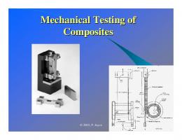
ASTM. SACMA. Lamina/Laminate. Mechanical Tests. 0°/Warp tension. D3039 ...
Standard for high modulus carbon fiber composites (1980s). ➢ 0.5” gage length ...
environment for UAV software are the modeling and simulation of the environment and the ... field of UAVs (unmanned aerial vehicles) they have lead to low-cost .... is send by the software, the value is used to divide the force that is generated by .
environment for UAV software are the modeling and simulation of the environment ... autopilot approaches for UAVs [1], cannot be used. The unit operates on its ...
This paper presents a multiphase simulation of evaporator in automotive air conditioning system was done by using R134a and R1234yf as working fluid ...
automation (e.g., automated vehicles (AV) and self-driving cars), and ... W. Sadek are affiliated with University at Buffalo, Buffalo, NY 14260 (email: {yunfeiho ...
frameworks have been proposed in civil engineering, computer science, and related .... Aimsun [15] [16] [17] [18] [19] provide an extensive API to their traffic simulator, so ... in C++, while Python replaced oTcl to provide a scripting capability.
Chicago are OA damper stuck at 100% position, blocked OA screen, supply air temperature offset, boiler/chiller fouling, and chiller refrigerant under/overcharge.
only whole muscle testing (In vivo and In situ) is discussed. There are several ...
The manual muscle test has strict and well-defined rules for the subject's posture
...
with the MATLAB optimization toolbox, which provides various powerful mathematical ... robust and versatile communication architecture between them.
of generic components (that are known to have several possible ... These processes will be subdived into five basic types: *. Storage processes accumulate and ...
Aria that generates testing and analysis tools based. on an abstract semantics graph representation for C. and C++ called Reprise. Aria itself was generated by.
According to Tarski, a model is a vehicle that can be used to ... programs. Furthermore, related empirical models are proposed. Successful ...... Montreal, Canada. ..... Mechanical, historical, philosophical or psychoanalytical explanations for ...
It is currently scheduled to be deployed on a Shuttle Hitchhiker flight. ..... The shape and area of the hysteresis loop depend upon the material used in the rod.
(ISCCSs) based on parabolic troughs using CO2 as heat transfer fluid was reported ... In work of Rovira et al [4], different ISCC configurations including a solar field ... evaporate part of the high pressure steam of a bottoming Rankine cycle with .
(potential) users in a model and in the information derived from the model that they ... If the purpose of a model is to answer a variety of questions ... the third party conducts an evaluation to determine its va- lidity. Based upon this validation,
Testing And validation Of Simulation Tools Of HVAC Mechanical
TESTING AND VALIDATION OF SIMULATION TOOLS OF HVAC ... Building Energy Simulation Tools). ... coil performance at different part load conditions.
Eleventh International IBPSA Conference Glasgow, Scotland July 27-30, 2009
TESTING AND VALIDATION OF SIMULATION TOOLS OF HVAC MECHANICAL EQUIPMENT INCLUDING THEIR CONTROL STRATEGIES. PART II: VALIDATION OF COOLING AND HEATING COIL MODELS Clemens Felsmann1, Jean Lebrun2, Vincent Lemort2 and Aad Wijsman3 1 Technical University of Dresden, Germany 2 Thermodynamics Laboratory, University of Liège, Belgium 3 Vabi Software bv, Delft, The Netherlands
ABSTRACT This paper presents detailed information about testing and validation of cooling and heating coil models. The work has been carried out under Subtask D of the International Energy Agency’s SHC Task 34/ECBCS Annex 43 (Testing and Validation of Building Energy Simulation Tools). The goal of this Subtask (Mechanical Equipment and Control Strategies) was to develop and test methods that would help evaluating, diagnosing and correcting HVAC mechanical equipment simulation software.
conditions of the system have been slightly changed which has to be taken into account for the model validation. These modifications are for instance in terms of physical properties of chilled water and calibration of sensors. Figure 2 shows the concentration profile of Propylen-Glycol percentage of chilled water and periods of chilled water tests I and II.
INTRODUCTION As a basis for all studies in the context of this project cooling and heating coils have been used that have been installed in an air conditioning system serving several test rooms in a laboratory building.
Figure 2 Historical to current ERS Chilled Water System Concentration
METHODOLOGY
Figure 1 Schematic plot of AHU system with measuring points The laboratory building is located in Ankeny, Iowa, U.S. The air-conditioning system as well as the two hydronic systems (heating and cooling) supplying the coils is equipped with many sensors that allow collecting minute-by-minute data of all relevant parameters. Finally, three sets of data have been collected: one for the heating coil and two for the cooling coil covering a total time period of 30 days. Data has been collected in 2005 and 2006. Due to maintenance services at the HVAC system operating
The procedure of developing validation test methods was the same for both heating and cooling coil: In a first step information from the manufacture submittal has been assorted and pre-processed allowing a user to generally set up and configure a coil model. The information is related to geometry and materials the coils consist of as well as nominal coil performances. Doing it this way basic input and parameter requirements of different types of simulation programs could be satisfied. In a second step quasi-steady state performance data derived from the data collected on-site during the experiments have been used to further characterize coil performance at different part load conditions. Both data coming from the manufacturer as well as data derived from measurements can be used for model calibration. The following section will give some more insight into the type of data available.
- 1115 -
Cooling coil Table 1 shows performance data of the cooling coil as available from the manufacturer submittal. Table 1 Cooling coil data from Manufacturer submittal Cooling Coil Performance – Manufacturer data Entering Air Temperature
Leaving Air Temperature
27.8°C db 19.2°C wb 12.5°C db 12.2°C wb
Leaving Air Density
1.23kg/m³
Air Pressure Drop
0.194kPa
Entering Liquid Temp.
6.7°C
Leaving Liquid Temp.
12.1°C
Liquid Flow
1.8l/s
Liquid Pressure Drop
22.4kPa
Total Cooling Capacity
35.8kW
coil covered both cooling coil in dry and wet regime. Due to laboratory conditions cooling coil entering air conditions have been artificially modified to scanning a wide range of coil performance: hot wet, hot dry, cool wet, cool dry, and 100% outside air that delivers some more stochastic input data. Finally 14 additional test points have been provided to the modellers. These test point are in a range of 23...67% of total nominal cooling capacity at very different temperature and humidity conditions than nominal rated. Quasi steady state experimental data has been checked to fulfil energy and mass balances which has required some kind of measuring error compensation because raw experimental data itself did not completely fulfil energy and mass balances at the coil. Figure 2 and Figure 3 exemplary show data compensation adapted to the experimental data. Mostly there was a constant offset regarding both water side temperatures and coil leaving air temperature of about 0.1..0.2 K whereas coil entering air temperatures had to be corrected by up to 1K depending on temperature. Relative humidity was corrected by 1..2%. Measurement error compensation was difficult at saturated leaving air conditions when leaving air humidity was reported to be 95% and higher.
Based on the data presented before some additional information required to fully describe nominal performance of the coil have been calculated using both general psychometric equations and some ARI definitions used to assess coil performance under rated boundary conditions. Table 2 represents these additional data estimated based on manufacturer submittal describing cooling coil performance. Table 2 Cooling coil data estimated from Manufacturer data Cooling Coil Performance – estimated data Barometric pressure
101.3 kPa
Entering Air Relative Humidity
44.4%
Entering Air Moisture
0.0104 kg/kg
Leaving Air Relative Humidity
96.9%
Leaving Air Moisture
0.0087kg/kg
Air Flow Rate at leaving air conditions
5430m³/h
Latent Cooling Capacity
7.3kW
Figure 2 Cooling coil with variable water flow rate
Unfortunately nominal coil performance provide by the manufacturer does not allow to satisfactory calibrate coil models because part load information was missing. Therefore - as mentioned before additional performance data has been extracted from quasi-steady state operational points that would help the modeller to parameterize the coil models. It has been taken care that performance data of the cooling
Figure 3 Cooling coil with variable water flow rate In terms of empirical model validation the predictions of the simulation models fed with input
- 1116 -
data only have been compared with experimental data only but not directly against each other. Heating coil Similar to the cooling coil Table 3 shows performance data of the heating coil as available from the manufacturer submittal
Heating Coil Performance 4.44°C db
Leaving Air Temperature
37.78°C
Air Pressure Drop
0.0498kPa
Entering Liquid Temp.
82.28°C
Leaving Liquid Temp.
71.06°C
Liquid Flow
1.33l/s
Liquid Pressure Drop
3.67kPa
Total Heating Capacity
61kW
TEST LOGIC Additional comparative model validation test procedures have been developed for cooling and heating coil that account for a wider range of input data variation than having been realized under experimental conditions. Here predictions of the coil models have been compared against each other. Comparative model validation covers biannual time periods: heating season for the heating coil and cooling season for the cooling coil.
Table 3 Heating coil data from Manufacturer submittal Entering Air Temperature
performance data have been derived from experimental data and provided to the user of the validation test procedures. Part load heating capacity represented by those additional steady state conditions is 20 and 72% of nominal rated heating capacity and therefore allows calibration of heating coil model for a wide range of part load operation.
There have been two different set of test created for both cooling and heating coil validation purposes: •
Based on the data presented before some additional information required to fully describe nominal performance of the heating coil have been calculated using both general psychometric equations and some ARI definitions used to assess coil performance under rated boundary conditions. Table 4 represents these additional data estimated based on manufacturer submittal describing cooling coil performance.
Comparative test
• Empirical test The tests should be run step-by-step beginning with the comparative test. The idea behind this consecutive process is to start with a simulation model that has been calibrated based on some general information about coil performance that was available from the manufacturer submittal and to end with a model calibrated based on detailed experimental data collected from coil operation in a real plant.
Table 4 Heating coil data estimated from Manufacturer data Heating Coil Performance Barometric pressure
101.3kPa
Entering Air Relative Humidity
50%
Entering Air Moisture
0.00259kg/kg
Entering Air Density
1.27kg/m³
Leaving Air Moisture
0.0026kg/kg
Leaving Air Density
1.13kg/m³
Air Flow Rate at coil leaving air conditions
5780m³/h
Also heating coil performance has been additionally described using quasi-steady state conditions derived from experimental data. Since the heating coil performance does not necessarily need to account for humidity conditions and therefore operating conditions have not that complexity as for the cooling coil only two additional sets of coil
- 1117 -
Figure 4 Cooling coil overall test logic (Abbreviations: A=Agree; D=Disagree)
Figure 4 showing the cooling coil test logic helps to clarify how to pass through the several validation test. From the manufacturer submittal only one single point of coil performance was known (see Table 1-4) that roughly represents a full load coil performance. No more information about part load performance is available for running the comparative tests. Thus the modeller has to run the comparative tests with their own standard model part load approach that can considerably differ between models. The additional calibration points provided to the modeller when running the empirical tests should allow calibrating the model with respect to both part load performance as well as real installation and operating conditions (i.e. physical properties of the chilled water) that differ from the performance conditions found in the manufacturer submittal. Comparative testing Comparative validation takes different types of coil control into account: either mass flow or temperature controlled coil. Figure 5 and Figure 6 show different configurations as used for the comparative validation. The real world HVAC system accounts for variable mass flow only but in principle the same model as set up for comparative testing could be used for empirical validation after re-calibration based on additional steady-state performance data. Comparative validation of coil models has to be done mostly based on artificial boundary conditions. The coil entering air temperature and humidity conditions have been taken from a TMY weather data set that represents local conditions. Air flow is either constant (CAV) or variable (VAV) where VAV has to be modelled as a daily profile that repeats periodically. Figure 7 exemplary shows the air volume profile for the cooling coil comparative testing.
Figure 6 Coil with constant water flow rate
Figure 7 Air flow rate daily profile for cooling coil comparative testing Beside load control and air flow rate also set point temperature of coil leaving air and in case of the cooling coil physical properties of the waterside fluid have been varied. Finally, there are 16 comparative test cases for the cooling coil and 8 comparative test cases for the heating coil validation available. Results of five different simulation programs participated developing the tests are available. Depending on boundary conditions (i.e. type of control) some of the programs have not been able to run all simulations.
MODELLING APPROACHES
Figure 5 Coil with variable water flow rate
There have been five different simulation programmes participating in developing validation test procedures. From those programmes one programme only was based on a pure geometric description of the coil appliance whereas all other tools were using more or less the same way of modelling using characteristic curves. These characteristic curves characterize two effects described as follows:
- 1118 -
1. Impact of water and air side flow rates on the overall UA-value of the coil Generally programs do use correlations as UA=UAnom*(Flow/Flownom)x to describe dependencies between UA value and flow rates. The value x differs among programs but is about 0.4...0.6 for the air side and 0.7...0.8 for the water side of the coil. 2. In case of cooling coil impact of entering air humidity on fraction of latent coil load. Figure 8 shows an example of a typical performance curve as used by most of the programs to decide whether coil operates in dry (i.e. no latent load) or wet (i.e. sensible load