Testing FPGA based digital system using XILINX ChipScopeTM logic analyzer Khalil Arshak1), Essa Jafer1), and Christian Ibala2) 1)
Electronic and Computer Engineering Dept University of Limerick, Limerick, Ireland 2) CAE Logic Drive, XILINX, Dublin, Ireland
[email protected]
Abstract: This paper presents the use of Xilinx ChipScope Pro integrated logic analyzer for Field programmable gate arrays (FPGA) as a board- and system-level diagnostic tool. FPGA designs have become increasingly dense and complex. They are difficult to debug because more and more of the relevant signals are buried deep within the logic fabric. Access to signals in the FPGA, on board or in the system is very restricted whether troubleshooting is done in the lab or in the field. The Xilinx ChipScope™ Pro integrated logic analyzer has solved much of the problem at the FPGA level. In this work, ChipScopeTM has been used to test and verify a developed system that presents the digital core of a wireless sensor module and it has been implemented in (Spartan 3) based FPGA development board. observability can lead to an increase in the length of debugging tasks since it is harder to locate the design errors causing the problems. Further, with current packaging technologies, the task of attaching probes to the pins of FPGAs is becoming more and more troublesome, and full visibility of all FPGA pins is not necessarily assured.
1. INTRODUCTION The high cost of large digital ASIC prototypes imposed the need for having intensive verifications by either simulations or physical means. Efficient debugging is essential before the final implementation in Silicon.
Despite these problems, external logic analyzers are used, especially, when few other alternatives exist for validating and debugging the design.
Simulation and hardware execution are probably the most common techniques used for debugging and validating FPGA based designs. Simulation is important in early design work since it can provide complete observability and controllability of designs and does not require the full implementation of the design or the existence of the hardware to use. Of course, the big drawback of simulation for validation and debugging is speed. Simulation can require hours or days to reach points in a system’s execution occurring after millions or billions of cycles, thus lengthening any validation and debugging work. As an alternative, executing the hardware directly can often do FPGA design validation and debugging.
Besides external equipment, several methods exist which can provide observability for the internal workings of user circuits. For instance, the configuration readback capability of some Xilinx[1, 2] and Lucent[3] FPGA devices can allow a designer to execute a design and then sample the complete state of the design at certain points during its execution. For consistent, coherent samples, the FPGA design’s clocks must be stopped during sampling; thus, readback requires the ability to stop or single step the design’s clock. Though readback can provide a fairly complete view of a design’s execution, it may not meet the debugging needs of every designer. For instance, if the designer is trying to validate the design at normal execution speeds, readback cannot be used. Another problem with configuration readback, of course, is that only some FPGAs support it.
When executing the design in hardware, several means exist for gaining observability for debugging. One method is to use external test equipment such as logic analyzers. External logic analyzers attach to FPGAs’ pins and provide little design observability since only the chips’ pins can be traced. This limited
1-4244-0551-3/06/$20.00 ©2006 IEEE
355
ISSE 2006 St. Marienthal, Germany
2. CHIPSCOPE MAIN CORES
Recently, several commercial packages provide more automated and powerful tools for debugging instrumentation. Xilinx developed a new technology called ChipScopeTM [4]. ChipScope provides the designer with an Integrated Logic Analyzer (ILA). ChipScope’s ILA cores must be added manually to the design’s HDL source. Once they have been inserted and the design placed and routed, automated tools exist to rewire new signals to the ILA’s inputs using the Xilinx FPGA Editor. Thus, even though initially inserting an ILA into a Xilinx design requires a little more effort on the designer’s part, modifications to the trigger and captured signals can be made without a complete recompilation of the design. The inserted ILA records some selected signals, during a defined amount of clock cycles. The recording process is triggered when a run-time condition is satisfied, thus this condition has to be foreseen before the synthesis phase. The main advantage of this approach is that many clock cycles can be recorded and observed, however the recording memory has to be taken from the unused resources of the FPGA and its sizing depends on how many signals that are selected to be recorded and on the number of samples required. Moreover, the presence of the memory embedded with the circuit in the same device implies that the total performance of the system will be decreased when compared with the original circuit implementation [5].
The ChipScope program consists of two basic debugging tools. These are Core Generator and Core Inserter. The Core Generator tool is a graphical user interface used to generate different type of cores inside the FPGA. On the other hand, Core Inserter is a post-synthesis tool used to debug functionality and analyze an already synthesized design without any HDL instantiation. In this project, core generator has been used because of the need for using the VIO (virtual input/output) core that is not available in the inserter flow. The main three cores used for debugging different parts of the digital design are: 1- ILA core: This core can be embedded in an FPGA design to collect data when trigger conditions are satisfied. The data size, target signals, and basic trigger architecture can be easily modified during the design phase. ILA can acquire samples in maximum 256 nodes, support up to 64 internal trigger and one external trigger signal, and has one clock input. The ILA core uses internal block RAM to store data samples 2- ICON (Integrated Control) core: The integrated controller (ICON) core is embedded in an FPGA design to control as many as 15 ILA and VIO cores. This ICON core governs each ILA core and communicates with the ChipScope software running on a PC over the JTAG interface.
However, the logic analyzer also has some weak points: a.
A logic analyzer has a limited amount of memory, so that it records signal behavior for only part of a test run.
b.
It is not always obvious to the engineer as to which trigger conditions will pinpoint the source of the bug.
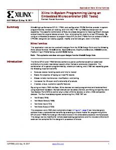
3- VIO core: This Core tool provides the ability for adding virtual inputs and outputs to an HDL designs. Virtual inputs and outputs can be synchronized to a particular clock or to be completely asynchronous with respect to any clock domain in a design. The number of input and output signals used by the VIO core can be customized as well. Figure 1 illustrates a simple ChipScope design example showing the interaction of the three mentioned cores with an FPGA design. On the PC, Chipscope software will be running to give a full visual analysis. The collected data can be exported in a variety of file formats to be used by other tools.
In this paper, the methodology for debugging an FPGA based digital design using ChipScopeTM technology is presented. The paper is organized as follows: First the main core types of the Chipscope logic analyzer will be briefly described. Secondly the specifications of the developed digital design and three examples from the debugging stages are given. Finally summary and conclusion remarks will be drawn.
356
ISSE 2006 St. Marienthal, Germany
3. FPGA BASED DIGITAL SYSTEM
SCK
The target digital design has been tested and presented as in [6] using state machine controller of a wireless sensor system. Two FPGA devices of type Spartan 3 have been employed in the design to interface both the transmitter and receiver. In this paper is focusing on debugging the transmitter FPGA design that is shown in Figure 2.
ADC
CS
4. SYSTEM DEBUGGING
ILA Core O/P
VIO
USING
CHIPSCOPETM
LOGIC ANALYZER
The components of the ChipScopeTM environment used in transmitter side FPGA1 are shown in Figure. 4. The ICON allows the user to export the data samples stored in the internal RAM of each ILA after setting the trigger conditions. The collected samples then can be sent through the JTAG connection to be displayed on a PC.
Development Board
ICON Core
FPGA
SPI Unit (FPGA)
Fig. 3. Simple Chipscope design example.
PC JTAG
Data_in
ILA probes
SPI
FPGA design
FPGARAM
ChipScope in FPGA1
ILA1
I/P Compressor
Fig. 1. Simple Chipscope design example.
FPGARAM
ILA2
ICON
JTAG
Framer
FPGARAM
Fig. 2. Transmitter side FPGA based design.
ILA3
Fig. 4. ChipScopeTM components in FPGA1
The main units of the transmitter processor are: (Serial Peripheral Interface) SPI, Memory storage (Block RAM), data compressor, and framer. The SPI unit is configured as a master, where SPI bus consists of three lines: serial clock (SCK), data sent by the ADC Data_in, and chip select (CS) as in Figure 3.
4.1. SPI debugging The SPI debugging process was facing a challenge in the implementation due to the need for creating a realistic model for the ADC. The model should provide a certain data stream when getting a stimulus signals from the SPI unit. CS is one of these two signals where a data frame transmission is initiated at the falling edge of the signal and ends on the rising edge. Each data frame must contains an integer multiple of 10 rising SCK clocks as specified for ADC
In the following section, our paper, Chipscope technology will be introduced to test the functionality of the SPI and Block RAM, which is the storage of the incoming data from SPI.
357
ISSE 2006 St. Marienthal, Germany
data_in
operation . During each conversion, the Data_in byte should be clocked into the SPI input on the first 8 rising edges of SCK after the fall of CS. To work around this issue, a stand-alone SPI unit and extra hardware have been created and tested separately first to verify the debugging methodology. The VIO core has been used for such task to behave as an ADC with the required specifications. The CS signal should be synchronized with the data coming and such functionality is not available in the VIO core. To overcome this problem, pulse train feature of the VIO has been employed with extra hardware developed to control the data flow. In Figure.5, the schematic of the logic analyzer for the SPI using Chipscope cores is given.
CS
SPI_Out
SPI Unit
ILA Data Trigger CLK
De-MUX
VIO Core Pulse train
ICON
Counter
A pulse train of 16 bits data will be sent from the VIO, which is de-multiplexed into two separated signals. The first bit here will act as chip select to enable data conversion. Initially when the first bit is 0, then do nothing or the unit will be on Idle State. When the first bit becomes 1, then CS is enabled and the counter will specify which data bit is being sent starting from bit 2 to 9. Figure.6 presents sample from Chipscope waveform results where a value of 55 has been shifted through the SPI register and captured by the ILA.
CLK
Fig. 5. ChipScope logic analyzer for the SPI unit 4.2. Block RAM debugging The Block RAM performance will be tested in the same manner as with the SPI, independently. The VIO core here will be used to generate the following input signals: •
Write enable (We)
•
Memory address (addr)
Fig. 6. ChipScope trigger and waveform window of the SPI debugging
358
ISSE 2006 St. Marienthal, Germany
•
to generate test data for the SPI and VIO2 will receive the data value from the Block RAM after triggering the ILA2. Figure.9 presents sample waveforms from the debugging process where a byte of value 55 has been used as a test data.
8 bits data samples (data_in)
The input of the VIO and the ILA will be the captured data bytes coming from the Block RAM. In Figure.7, the schematic of the logic analyzer used with the Block RAM is shown. Both cores, the ILA and the VIO are connected to an ICON core, which is communicating with Chipscope software.
data_in CS
SPI_Out
SPI Unit
ILA1 Data Trigger
data_in addr
Block RAM
We
CLK
De-MUX
data_out
ILA
VIO1 Core Pulse train
CLK
Counter data_in
VIO
ICON
addr
Block RAM
data_out
ILA2
We Chipscope
Fig. 7. ChipScope logic analyzer for the Block RAM
VIO2
unit
ICON
4.3. SPI-Block RAM debugging In this section, the functionalities of both units, SPI and Block RAM, have been verified. A test data will be read by the SPI shift registers and then sent to the Block RAM to be stored. The logic analyzer hardware is structured as in Figure. 8. As shown, VIO1 is used
Fig. 8. ChipScope logic analyzer for the SPI-Block RAM units
Fig. 9. ChipScope trigger and waveform window of the SPI- Block RAM debugging
359
ISSE 2006 St. Marienthal, Germany
The Chipscope software window is divided into three sections as shown above. The first two are representing the ILA1 unit and the one at the bottom is displaying the VIO2 values. The size of the captured samples by the ILA was set to be 128. The data value 55 has been shifted by the SPI register when CS is active low and then stored by the Block RAM after the ILA triggered (T sign).
Block RAM needed to store the captured samples in a big slot of time.
REFERENCES [1] C. Carmichael, “VIRTEX configuration and readback,” Application Note XAPP 138, Xilinx, San Jose, CA, March 1999. [2] W. H. Olfich, “Using the XC4000 readback capability,” Application Note XAPP 015, Xilinx, XC4000, SanJose, CA, 1994. [3] Lucent Technologies, Allentown, PA, ORCA Series 4 Field-Programmable Gate Arrays, December 2000. [4] Xilinx, San Jose, CA, ChipScope Software and ILA Cores User Manual, v. 1.1 ed., June 2000. [5] N.Ohba, and K. Takano, “Hardware debugging method based on signal transitions and tranactions”, IEEE Proc Asia and South Pacific conf on Design Automation, Jan 2006, pp.454-459. [6] K. Arshak, E. Jafer, and D. McDonagh, “Modeling remote system for sensor monitoring using Verilog HDL and Simulink Co simulation”, IEEE Proc Conf on Behavioral Modeling and Simulation (BMAS), Sept 2005, pp.64-69.
The VIO bottom window displays the value 55 written into the Block RAM when write signal has been enabled. The outcome of this verification process was useful for assessing overall system performance. Making sure that SPI design is functioning properly, as an interface to an external device, and the Block RAM capturing the right data was the main core of the whole system debugging. It became now an easier task to verify the rest of the system units using the same methodology.
CONCLUSIONS In the past different FPGA based designs have been implemented with serious difficulties in verifying and debugging. The ChipscipeTM technology allowed us to save the implementation time, effort and to eliminate hidden bugs. This work presented a new methodology for verifying and debugging an FPGA based system. The three Chipscope cores have been employed in this process to form the components of the logic analyzer circuit. The hardware verification method applied in this work is based on testing each unit independently before testing it again in combination with the neighbor ones. This will give more flexibility to the designer to check the functionality of each part of the system without having to re-implement the entire design. The use of VIO core was ideal for standalone unit debugging, where it can generate any necessary input stimulus signals and probes the output at the same time. Such a feature was very useful during the work to model the ADC which needed a lot of care to get the right synchronization between the input and output signals. The resources used by the ILA, ICON, and VIO in the Spartan 3 device were a few percents only. The main limitation of this technology is the size of the
360
ISSE 2006 St. Marienthal, Germany