Testing Solar Air-heating Collectors - Science Direct
Recommend Documents
aRenewable Energy System and Recycling Research Centre, Transilvania University ... Keywords: solar thermal flat plate collector; aging; saline environment; ...
This paper describes the derivation of a modified equation for solar collector efficiency that is expressed using the heating load term instead of the inlet fluid ...
neglected for solar water-heating collectors in the actual testing standard. ... also with the technical background of this curve, almost every collector around the ...
The E.C. Joint Research Centre, Ispra Establishment, was a major ...... the collector to follow the sun in azimuth using manual ...... DIN 5036/Part 3, Radiometric and Photometric ...... (e.g. stores, boiler house) incorporating the collector array.
Aug 10, 2008 - where there is an abundance of solar energy. The initial concept ... The work represents an important step toward the ultimate ... which will lead to a wide spectrum, high conversion efficiency, and low-cost solution to ...
World Solar Challenge race in 1987, beating all other competitors by 2 days. By 1996, the best ... Free up the streets for humans again and put the transportation system overhead. (Streets used to ... step backward, not an advance. (The same ...
Aug 10, 2008 - electromagnetic collector (NEC) has been designed, prototyped, and tested. Proof of concept has been validated. The NEC devices target ...
Hybrid photovoltaic/thermal (PV/T) systems provide both electrical and thermal energy. The development of seawater-proof PV/T systems can enlarge the, ...
a Graduate School of Business, Stanford University, United States b McCormick School of ... Available online 2 December
Apr 22, 2015 - Energy, experimental, photovoltaic thermal, solar. Correspondence ... This work details a methodology to characterize the performance of solar.
Solar chimney technology without solar collectors. Christos D. Papageorgiou, Michael Psalidas, Petros Katopodis. National Technical University of Athens.
Jan 13, 1981 - m where (ra) is the annual average effective transmittance- absorptance product for the pool; ..... H. D. Guberman, P. R. Barnes and A. A. Prato, Assessment of the possibility of ... Orlando, FL (1977). 6. R. Talwar, Performance ...
In this paper a survey of the various types of solar thermal collectors and ... A historical introduction into the uses of solar energy is attempted followed by a ...
5.1.5. Air Systems for Hot Water Production (Active). 5.2. Solar Space Heating and Cooling. 5.2.1. Air Systems. 5.2.2. Water Systems. 5.2.3. Heat Pump Systems.
A,J. Vdzquez et aL / Surface treatment of steels by solar energy ... In the case of solar concentrated beams we can also work at atmospheric pressure. There are ...
In this paper, detailed exergy analysis of selected thermal power systems driven by parabolic ... need to improve the performance of thermal power plants inte-.
Feb 14, 2011 - Relative to solar water heaters, solar air heaters have received relatively little investi- gation and have resulted in few commercial products.
Jan 7, 2009 - ABSTRACT: The use of solar collectors with coloured absorbers for water heating is an area of particular interest when considering their ...
INTEGRA 400/100. INTEGRA 500/140. Total capacity. 400 l. 500 l. Warm utility
water reservoir. 100 l. 140 l. Maximum pressure in the heating water reservoir.
Richardson, Texas 75080. Email:[email protected]. ABSTRACT. This paper presents a novel method of integrating Phase. Change Materials (PCMs) and ...
Jan 7, 2009 - black, water heating solar collectors is examined. Subsequently, the ..... collectors, Proceedings of the Industry Workshop of the IEA Solar Heating and Cooling. Programme, Task 26, 2001, Delft. [3] Tripanagnostopoulos, Y.
In fact, tropical conditions such as high humidity, acidic rain and ... maintenance within the new PV system designs along with some research directions to ...
8(12), 3395-3408 (2015). [4] Han Xu, âCharacterization of n-type Mono-crystalline Silicon Ingots Produced by Continuous Czochralski (Cz) Technologyâ, Energy.
gas-splitting reactions, thereby converting solar energy directly into fuel[7]. ... solid solution decomposition[5,11,12], and displacement reaction[13,14]. Undoped ...
Testing Solar Air-heating Collectors - Science Direct
standard test procedure and discusses the reasons why the tests were defined as they are. 2. Performance parameters. For marketing of solar collectors today ...
Available online at www.sciencedirect.com
ScienceDirect Energy Procedia 48 (2014) 137 – 144
SHC 2013, International Conference on Solar Heating and Cooling for Buildings and Industry September 23-25, 2013, Freiburg, Germany
Testing solar air-heating collectors Korbinian S. Kramer*, Christoph Thoma, Stefan Mehnert, Sven Fahr Fraunhofer Institute for Solar Energy System, Heidenhofstr. 2, Freiburg 79110, Germany
Selection and peer review by the scientific conference committee of SHC 2013 under responsibility of PSE AG doi:10.1016/j.egypro.2014.02.017
138
Korbinian S. Kramer et al. / Energy Procedia 48 (2014) 137 – 144
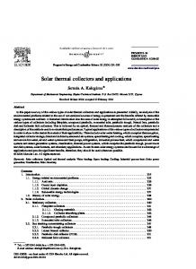
1. Introduction Solar air-heating collectors (SAHC)s are marked available in different countries around the world. In some countries a level of market penetration is reached, where different products start to be in competition with each other. In the recent re-vision of the testing standard of the International Standardization Organization (ISO), the technique of solar air heating collectors was therefore implemented in the respective collector testing standard (ISO/FDIS 9806:2013). The motivation is of course, to support a sustainable market development. For this a transparent and fair characterization and rating is helpful. Therefore the paper describes different steps of the standard test procedure and discusses the reasons why the tests were defined as they are. 2. Performance parameters For marketing of solar collectors today the efficiency parameters seem to play by far the most important role. Collectors are often described and compared by referencing the well-known efficiency curve. Beside some issues also with the technical background of this curve, almost every collector around the world is described with such an efficiency curve. Nowadays the collectors are characterized by the power output. This value is derived from measuring the efficiency of the collector and multiplying it with the collector size. These values are provided for different radiation levels as well as different temperature lifts. Especially helpful for the acceptance is the fact, that many countries base their national testing methods on the same international standards, (e.g. the European one (EN 12975-2:2006)). This is enhanced by the recent merge of the former (EN 12975-2:2006) and (ISO/FDIS 9806:2013), which harmonizes the methods in even more details. For solar air-heating collectors some aspects have to be taken into account, which might be neglected for the case of solar water heating collectors (SWHC)s. Such are the mass flow rate dependency, the “open to ambient” operating mode and in consequence of the latter the definition of the IAM (incidence angle modifier). Under the aspect of so-called “un-covered” and “covered” collectors the methodologies for performance measurement are to be differentiated in an adequate way. This differentiation actually is applied as used for SWHCs. 2.1. Collector efficiency curve The power output of the collector is determined by measuring the inlet temperature (in case of open to ambient collectors the ambient temperature) and the outlet temperature, as well as the mass flow rate. By dividing the energy gathered by the energy provided, which is the global radiation (measured in the plane of the collector) multiplied with the collector area, the power output of the collector results. Of course the power output is thereby depending on the mass flow rate, the radiation level and the temperature level. So this information has to be given surplus to the power output value, to make it a sound description of the performance. In the case of a solar air-heating collector, which heats up directly the fresh air, meaning which is operated in open to ambient mode, the operating temperature can normally hardly be varied in outdoor testing conditions. So in this case the power output is given at a single operating condition, defined by radiation, mass flow rate and temperature level. shows different influences as they have to be taken into account when presenting and describing SAHC in their performance characteristics. From this graph one can learn, that SAHC have a similar wide operating range as SWHC do. The temperature level is of course depending on the losses by convection, conduction and radiation and the conversion factor. Also it becomes clear from the experimental data that the mass flow rate has a significant influence on the heat removal and thereby the efficiency of the collector. From this point of view the mass flow rate is for the most designs to be chosen rather high. But to find the optimum mass flow rate, another aspect has to be taken into account. To generate a high mass flow rate, or better a good heat removal factor, the pressure drop (friction losses) has to be overcome by the fan, “pumping” the air flux through the collector. From the point of exergetic efficiency, the maximum reasonable mass flow rate is limited to the level, when an increase of the used energy to generate the mass flow rate is not leading to an increase of the heat output anymore. To discuss the performance characteristic of SAHC this combination of effects shall be taken into account.
139
Korbinian S. Kramer et al. / Energy Procedia 48 (2014) 137 – 144
How to define such a coefficient of performance (COP) or maybe better a seasonal performance factor (SPF), is a question of further on-going investigation. Basic work on this is recently performed by (Welz, Knecht et al. 2013). From Figure 1 the influence of wind speed dependency also becomes visible. If the absorbing layer is thermally coupled with wind, heat is withdrawn by the wind. This effect is reduced, as soon as the absorbing part (hottest part) of the collector is separated from the wind. This leads to the situation that un-covered collectors have to be described including their wind speed dependency. One can easily see from the experimental data, that by increasing the convection losses, the reducing of the conversion factor and a small shift in the mean fluid temperature to lower levels takes place. For un-covered collectors also the radiation losses, which are depending on the material of the absorber, have to be considered. At the moment this is only done by an integral approach, applying the steady state method of the standard (ISO 9806-3:1995). In a next step this can be measured applying the quasi-dynamic approach of the standard. Fraunhofer ISE is recently working on this approach. The last important characteristic to be explained is the behavior of so called open to ambient collectors. As the name already tells, these collectors are sucking in fresh ambient air, heat it up and provide it at a defined outlet. An integrated PV cell drives the also integrated fan in some of those SAHC. Such is the case for the one shown in figure 1. By a rising radiation the mass flow rate is therefore raised too. This increases the efficiency of the heat removal and at the same time reduces the provided heat level. The referenced SWHC in figure 1 gives an orientation, but the comparison of air and water based energy is only reasonable in a few operating situations. The technical potential and the systems to operate SAHC are different from the ones of SWHC. To compare SAHC and SWHC therefore seems to be not that important. More important is to compare competing technics of SAHC with each other. For this it is advisable to compare more than only the efficiency values. A system approach defining reference system boundary conditions to compare different technics within these system configurations, can be an option. At the Fraunhofer ISE C. Welz recently does extensive work on such an approach for the sake of rating (Welz, Knecht et al. 2013). 1 solar water-heating collector
0,9
0,8
SAHC @ high mass flow rate
Collec tor Efficiency [ %]
0,7 SAHC @ medium mass flow rate
0,6 0,5
SAHC @ low mass flow rate
0,4 Un-covered SAHC @ 3m/s wind and 4 mass flow rates
0,3 0,2
Un-covered SAHC @ 1.5m/s wind and 4 mass flow rates
0,1 0
0
0,01
0,02
0,03
0,04
0,05
0,06
Un-covered SAHC @ 0m/s wind and 4 mass flow rates
dT/G in Km²/W Figure 1 shows the efficiency curves, points respectively of different collector types. The empirical results are shown at different operating temperatures, flow rates and 1000 W/m2. The grey dashed line gives an example for a typical solar water-heating flat plate collector efficiency curve. The three black lines, show covered solar air-heating collector efficiency curves at different mass flow rates (dashed= low rate, doted=medium rate, continuous=high rate). The purple (= 3m/s) points show the influence of the wind speed. Again this is shown together with the mass flow rate as well as the operating temperature on an un-covered, open to ambient collector. The same is shown for 1.5m/s wind speed (blue points) and 0m/s (yellow points). The green triangle points describe the mass flow dependency of a covered, open to ambient solar airheating collector.
140
Korbinian S. Kramer et al. / Energy Procedia 48 (2014) 137 – 144
2.2. Incidence angle modifier The Incident Angle Modifier (IAM) is defined as shown in equation 1:
K hem T L , TT
K0,hem T L , TT K0,hem T L,def , TT ,def
(1)
To generate this value experimentally, the efficiency at normal radiation is measured at an operating point with the heat losses of the collector being net zero (net zero means that the same amount of heat gains from ambient is lost to the ambient because of the different temperature of the collector over its entire area). In the case of uncovered, open to ambient SAHC, in combination with a PV driven fan, the experimental boundary conditions are not possible to provide the input for equation 1. So in this case the behavior of an SAHC with changing incidence angles can be described just by giving the measured results at a specific angle. For simulations this deficit should be taken into account. Further investigations on this issue are on-going at Fraunhofer ISE. 2.3. Thermal capacity The thermal capacity of a collector describes the sum of thermal inertia of the used material in the collector. For transient collector simulation the change of radiation and its time vise consequence to the fluid outlet temperature is of relevance. Since the complete collector inertia is not completely changing its temperature with quick changes of the radiation, the partial masses of the different materials used in the collector are weight by their interference with the fluid. Meaning, the material parts, which are close coupled to the fluid, are most relevant and therefore weight with one. The insulation on the backside if not directly interfering with the fluid is weighted e.g. with 0.5 (see table 1). The representative capacity therefore is calculated by:
C
¦ p m c i
i
(2)
i
i
In addition to the materials used, it is also essential to know the capacity of the air flux itself, which is strongly dependent on its water content. Therefore the heat capacity is calculated according to VDI 4670 (VDI 4670-1). Table 1 shows the different weighing factors for the heat capacity calculation Table 1; Different weighing factors for heat capacity calculation.
component Absorber Insulation Heat transfer liquid External glazing Second glazing Third glazing Perforated glazing and glazing of front-pass collector (if present) Solid glazing on back-pass collector (if present)
pi 1 0,5 1 0,01 0,2 0,35 1 0.2
141
Korbinian S. Kramer et al. / Energy Procedia 48 (2014) 137 – 144
3. Tests on function By the so-called function test as implemented in the recent collector testing standard (ISO/FDIS 9806:2013), the collectors are exposed to operation conditions, which are to some extent worst-case situations. The tests are not meant to answer the question of lifetime prediction, e.g. for how many years or to which doses of UV radiation a collector can last or withstand respectively. The result of most of these tests is either a quantitative value describing a specific function/dysfunction, or a pass-fail decision. These tests therefore qualify basic function and reliability. The tests will be defined in EN (ISO/FDIS 9806:2013) (date of availability: 29th of October 2013). The questions of quantifying aging effects and thereby developing accelerated aging test, which will allow for lifetime assessments, is done by a different set of standards (e.g. (ISO/DIS 22975-3:2012), more to come). In the following the function and reliability tests as described for SAHC will be discussed. The test procedures are also a result of the discussions of open questions in the standardization groups and from own testing experience. 3.1. Rupture and collapse test This test is intended to determine the ability of air heating solar collectors to withstand the operating pressure levels. These are induced by the fan, the air ducts up-stream and/or downstream of the collector and the thermal expansion during operation.
3.2. High-temperature resistance This test is intended to assess rapidly whether a collector can withstand high temperature and irradiance levels without failures such as glass breakage, collapse or melting of plastic cover, melting of plastic absorber, or significant deposits occurring on the collector cover from outgassing of collector material or any other effect that possibly could lead to a reduced performance, lifetime, safety or distorted visual appearance of the collector. 3.3. Exposure The exposure test provides a low-cost reliability test sequence, providing conditions, which are likely to occur during real operation. It also allows the collector to "settle" in such a way, that subsequent qualification testss are more likely to provide repeatable and representative results. For the latter purpose a pre-exposure test sequence with approximately half the duration of the full exposure test is defined, if the performance test is not done at the end of the standard exposure phase anyway. The level of radiation and ambient temperature can be chosen by the manufacturer according to the classes in Table 2. Table 2 Climate reference conditions for exposure test as well as for external and internal thermal shock tests Climate condition Value for climate class Class C
Class B
Class A
Temperate
Sunny
Very Sunny
Global solar irradiance on collector plane during a minimum of 30 hours (or 15 hours in case of pre-exposure), G in W/m2/minimum ambient temperature, -a in °C
800/10
900/15
1000/20
Global irradiation on collector plane for exposure test during a minimum of 30 days, H in MJ/m2
420
540
600
Global irradiation on collector plane for pre-exposure sequence during a minimum of 15 days, H in MJ/m2
210
270
300
142
Korbinian S. Kramer et al. / Energy Procedia 48 (2014) 137 – 144
NOTE: Values given are minimum values for testing. The same class shall be applied for irradiance and for irradiation values respectively.
3.4. External thermal shock Collectors may from time to time be exposed to sudden rain on hot sunny days, causing a severe external thermal shock. This test is intended to assess the capability of a collector to withstand such thermal shocks without failure.
3.5. Internal thermal shock Collectors may from time to time be exposed to a sudden intake of cold heat transfer fluid on hot sunny days, causing a severe internal thermal shock, for example, after a period of shutdown, when the installation is brought back into operation, while the collector is at its stagnation temperature. This test is intended to assess the capability of a collector to withstand such thermal shocks without failure.
3.6. Rain penetration This test is applicable only for glazed collectors and is intended to assess the extent to which glazed collectors are substantially resistant to rain penetration. They shall normally not permit the entry of either free-falling rain or driving rain. Collectors may have ventilation holes and drain holes, but these shall not permit the entry of drifting rain. Humidity in the collector is thereby not a fail per se. Important is, that the humidity is vanishing in a reasonable time after the rain stopped, and no damage is remaining from this. 3.7. Mechanical load The mechanical load test with positive pressure is intended to assess the extent to which the transparent cover of the collector, the collector box and the fixings are able to resist the positive pressure load due to the effect of wind and snow. The mechanical load test with negative pressure is intended to assess the deformation and the extent to which the collector box and the fixings between the collector cover, collector box and collector mounting are able to resist uplift forces caused by the wind. 3.8. Impact resistance This test is intended to assess the extent to which a collector can withstand the effects of impacts caused by hailstones, or dropping parts during installation. 3.9. Stagnation temperature The result of this test is to derive information on the maximum temperature to be expected occurring in the collector under conditions of stagnation (no heat removal). The result is given in steps of ten degree Celsius based on the information provided by the manufacturer, in combination with a plausibility check.
Korbinian S. Kramer et al. / Energy Procedia 48 (2014) 137 – 144
143
3.10. Maximum start temperature This test determines the maximum outlet temperature of the air after a (re-)start from stagnation. This information is useful for the design of all components installed downstream the collector.
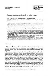
3.11. Leakages rate determination The test is intended to quantify the volumetric leakage flow rate of SAHCs. In some cases of collector designs the leakage test is not applicable (e.g. collectors operating only open to ambient, without defined in- and outlet).
Figure 2 shows typical leakage rate distribution from negative internal pressure to positive internal pressure. (1 = volumetric leakage flow rate in m³/h, 2 = collector pressure in Pa).
3.12. Pressure drop The pressure drop of a collector is a value for frictions losses occurring during the flow through the fluid channels. The pressure drop depends on the mass flow rate. It is an important value for dimensioning the fan and other componensts within the air duct system. From this value together with the efficiency of the fan the parasitic electrical energy demand can be derived.
3.13. Final inspection When the tests have been completed, and the same collector is not going to be used for the performance test, the collector used for the function tests shall be dismantled and inspected. All abnormalities shall be documented and accompanied by photographs. The collector and all of its components shall be described and should be photographed (glazing, absorber, absorber coating, insulation, housing, inlet and outlet ports, glazing supports and retainers, seals, gaskets, back sheet, etc.). 4. Conclusion and outlook Within the last three years the set up for an equivalent characterization of SAHC and SWHC has been developed by the Fraunhofer ISE TestLab Solar Thermal Systems and other international test labs. The scope of the revised
144
Korbinian S. Kramer et al. / Energy Procedia 48 (2014) 137 – 144
testing standards was enlarged respectively by the corresponding international standardization groups and bodies. The merge of former EN and ISO testing standards to EN ISO 9806:2013 opens up the application of the standard to a more global perspective. This helps to reduce trading barriers and developing sustainable markets. The characterization also provides transparency for the decision makers (e.g. end consumers, policy makers) as well as for manufacturers. Different technical variations can be compared and a benchmark can be defined. Based on the tests a certification is easily possible as it will be the case e.g. for the Solar Keymark certification. For planners the information provided in a standardized and comparable way also opens the possibility of more detailed calculations on energy savings using SAHC. However, some issues that are more specific characteristic of SAHC remain to be investigated in detail and incorporated in standardization, rating and certification. In particular, the quasi-dynamic method should be validated and adapted for SAHC in the coming years. Surplus to this the mass flow dependency should be included in the equation explicitly. The complete sector of SAHC – System qualification is also in the focus of Fraunhofer ISE. References [1] EN 12975-2:2006 Thermal Solar Systems And Components - Solar Collectors - Part 2: Test Methods [2] ISO 9806-3:1995 Thermal performance of unglazed liquid heating collectors (sensible heat transfer only) including pressure drop. [3] ISO/DIS 22975-3:2012 Solar Energy-Collector components and materials -- Part 3: Absorber surface durability. Document stage: Draft. [4] ISO/FDIS 9806:2013 Solarenergy - Solarthermal collectors - Test methods. Document stage: Final draft. [5] VDI 4670-1 Thermodynamische Stoffwerte von feuchter Luft und Verbrennungsgasen, Ausgabe 2003-02. [6] Welz, C., M. Knecht, et al. (2013). Thermohydraulische Simulation von Luftkollektorsystemen und Systembezogene Bewertung von Luftkollektoren. Thermische Solarenergie / 23. Symposium, April 24-26. O. e.V. Kloster Banz, Bad Staffelstein, Germay, Ostbayerisches Technologie-Transfer-Institut / Bereich Erneuerbare Energien (OTTI): noch nicht bekannt.