Testing Systems Wirelessly Hans Eberle Sun Microsystems Laboratories
[email protected]
Arvinderpal Wander University of Michigan, Ann Arbor
[email protected]
Nils Gura Sun Microsystems Laboratories
[email protected] Abstract Wired test structures exhibit many unwanted dependencies: They typically use hierarchical and daisy-chained wiring, and they share interconnects and backplanes with the system under test. As a result, faults can easily lead to incomplete or erroneous test reports on properly working components. Wireless test structures do not have these shortcomings and, thus, allow for more accurate testing and diagnosing. Wireless communication further allows for non-intrusive testing that does not require any cabling or physical access to the system under test. We describe two prototype implementations: a wireless field-replaceable unit ID and a wireless version of the popular JTAG standard.
1. Introduction Replacing wired test structures with wireless test structures offers many advantages. Most importantly, by using a communication infrastructure that is orthogonal to the one used for regular system operation, the testee and the tester are completely decoupled. Otherwise, if, for example, wired test structures share connectors and backplanes with the system under test, a fault of a shared component easily affects the accuracy of the test results. Being a broadcast medium, wireless communication further removes dependencies found in wired interconnects that use hierarchical wiring and daisy chains. Thus, faults cannot affect properly working components and lead to misdiagnosis referred to as No Trouble Found (NTF). We are currently observing a proliferation of radio technologies. Particularly interesting for the work described here is the emergence of low-cost wireless networks such as ZigBee [10] and IEEE 802.15 WPAN [3] that address remote monitoring, control and sensory network applications.
In this paper, we describe two prototype implementations that demonstrate the applicability of a wireless test structure. We first describe the wireless field-replaceable unit ID (FRUID) which is an identification tag for fieldreplaceable units. Next, we describe a wireless version of the popular JTAG standard.
2. Wireless communication for out-of-band signaling In the following section, we list the many advantages offered by wireless communication.
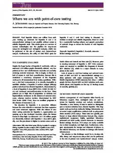
2.1. Direct communication Wireless communication provides a direct connection between a tester and a testee. There are no indirections that are, for example, found in systems that use daisy-chained or hierarchical wiring. In these systems, a failure of an intermediate node makes any dependent node inaccessible thereby preventing the system controller from determining the state of all components. An example of a scan path such as JTAG [4] using traditional wiring techniques is shown in Figure 1a and an alternative design using wireless communication is shown in Figure 1b. The wired scan paths connecting the chips on a daughter card are linked serially in the form of a daisy chain. A bridge on the mother board connects the daisy chains of the daughter cards. A large system might employ additional levels of hierarchy (not shown) in that the daisy chains are connected in a tree-like structure where the daisy chains are the leaves and the bridges are the nodes. Such a topology contains many unwanted dependencies. Figure 2 illustrates examples of possible failure scenarios caused by these dependencies: • If a failure of a chip on the daughter card breaks the daisy chain, all chips that come later in the chain be-
Figure 1. Wired (a) and wireless (b) scan paths.
come inaccessible even though they might be fully functional (Figure 2a). • Assuming a hierarchy of bridges, a failure of a bridge causes the corresponding sub-tree to become inaccessible even though the nodes and leaves of the sub-tree might be fully functional (Figure 2b). • System availability can be improved by employing redundancy. Still, if components and wires are simply replicated, as is standard practice today, we can expect similarities in failure behavior.
2.2. Non-intrusiveness Wireless communication is non-intrusive since it does not rely on any physical cabling. Thus, it is a particularly attractive alternative for any task that requires a physical communication link to be temporarily connected to the system. Connecting cables typically requires manual intervention which can be error-prone and time-consuming. Wireless communication removes these shortcomings. Moreover, it offers an efficient way to automate these tasks.
2.3. Reliability Physical interconnect technologies using cables and connectors are inherently unreliable. Causes are manifold: wires are improperly connected in the first place or become loose through wear and tear, while connectors and their contacts become corroded and worn. Thus, a wireless interconnect offers higher reliability than a physical interconnect.
Figure 2. Failure scenarios for daisychained and hierarchical wiring: chip (a) and mux/demux (b) failures.
2.4. Cost Radio communication has the potential to reduce system cost since it does not require a physical interconnect based on wires and connectors.
3. Wireless FRUIDs To ease repair and upgrade of system components, high-end computer systems are commonly modularized into field-replaceable units (FRUs). By subdividing systems into FRUs, components can be replaced by a technician or a user in the field without requiring the costly replacement of the entire system. Also, fewer parts are replaced thus reducing the cost of the replacement hardware. More importantly, system downtime is minimized. System availability can be further improved by allowing for hot-pluggable and redundant FRUs. To help with maintaining system information, FRUs are equipped with FRUIDs that store information on the FRU. A FRUID is implemented with a nonvolatile memory such as an EEPROM. Typical capacities of FRUID memories
are in the order of 8 kbyte. This information can be used to determine the characteristics and the state of the FRU. FRUIDs contain static data written at manufacturing time and dynamic data updated over the course of the FRU’s lifetime. Examples of static data are manufacturing information and FRU specifications. Examples of dynamic data are revision history or log files reporting sensor readings or captured error reports. FRUID technology is currently employed mostly in high-end server systems. The technology is, for example, used by the Intelligent Platform Management Interface (IPMI) [5] to manage modular system platforms. Wireless FRUIDs offer many advantages. They improve serviceability by removing the dependencies of a wired interconnect described in Section 1. Traditionally, the wiring used to interconnect FRUIDs resembles a tree with hierarchical wiring used higher up the tree and daisy-chains used to connect the leaf nodes. As explained before, faulty segments in such an interconnect can easily affect nodes that are fully functional in that they become unreachable. As a result, unreachable nodes are reported as malfunctioning causing a technician to replace a FRU that is not broken. This incident is known as no trouble found (NTF) - it refers to the replacement of a fully functional FRU that was mistakenly diagnosed as faulty. Wireless FRUIDs also make it easier to access FRUIDs as no wiring and no cabling is required. We will later describe an application scenario where a field technician accesses FRUID information through a wireless PDA. Wireless FRUIDs further enable new applications such as advanced tracking. Systems need to be tracked all along the way from the manufacturing floor to the customer’s premises. Systems are typically built to order. To verify that a system is assembled according to the customer’s specifications, manufacturers scan the identity of the system modules using bar codes. With wireless FRUIDs, this process can be simplified in that the configuration can be determined wirelessly without requiring an optically readable bar code and a line of sight between the bar code and the reader. Wireless FRUIDs also automate inventory tracking at the customers’ premises. The data gathered through the wireless FRUIDs can be used to maintain the inventory database of the customer as well as of the field service organization. Having accurate and current information on the FRUs simplifies system maintenance and administration. For example, compatibility conflicts can be easily determined knowing the exact revision history of all FRUs. There are similarities between wireless FRUIDs and RFID tags [9]. RFID tags are, however, less capable in that they only store a small amount of static data - the memory capacity today is 96 bits. This data is stored at manufacturing time and cannot be updated. Further, RFID tags are
Figure 3. Non-intrusive testing in the field.
passive, that is, they can only transmit data when powered by the electro-magnetic field generated by an RFID reader, whereas wireless FRUIDs can initiate transfers, for example, to report on changes of their dynamic data contents. While the testing and tracking capabilities described here mostly apply to today’s high-end systems used by enterprise and scientific users, we can expect that, thanks to commodization, similar capabilities will eventually be incorporated into low-end and high-volume systems.
3.1. Application scenarios We describe two possible application scenarios. A first one describes wireless diagnostics in the field and a second one extends this usage model to include remote diagnostics. Fig. 3 shows a computer rack that houses FRUs equipped with wireless FRUIDs. The FRUIDs are accessed by a wireless PDA, for example, used by a field technician to diagnose a malfunctioning system. Without having to connect any probes, cables, or terminals, the technician obtains the information from the wireless FRUIDs that allows him to determine the configuration and the state of the system. Coupled with the appropriate database, the PDA can also display the service history of each FRU. Fig. 4 extends this scenario in that wireless FRUIDs are used for permanent monitoring of an entire data center from a remote location. This is accomplished by adding a bridge to each rack that relays the FRUID information to a wireless network such as a cellular phone network or a WiFi network. This network, in turn, connects to the Internet such that the FRUID information is ultimately accessible over the Internet.
3.2. Prototype implementation We have implemented a prototype of a wireless FRUID to demonstrate its feasibility and to showcase non-intrusive diagnostics. More specifically, we have built a prototype of the application scenario shown in Fig. 3 where a PDA accesses FRUIDs by wireless communication.
Figure 5. Block diagram of the wireless FRUID prototype. Figure 4. Remote diagnostics.
Fig. 5 gives a block diagram of the prototype. We use a Palm III PDA (master) that is equipped with a wireless gateway to communicate with the FRUID (slave). The FRUID is located on a system motherboard of a desktop system. The FRUID has been modified so that it now has two ports: There is a regular wire interface to provide backwards compatibility and, in addition, there is a radio port so that FRUID data can also be accessed wirelessly. We built the radio module shown in Fig. 6 that can be used for both the slave and master side. That is, the module adds a radio port to the FRUID, and it serves as the wireless gateway for the PDA. The module uses the CC1010 system-on-a-chip from Chipcon AS [1]. This chip combines an industry-standard 8051 8-bit microcontroller with a 300 - 1000 MHz RF transceiver. The RF transceiver uses FSK modulation and provides data rates up to 77 kbit/s. As can been seen in Fig. 6, the antenna is implemented as a dipole antenna using board traces. We operate the RF transceiver in the license-free 868 MHz band. Given the short range of the radio signal, power consumption is relatively low: The RF receiver consumes 12 mA and the RF transmitter consumes 17 mA at 1 mW transmitted power. The RF transceiver is designed for multi-channel and frequency hopping applications. This feature can be useful to bypass channels blocked by a faulty transceiver or rendered unusable due to interference. The module is used as follows. On the FRU, the module is interfaced with the serial EEPROM, creating a wireless FRUID. The data contained in the FRUID is replicated in the flash memory of the microcontroller. A snooping protocol that monitors the write operations on the interconnect between the FRU and FRUID is used to keep data in both the flash memory and the FRUID consistent. When FRUID
data is requested via the radio port, it is retrieved from the microcontroller’s flash memory. By maintaining two separate copies of the FRUID data, simultaneous accesses to the FRUID through the wired interface and the radio port cannot conflict. On the PDA side, the module acts as a wireless gateway by relaying packets between the wireless FRUID and the serial port of the PDA. The PDA can then be used to query and display FRUID data such as manufacturing records, diagnostic information, etc. We currently use a simple request/acknowledge protocol. All data transfers are initiated by the master. We plan to extend the protocol such that a transfer can also be initiated by a slave, for example, to alert the master of an error condition.
4. Wireless JTAG The JTAG standard [4] is a serial interconnect that adds testing capabilities to system components and, in particular, to integrated circuits. JTAG is primarily intended for performing boundary scan tests that test the logic internal to the component as well as the connectivity external to the component with respect to other components. Furthermore, JTAG interfaces are widely used to configure components such as CPUs, nonvolatile memories, and FPGAs. A wireless version of the JTAG standard offers many advantages and opportunities. Most importantly, it removes the dependencies of wired interconnects that we described in Section 1. Daisy-chained wiring typically interconnects the JTAG ports of the components on a system board. And hierarchical wiring in the form of multiplexers and demultiplexers connects the boards. Not only does radio communication remove these dependencies that may lead to NTF, it also breaks the possibly long shift register formed by the
Figure 7. Block diagram of the wireless JTAG port for DIMMs.
Figure 6. Prototype of the radio module for wireless FRUIDs.
daisy-chained JTAG registers by giving selective access to each JTAG port. For large high-end systems, it can easily take several minutes to read out this shift register. When diagnosing systems, this time is added to the mean time to repair (MTTR) which is a critical parameter of a system optimized for reliability, availability, and serviceability (RAS). Wireless JTAG ports, in contrast, can be accessed directly allowing for selectively accessing FRUID information. Thereby, the MTTR can potentially be significantly reduced. Wireless JTAG further offers non-intrusive operation in that no cables and no probes need to be attached thereby offering non-intrusive testing, debugging, and configuration. For example, with wireless JTAG, EEPROMs or FPGAs can be reprogrammed wirelessly without having to connect the programmer with the device to be programmed. Wireless links pose limitations on transmission rates. Low-cost radio transceivers as used for our prototypes provide data rates up to 100 kbit/s and, therefore, could not be used for some of the high-bandwidth JTAG applications that require data rates in the MB/s range. Though radio technologies such as 802.11g exist that provide much higher data rates, there are no low-cost implementations currently available with comparable performance. We have built a prototype of a wireless JTAG interface 1 for dual inline memory modules (DIMMs). Here, we give a brief description only, more details can be found in [2]. A block diagram and picture of the prototype card are shown in Figures 7 and 8, respectively. The system is implemented as an extender card that plugs into a DIMM socket of a motherboard on one side and connects to a regular 1
We are loosely using the term JTAG as the prototype does not interface a true JTAG port to a radio link.
DIMM card on the other side. The extender card contains a field-programmable gate array (FPGA), a microcontroller, a radio transceiver, and a three-port crosspoint switch connecting the motherboard, DIMM, and the FPGA. The extender card provides the following functions through the wireless JTAG interface: 1. Measure the voltages and temperatures provided by on-board sensors. 2. Read the serial presence detect (SPD) [6] on the DIMM which contains the parameters specifying the DRAM chips and the organization of the DIMM. 3. Perform a self-test of the DIMM. Tests consist of writing data patterns into memory locations and subsequently reading data back from these locations and checking the obtained data values. 4. Perform a test of the interconnect. This test involves two extender cards, one writing a test vector to the memory bus and another one reading the signal values back from the memory bus. By comparing the vectors that were written and read, the wiring and connectors of the DIMMs and the motherboard can be checked for open and shorted connections.
5. Future work The prototypes described in this paper were built as a proof of the concept of testing systems wirelessly. More work is required in the areas of electro-magnetic interference (EMI), chip integration, and security. While we have successfully demonstrated the operation of our prototypes in running computer systems, more elaborate EMI testing needs to be conducted. A preliminary spectrum analysis has shown that the emitted energy of the radio transceivers used is significantly below other sources of EM fields. Still, we need to quantify interference between
Figure 8. Prototype of the wireless JTAG port for DIMMs.
the wireless test structures and the system under test. Also, we need to explore alternative radio modulation techniques and their robustness to interference. We used off-the shelf components for implementing the prototypes since our main goal was to demonstrate the concept of a wireless test structure. To productize these applications, implementation cost needed to be lowered by providing more highly integrated implementations. Ideally, the radio transceiver and the associated control logic is integrated into existing system components. In the case of the wireless FRUID, a single chip includes the FRUID memory as well as the radio transceiver and the necessary control logic. Similarly, the wireless JTAG port is integrated into a system component such as a CPU, memory chip, or a JTAG concentrator. Using wireless technology in computer systems comes with a number of inherent security risks. These risks are of particular importance for high-end server systems commonly found in data centers. Wireless broadcasts of configuration and maintenance data can potentially be intercepted. The obtained information on system components and state might not only be confidential, but could also be exploited to launch attacks. Furthermore, forged error reports could be injected into the wireless monitoring network potentially leading to system malfunction. Even worse, unauthorized write access to wireless ports would provide the opportunity to maliciously disable or misconfigure systems. To limit access to authorized users and to protect the privacy, authenticity, and integrity of the transmitted test data, a security protocol is required. There are a number of standardized security protocols to address these issues, but few attempts have been made so far to scale these solutions down to small devices with limited capabilities [8, 7].
6. Conclusions A wireless test structure offers many advantages over a wired test structure as it is orthogonal to the communica-
tion infrastructure of the system under test and as it removes the dependencies found in traditional wired interconnects. Thus, the system state can be reported more accurately improving test and diagnosis results. Wireless test structures not only improve the RAS features of a system, they also enable new applications. Wireless communication allows for non-intrusive testing. That is, no wired connections including cabling and connectors are needed between a tester and a testee. Non-intrusive operation is not only attractive for testing purposes, it also simplifies the configuration of system components. In addition to testing proposes, the wireless communication channel can also be used for wireless tracking. Examples of applications benefiting from this capability are configuration management for build-to-order manufacturing and inventory control. We have successfully demonstrated the feasibility of wireless test structures by prototyping a wireless FRUID and a wireless JTAG port for DIMMs.
Acknowledgment Keith Hargrove helped with building and debugging the prototype of the wireless FRUID.
References [1] Chipcon AS. CC1010 - single chip very low power RF transceiver with 8051-compatible microcontroller, June 2003. www.chipcon.com. [2] H. Eberle. Radioport: A radio network for monitoring and diagnosing computer systems. Sun Microsystems Laboratories Technical Report SMLI TR-2002-117, Oct. 2002. http://research.sun.com/techrep/2002/abstract-117.html. [3] IEEE 802.15 Task Group 4. IEEE 802.15 WPAN, Nov. 1996. http://grouper.ieee.org/groups/802/15/. [4] IEEE Standards Committee. IEEE standard test access port and boundary-scan architecture, July 1990. IEEE Std 1149.1-1990, IEEE, 345 East 47th Street, New York, NY 10017-2394. [5] Intel Corporation. Intelligent platform management interface. http://www.intel.com/design/servers/ipmi/ipmi.htm. [6] JEDEC Solid State Technology Association. Serial presence detect standard. http://www.jedec.org. [7] C. Karlof, N. Sastry, and D. Wagner. TinySEC: Link layer encryption for tiny devices. http://www.cs.berkeley.edu/ nks/tinysec/. [8] S. Kumar, M. Girimondo, A. Weimerskirch, C. Paar, A. Patel, and A. Wander. Embedded end-to-end wireless security with ECDH key exchange. In The 46th IEEE Midwest Symposium On Circuits and Systems, Dec. 2003. Cairo, Egypt. [9] S. Sarma, D. Brock, and D. Engels. Radio-frequency identification and the electronic product code. IEEE Micro, pages 50–54, Nov.-Dec. 2001. [10] ZigBee Alliance. www.zigbee.org.