EUROPEAN ORGANIZATION FOR NUCLEAR RESEARCH European Laboratory for Particle Physics
LHC Project Report 282
Large Hadron Collider Project
Tests Results on the First 13 kA Prototype HTS Leads for the LHC A. Ballarino and L. Serio
Abstract Prototypes of 13 kA HTS current leads for the Large Hadron Collider (LHC) have been specified by CERN and produced by several manufacturers. The specification defines the required thermo-electric performance and the geometric limitations imposed by the LHC infrastructure. A report is given of the results obtained from extensive tests on these leads.
LHC Division
Presented at the 1999 Particle Accelerator Conference, March 29 – April 2, 1999, New York, USA
Administrative Secretariat LHC Division CERN CH - 1211 Geneva 23 Switzerland Geneva, 23 April 1999
2
TEST RESULTS ON THE FIRST 13 kA PROTOTYPE HTS LEADS FOR THE LHC A. Ballarino#, L. Serio, CERN, Geneva, Switzerland Abstract Prototypes of 13 kA HTS current leads for the Large Hadron Collider (LHC) have been specified by CERN and produced by several manufacturers. The specification defines the required thermo-electric performance and the geometric limitations imposed by the LHC infrastructure. A report is given of the results obtained from extensive tests on these leads.
1 INTRODUCTION Following encouraging test results on High Temperature Superconducting (HTS) samples [1] and theoretical studies [2], a technical specification has been issued by CERN for the design and fabrication of 13 kA HTS prototype leads. Several companies have been selected for the manufacture of pairs of leads of different design. Different types of HTS materials (YBCO 123, BSCCO 2212, BSCCO 2223) have been proposed, both in bulk (MCP cylinders, MT bars) and in metal-stabilised form (PIT tapes, AFM and DIP bars). This report presents the test results of the first prototypes delivered to CERN.
2 TEST SET UP A cryostat has been built at CERN to test the thermoelectric performance of the prototype leads [3]. The helium flow (20 K, 1.3 bar), needed for the cooling of the resistive heat exchanger, is obtained by mixing of room temperature helium gas and gas vaporised from the 4.5 K liquid helium bath. The cold end of the HTS dips into 4.5 K saturated liquid helium. The vapour generated by the lead at 4.5 K cools the HTS element prior being released into the cryostat environment. The leads are tested in pairs, with a low-temperature superconducting short at the cold end. The instrumentation (temperature probes and voltage taps) is installed on the leads by the companies according to the CERN specification. Voltages, temperatures and current are recorded by a data acquisition system built with LabVIEW. The same system is used for the control of the power converter and for the simulation of the exponential decay of the current. The cryogenic parameters are controlled by an industrial PLC with an operator interface based on PCVUE32. Signals interlocked to the power supply are the voltage across the resistive heat exchanger, the voltage across the superconducting circuit and the liquid helium level. _______________________ #
Email:
[email protected]
Preprint of paper presented at PAC ’99
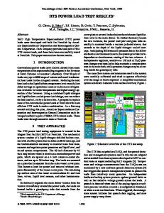
Figure 1: pair of 13 kA prototype leads on the test stand
3 TEST RESULTS Measurements have been performed in stand-by (I=0 A) and in nominal operation (I=13 kA). The leads are optimised for operating at 13 kA with the minimum 20 K helium flow (m) which maintains the warm end of the superconductor at temperatures (Tx) below 50 K. The flow is controlled by a warm valve at the outlet of the resistive heat exchanger. The temperature is read via a platinum sensor located inside the warm end cap of the HTS element. In stand-by operation, the flow is reduced and Tx is kept equal to the value in nominal operation. The temperature at the warm end of the lead is maintained at about 290 K by a heater, thermostatically controlled, included at the warm terminal of the resistive heat exchanger. The specified values defining the thermo-electric performance of the leads have been previously presented [4], [5]. Measurements have been performed in transient operation in order to study the lead behaviour in case of:
3 • loss of the 20 K helium flow cooling the resistive part of the lead; • resistive transition of the superconducting part of the lead. For the first test in operating conditions (I=13 kA, Tx≤50 K), the valve supplying the 20 K helium flow to the leads is closed and, within 5 seconds from the detection of the coolant loss, the current is made to decay exponentially with a time constant of 120 seconds. During the discharge, the temperature at the warm end of the HTS element must stay below its critical value. For the second test, the temperature at the warm end of the superconductor is brought to its critical value by increasing, at nominal current, the inlet temperature of the gas cooling the resistive heat exchanger. The resistive heat exchanger is over cooled and the voltage drop is kept equal to about the value in nominal operation. The quench detection signal is the voltage drop across the HTS element. When it reaches the critical value, indicating a resistive transition of the superconductor, the current is made to decay exponentially with a time constant of 120 seconds. The current is by-passed in a metallic shunt, included in the HTS element to protect the superconductor. The resulting ohmic heating must not damage or modify the properties of any part of the lead.
3.1 BSCCO 2223 Ag/Au tapes The first pair of 13 kA prototype leads were supplied by Fuji Electric. The resistive part consists of a CIC copper heat exchanger, while the HTS element is made with BSCCO 2223 Ag/Au tapes produced by Sumitomo [6]. At zero current, the leads were operated with the mass flow required to maintain the warm end of the superconductor at 30 K and 40 K, which is equal for both leads and corresponds to respectively 0.32 g/s and 0.27 g/s. The heat conducted by the HTS element into the liquid helium (Q) is 0.5 W, for Tx=30 K, and 0.64 W, for Tx=40 K. The current was increased from 0 to 13 kA with a maximum ramp rate of 50 A/s. At 13 kA, the steady state mass flow required to cool the resistive heat exchanger between 40 K and 300 K corresponds to 1.12 g/s for lead A and 0.97 g/s for lead B. The measured pressure drop is 16 mbar for lead A and 19 mbar for lead B. The voltage drop across the resistive heat exchanger (U) is 99.5 mV for lead A and 84 mV for lead B. At nominal current, each lead dissipates 0.715 W into the liquid helium. This value corresponds to the sum of the heat conduction plus the Joule dissipation at 4.5 K due to the contact resistance (RC) between the high temperature superconductor and the cold end cap. The contact resistance at 40 K between the warm end cap and the high temperature superconductor (RH) is about 1.15 nΩ.
Both leads were able to withstand the test of coolant loss without suffering damage. During the transient, Tx has increased from 40 K to 60 K. To perform the quench test of the HTS material, the quench detection voltage was increased in steps of 1 mV from 1 to 5 mV. For voltages below 5 mV, the voltage across the high temperature superconductor decreases as soon as the quench is detected and the current starts to decay: the resistive zone does not propagate and the material recovers the superconducting state. For a quench detection voltage of 5 mV, corresponding to a temperature (TQ) of about 86 K, the resistive zone propagates and the voltage increases up to a peak (UQ) of 0.1 V for lead A and 0.11 V for lead B. The maximum temperature measured on the HTS during the transition is about 110 K. The total energy deposition corresponds to about 0.13 MJ. In Fig. 2 is represented the time dependence of the voltage across the HTS element and of the current during the resistive transition of the superconductor. The two leads presented a comparable behaviour. The critical temperature remained the same throughout the exercise. After the quench tests, the leads have shown no deterioration in their properties. The results of the measurements on the leads are summarised in Table 1. The leads withstood the electrical insulation test performed by applying 3.5 kV between the current carrying part and the ground, in helium gas atmosphere (300 K, 1.3 bar). The leakage current measured is less than 3.5 µA, corresponding to an insulation resistance of better than 1 GΩ. Table 1: Measurements on Fuji prototype leads
Tx m ∆p Q
(K) (g/s) (mbar) (W)
Tx m ∆p U RH RC Q TQ UQ
(K) (g/s) (mbar) (V) (nΩ) (nΩ) (W) (K) (V)
LEAD A I=0 A 40 0.27±0.01 2.5±1 0.64±0.04 I=13 kA 40 1.12±0.01 16±1 0.099 1.15 0.5 0.715±0.04 86.9 0.1
LEAD B I=0 A 40 0.27±0.01 2.5±1 0.64±0.04 I=13 kA 40 0.98±0.01 19±1 0.084 1.15 0.7 0.715±0.04 86.3 0.11
4 Figure 2: resistive transition on 13 kA Fuji HTS leads 0.12
14000
0.1
12000 I
Voltage (V)
8000 V
0.06
6000 0.04
4000
0.02
Current (A)
10000
0.08
2000
5 mV
0
0 0
100
200
300
400
500
time (s)
3.2 BSCCO 2212 DIP bars A pair of 13 kA prototype leads has been supplied by Oxford Instruments. The HTS section consists of bars made up of dip coated BSCCO 2212 produced by OST. At zero current, the leads operated with a flow of about 0.19 g/s. The temperature at the warm end of the superconductor is about 30 K. The heat conduction into the liquid helium corresponds to about 1.1 W/lead. The measurements with current have been performed at 10 kA: at higher current rates, a high contact resistance, on the resistive heat exchanger of one lead, was spoiling the thermal performance. At 10 kA each lead requires about 0.79 g/s of 20 K helium flow when Tx is equal to 48 K, and about 1.2 g/s when Tx is equal to 40 K. The measured heat conducted into the liquid helium, when Tx is 40 K, is about 1.82 W/lead. The leads could withstand the coolant loss test according to specification. Quench measurements have been performed by increasing the quench detection voltage on the HTS element from 1 to 50 mV in steps of 5 mV. In all the tests, the voltage decreases as soon as a quench is detected and the current starts to decay. At 50 mV, the temperature at the warm end of the superconductor is 90 K. The maximum temperature measured is 94.7 K. No propagation of the resistive length has been measured. The results of the tests are promising. Measurements up to 13 kA will be performed after repair of the resistive joint.
3.3 BSCCO 2223 AFM bars A pair of 13 kA prototype leads has been supplied by Enel in collaboration with Cryogenic Ltd. The resistive heat exchanger consists of brass tubes. The HTS element is an assembly of Ag/Au AFM bars produced by Enel [7]. The results of the measurements are presented in Table 2. The leads could withstand the coolant loss tests. During the transient, Tx has increased from 40 K to about 60 K. Quench measurements are in progress.
Table 2: Preliminary measurements Enel/Cryogenic prototype leads
Tx m ∆p Q
(K) (g/s) (mbar) (W)
Tx m ∆p U RH RC Q
(K) (g/s) (mbar) (V) (nΩ) (nΩ) (W)
LEAD A I=0 A 40 0.27