organizational structure diagram, an entity-relationship diagram (ERD) (see
Figure 8) and data-flow diagrams. (DFDs). Each of these diagrams is composed
of ...
COMFUTINGPRACTICES Edgar H. Sibley Panei’ Editor
A single adaptable user interface (AUl) which allows the user to switch between any number of different dialogue modes at any time-even in the middle of a command-can be useful to a variety of users who are neither beginners nor experts. It can also be used in applications where different dialogue modes are appropriate for the various parameters of a single command. An implemented user interface management system (cl//WS) suggests the practicality of AMs and their automatic generation.
The Adaptable User Interface Eliezer Kantorowitz
and Odecl Sudarsky
THE AU1 CONCEP? Software systems interact with users in a large variety of ways (dialogue modes). These methods may be classified as the menu-type and the command-language-type. In a menu-type-dialogue mode (MM), the user controls the system solely through the selection of options from a number of choices presented. It is assumed that only choices that make sense are presented to the user, and that it is, therefore, not possible to select options that are not permitted. In a command-language-type dialogue mode (CLM), the user controls the system by instructions given in a certain command language. The user must know this language in order to use the system. In contr.ast with an MM, where the user is guided by menu.s and can only enter legal choices, the user of a CLM may enter erroneous instructions. A CLM should, therefore, be designed to detect improperly formulated instructions and to correctly recover from their effects. The advantages of an MM over a CLM are well known. Since the users do not have to learn any command language, they may become productive with a new system after a very short time. A new user may explore the operations provided by a system simply by browsing through the menus. If such a system also provides adequate help for every menu option, the user may operate the system without ever needing a manual. Menu systems may, however, be less satisfactory for frequent users who have to work through a large number of menus to get their work done. Waiting for a menu to appear on the screen, finding the right menu entry, and making the selection can take time. Proficient users who do not need guidance tend to prefer a concise CLM where a few keystrokes, entered at full typing speed, achieve the same effect as a numThis research was supported by the Gutwirth Fellowship Fund and by the Nicholas M. and Gisela Deutch Fellowship in memory of their martyred parents and families. 0 1989 ACM
1352
OOOI-0782/89/1100-1352
Communications of the ACM
$1.50
ber of relatively slow menu selections. Isaki and Schneidermann observed in [i’] that “Knowl.edgeable users often remark that they would prefer to type commands and believe that they can work more rapidly by just typing commands.” Realizing the different needs of beginners and experts, many systems provide two distinct user interfaces: a menu interface and a command-language interface. In these systems, the user has to select in advance (in the beginning of the session or before each command) one of these two interfaces that is best suited to the task. If a user wants to change the dialogue mode, the current command must be completed fi:rst, and then the user must request that the system switch to the desired user interface. There are cases, .however, when it is useful to change the dialogue mode in the middle of a command. To demonstrate this, we will employ an example command for drawing a black box with the lower left corner at (0,O) and the upper right corner at (1,l): BOXBLACK(O,O)
(1,l)
The first case to be discussed is that of a user who is neither a beginner nor an expert but is somewhere between these two extremes. Such a user may realize that he or she has forgotten some command language element while in the middle of composing a command and may need the assistance of menus [3, 511..Assume that the user has typed the word BOX of the example command and is uncertain about what colors are available. Shifting to an MM will facilitate color selection from a menu. A similar situation occurs when the user has made a mistake, e.g., entered a color that does not exist. After reading the error message, the user can switch to a menu of colors in order to select an available color. The need to assist users who cannot complete a command is realized in current systems, which enable commands to be programmed such that users are prompted for missing parameters. These systems, however, do not
November 1989
Volume 3.2 Number 11
Computing Practices
atom of the command language. For example, in the GUIDE system, to be described later, CLM tokens are represented by character strings. Each token may be entered in any one of the available dialogue modes, independent of the modes employed for the other tokens. Two subsequent tokens may thus be entered in two different modes. Beginners and casual users will employ the AU1 in an MM. As they become more familiar with the system, they will gradually learn the CLM instructions that they need. A user can exploit the CLM commands already learned and employ an MM for all the other commands. Users will not have to learn CLM commands that are rarely used since they may be entered in an MM. Additionally, each token can be entered in the most suitable way. For example, in the BOX command, each of the two corners is given by a single token. One corner of the box may be entered using a mouse while the opposite corner can be entered by typing its coordinates. The implementation of a user interface is usually a major effort. This is especially true for an AUI, in which several input devices must be monitored simultaneously. It is, therefore, desirable to have a user interface management system (UIMS) [lo, 11, 15, 161 that automatically generates AUIs. Nonetheless, none of the existing UIMSs seem to allow the easy production of AUIs. Most systems can only generate single-dialoguemode user interfaces. In systems that offer several modes, the end user is usually required to select a single dialogue mode at the beginning of the session. The Workspaces system [l] allows only partial adaptability (keyboard parameters must be entered first, followed by the parameters given by other input devices). The IOT [16], Switchboard [14], and Sassafras [6] systems may possibly be extended by the user interface designer with code that supports several dialogue modes; however, writing such code is a difficult task that requires insight in parallel programming of I/O devices.
give the users the freedom to employ at any time the dialogue mode that is most productive for their level of experience. The users’ freedom in changing dialogue modes solves another class of problems which we will discuss next. One of the criteria for deciding whether to use a CLM or an MM is the nature of the input data and the physical properties of the I/O devices. In our example, the coordinates of the corners are known by their exact numerical values ((0,O) and (l,l)), and it is, therefore, appropriate to enter them by typing them at the keyboard (a CLM). If a corner is only known by its position on the screen, however, it must be entered by moving the cursor with a mouse or another locating device. By our definition, this method for entering coordinates is an MM, where the points of the screen are the choices and the selection is made with the mouse. We observe that depending on the nature of the actual input data, the same command is sometimes entered in a CLM and, in other cases, in an MM. Sometimes it is required to employ two different dialogue modes within the same command. For instance, one of the corners of the box is known by its position on the screen (and must, therefore, be entered by pointing at it) while the other corner is known by the numerical values of its coordinates (and should be entered through the keyboard). It is sometimes useful to have more than one MM or more than one CLM. As an example, let us consider a system with two different CLMs for the same command language: a voice-input mode and a keyboard-input mode. Voice input is preferred when the user has to operate away from the terminal or is otherwise occupied. On the other hand, keyboard input may be quicker or less error prone in noisy environments. We propose an adaptable user interface (AUI), which will allow the user to switch dialogue modes in the middle of a command. An adaptable user interface is defined as an interface that: l
l
l
l
supports a number of different dialogue modes. More than two modes may be provided; allows the user to switch between dialogue modes at any time, i.e., even in the middle of a command; makes the switch between dialogue modes smoothly and naturally; makes it easy for the user to learn how to use the different dialogue modes, especially the CLMs, which usually require a longer training period. In order to enable simple and natural switching between dialogue modes, a number of assumptions and requirements are proposed. The central assumption is that all the dialogue modes of an AU1 are different representations of a single underlying dialogue language. This common language is assumed to be constructed of a number of elementary syntactic components, to be called tokens. Every token is required to have a distinct representation in each of the dialogue modes. In an MM, a token is represented by a single menu selection, while the corresponding representation in a CLM is an
November 1989
Volume 32
Number 11
THE GUIDE SYSTEM In order to test the practicality of AUIs and of their automatic generation by a UIMS, the GUIDE (Graphic User Interface Design Environment) system was implemented [13]. Further design goals of GUIDE were: l
l
specification and modification of a user interface should be simple and require no programming skills. This will enable the system to be used by human factor experts who are not necessarily programmers. The ability to easily modify the user interface is important since human behavior may not be precisely predicted, and some debugging may be required; extending the user interface with new I/O devices and associated dialogue modes should be easy and require only minimal modification of the system.
An application program developed with GUIDE has three main modules called the lexical, syntactic, and semantic components. The lexical component identifies
Communications of the ACM
1353
Computing Practices the tolkens in the stream of input events. The syntactic component analyzes the stream of tokens it receives from the lexical component and invokes the semantic component when required. The semantic component is the collection of application routines written by the applic.ation programmers in some ordinary programming languages. The syntactic and lexical components constitute the user interface of the application program. GUIDE generates this user interface from specifications given through interactive graphic design tools. The user interface specifications do not cause the generation of any code; rather, they are stored in a relational database and are later interpreted by a run-time environment. The code of this run-time environment is identical for all GUIDE-developed applications; only the database and the semantic component are different. A change in the user-interface specifications only requires a modification of the database. The effect of such a change can be seen immediately, since no compilation and linkage are requirsad. This facilitates rapid prototyping of user interfaces since the designer can try several alternative solutions within a short time. The Syntactic Component The syntactic component of the user interface employs a recursive transition network (RTN) as the definition of the dialogue language. An RTN interpreter executes this definition when it analyzes the stream of input tokens. RTNs were chosen for the syntax representation because they are as powerful as deterministic, context-free grammars yet easier to use than BNF represent,ation, especially for nonprogrammers [2, 4, 81. An overview and comparison of current methods for specification of the syntax of dialogue languages is found in [16].
An RTN is constructed from a number of subnets. Each subnet is represented by a directed graph. The following kinds of states (nodes) and transitions l[edges) may appear in a subnet (see Figure 1): l
l
l
l
l
l
l l
l
l
initial state--the state in which the execution of subnet begins; return state-causes control to return to the calling subnet; subnet call state-causes control to pass to another subnet (or, recursively, to the same subnet); application call state-causes an application routine to be executed; input state-causes control to wait for the reception of a token from the lexical component. A menu may be associated with this state; if required, this menu will be displayed automatically when this state is reached; output state-causes the display of a message to the end user; plain transition return transition-appears after an application call state and is traversed if the routine has returned the return code associated with this transition; option transition-appears after an input state and is traversed if the user has selected the menu option associated with this transition; parameter transition-appears after an input slate and is traversed if the user has picked an object of the type associated with this transition.
It is noted that a subnet may recursively call another subnet or itself. This enables the grammar of the dialogue language to be defined in a modular way in much the same way as a program is constructed fro:m subroutines.
FIGURE1. The Graphic Representation of RTN States and Transmissions
1354
Conmwuications of the ~4CIvi
November 1989 Volume 32 ,Yumber 11
Computing Practices
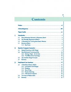
Figure 2 shows an example of an RTN subnet called PickNode. The execution of this subnet by the RTN interpreter starts at the initial state S 1 and then immediately passes to the input state ~2. A menu called NodeMenu is associated with this state. The user has now to select one of the two options in this menu. If, for instance, the option named Del is selected, the option transition T2 will be traversed, and the application call state ~3 will be reached. The semantic procedure DNode associated with this state will be called by the RTN interpreter. Finally, the return state S5 will be encountered, and the execution of the subnet will terminate. GUIDE provides an interactive graphic editor called SYNEDIT. This editor allows the user interface designer to construct the RTN which defines the syntax of the dialogue language. A SYNEDIT screen is shown in Figure 2. SYNEDIT checks the consistency and completeness of the RTN to make sure that it can be executed. The user interface for SYNEDIT itself was generated by GUIDE.
k-l+lfltl
SUSNET
PICKNODE
Text area
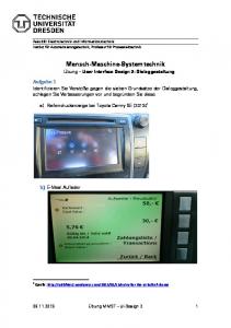
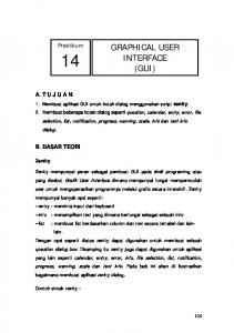
FIGURE3. Screen Layout for a Guide-Developed Application cases show the command language representation of the command being entered. This helps the user to learn the command language. Note again that each of the tokens in the command may be entered in a different dialogue mode. Furthermore, note that the user does not have to tell the system to switch between dialogue modes-but simply uses whichever device (mouse or keyboard) wanted. The different dialogue modes are managed solely by the lexical component. When the RTN interpreter receives a token from the lexical component, it has no knowledge of the mode in which this token was entered. This makes the system relatively easy to adapt to future dialogue modes and input devices (e.g., a speech recognizer) since only the lexical component will have to be changed, while the syntactic and semantic components will remain unchanged. GUIDE includes a program called LEXEDIT that allows the user interface designer to define icons, links, menus, and messages. In the icon editor screen (see Figure 4) the icon is drawn using graphic primitives and text fields. The icon is shown twice: life-sized in the corner of the screen and enlarged in the main window. In the link editor screen (see Figure 3, the designer can specify the attributes of the link: line style, arrowheads, and link shape. Text fields can be placed along the link. In the menu editor screen (see Figure 6), the menu’s graphic appearance is drawn. The name and the rectangular region occupied by each option in the menu can be defined. The designer has a choice of three menu styles: static, pop-up, and pull-down. This choice of facilities allows the implementation of many of the currently popular user interface styles.
IlILI+I-u~
EXAMPLES OF GUIDE-DEVELOPED APPLICATIONS In order to test the applicability of GUIDE in various areas, user interfaces for three different applications were constructed. The applications are:
53 DNode
4ddTrans 5254option
l
4ddState 4ddTrans MdTrans
l
I
Exit 53 S5 Plain S4 S5 Plain
I
FIGURE2. An RTN Subnet being Edited by SNYEDIT
November 1989
I1 l~l-+l+l
Graphic window area
The Lexical Component The lexical component of a GUIDE-generated user interface manages all the input and output of the program. The output consists of text messages, menus, icons, and links. A link is a line that connects two icons. Icons and links may be used to represent the different objects on which the application operates. They can, for instance, be employed to show the nodes and edges of the graphs that appear in some applications. GUIDE’s lexical component is called by the RTN interpreter (the syntactic component) when it encounters an input or output state. The lexical component currently supports two dialogue modes. Every menu, icon, or link can, therefore, be selected in one of two ways: by pointing with a mouse (an MM) or by typing the option’s or object’s name (a CLM). Text typed at the keyboard appears in a special CLM text area at the bottom of the screen (see Figure 3 and the examples in Figures 2 and 7). If the user employs the mouse, the name of the selected menu option or object will be copied by GUIDE into the CLM area as if the user has typed them in. The CLM area will, therefore, in all klclfltl
Scroll bar
Volume 32
Number 11
l
a directed graph editor, a specification program for management systems (MISS), and the RTN editor of the GUIDE system.
information
The directed graph editor is a small program. It was
Communications of the ACM
1355
Computing Practices
The use of AUIs can be illustrated with this directed graph editor. Suppose the end user wants to ad.d an edge from node v to node w. One way to do it i.s to type at the keyboard the command: AddEdge
FIGURE4. LEXEDIT’s Icon Editor Screen
FIGURE5. LEXEDIT’sLink Editor Screen &ENU EOfTOR: OPTIONS
uenu: uyuenu
f ,>Exit :,