by Nick Higham [17]. Generally, the estimate .... [5] S. M. Rae, D. R. Wilton, and A. W. Glisson, Electromagnetic scattering by surfaces of arbitrary shape, IEEE ...
,,
.,
“.
THE APPLICATION OF MASSIVELY PARALLEL COMPUTATION TO INTEGRAL EQUATION MODELS OF ELECTROMAGNETIC SCATTERING
Tom Cwik, Robert van de Geijn~ and Jean Patterson Jet Propulsion Laboratory California Institute of Technology Pasadena, CA 91109 bepa.rtrnent of Computer Sciences University of Texas Austin, TX 78660 .,
.,
Abstract Integral equation methods are widely used in the analysis and design of electromagnetic systems. Traditionally, the limiting parts of the simulation have been the memory needed to store the dense matrix, and the computational time needed to solve the matrix equation. In this paper we report on the extension of integral equation solutions to new wavelength regimes, and completion of the solution in an amount of time that is practical for engineering applications. The numerical solution of the integral equation is computed on scalable, distributed memory parallel computers. Essential to the numerical solution was the development of a complex valued, highly optimized, dense matrix equation solution algorithm for scalable machines. A portion of the work outlined in this paper is the development of this production level library routine for the solution of linear . equations on parallel computers, A convenient interface, useful for integral equation solutions among others, was specifically developed in this work. This algorithm has the conveniences offered by the sequentiaLlibranes, can be easily ported between parallel platforms, and has been placed in the public domaii.
This work was performed at the Jet Propulsion Laboratory, California Institute of Technology under a contract with the National Aeronautics and Space Administration. 1
‘ .
.,
., 1,
1. Introduction Integral equation methods are widely used in the analysis and design of electromagnetic systems. As witnessed by the wide range of problems solved over a period of nearly thirty years, these equations lend themselves to a convenient numerical solution [ 1]. Depending on the physical system considered, different integral equations can be written to model specific electromagnetic field or current components. For example, if the component being modeled consists of varying dielectric material such as the human body, a three-dimensionttl volume integral equation for the fields inside the body is written and solved. When the object is homogeneous or can be modeled as a perfect conductor, it is only necessary to write a three-dimensional surface integral equation for the fields, or equivalently induced currents, on the object’s surface. The integral equation usually models the surface to better than 10 parts per elecrnc,ai wavelength, and provides a stable solution for many types of components at many different elecrncal sizes. By using a moment method to solve:~he integral equation, a dense system of equations with corresponding matrix order proportional to the component’s electrical size is computed, and its solution yields the induced current and secondary observational quantities. Traditionally, the limiting parts of the simulation have been the memory needed to store the dense matrix, and the computational time needed to solve the matrix equation. Because a large number of useful engineering components are many wavelengths in size, simulations using integral equation methods are fundamentally limited by the amount of available memory. In this paper we report on the extension of integral equation solutions to new wavelength regimes, and completion of the solution in an amount of time that is practical for engineering applications. A numerical solution of the integral equation computed on scalable, distributed memory parallel computers will be outlined. Essential to the numerical solution was the development of a complex valued, highly optimized, dense matrix equation solution algorithm for scalable machines. This algorithm allows the efficient in-core solution of the linear system resulting from discretizing the integral equation. On conventional supercomputers, extensive libraries exist for solving the linear systems. Few, if any such libraries exist for parallel systems. Most routines that have been parallelized are research codes and have a cumbersome interface – if any. A portion of the work outlined in this paper is the development of a production level library routine for the solution of ~ linear equations on parallel computers. A convenient interface, useful for integral equation solutions among others, was specifically developed in this work. This algorithm has the conveniences offered b.y.the sequential libraries, can be easily ported between parallel platforms, and has been placed in th;public domain. 2. The Electromagnetic Integral Equation In this paper, the electric field integral equation (EFIE) for perfect conductors will be considered. This equation models a wide range of arbitrary objects including open and closed objects of arbitrary curvature and wires, and can be extended to handle surfaces with impedance coatings. The EFIE is derived directly from Maxwell’s equations using the Green’s function for 2
.
.
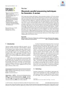
an unbounded homogeneous space, and the boundary condition for the tangential electric field on a perfect electric conductor. The scatterer surface is denoted S and has an outward normal i? (Figure 1). The total elecrnc field E is broken into incident and scattered parts, where the incident i field E is due to a time harmonic impressed source with time variation exp(jcot) radiating in the absence of the scatterer, and the scattered field E’ is due to induced currents and charges on the scatterer radiating in free space. Derived using magnetic vector and scalar potentials, the scattered field is written as [2,3] (1)
E’(r) = -jwpA(r) - V@(r) where the magnetic vector potential due to induced surface cwents J(r)
= fi x H(r) is
~- jkR ., .,
(2)
A(r) = ~~J(r’)=dr’
and the scalar potential due to a surface charge a(r) is (3)
~(r)=~j~~(r’)~~dr’ .
Here, His the tod magnetic field, R = Ir - r’1, and r and r’ Me arbitrw source and obswation points. The surface charge is also related to the surface current through the relation
where V: represents the surface divergence operator in source coordinates. Enforcement of the perfect conducting boundary condition ii x E = O on the surface of the scatterer results in the EFIE iix(jwpA+ V@)== fix Ei
rES
(5)
This is the equation that is discretized and solved using a method of moments solution. For the purposes of this paper, the associated magnetic field integral equation (MFIE) [2], combined field integral equation (CFIE~4], or other related integral equations used for specific problems could be utilized in the following ”numencal solution. 3. IXscretization of the Integral Equation A solution for the unknown induced currents on the scatterer is found from a numerical solution of the EFIE (5). PATCH, a well developed code that solves (5) is used in this work [5, 6]. Initially, the scatterers surface is tessellated into rnangular facets using standard geometry modelers and mesh generation packages. After replacing the surface charge in (3) by the surface 3
divergence as outlined in (4), the induced currents on the surface facets are taken as the sole unknown in (5). A moment method is used to reduce the EFTE to a set of linear equations [7]. The order of the resulting matrix equation is the number of induced current functions. In the PATCH code, the current existing on the scatterer is approximated by
J(r) = $~.fn (r)
(6)
Iw=l
where fn are the current expansion functions, 1. is the complex amplitude of the expansion function and N is the number of interior edges of the tessellated surface. A current expansion function consists of a pair of triangular facets attached at an edge [5]. This function has specific properties that make it useful for approximating an arbitrary current distribution on a general threedimedsional surface. It has the correct continuity of vector components across boundaries of mangle pairs; it properly models the surface charge in (3); and the use of rnangular facets allows an arbitrary scatterer surface to be modeled. Following the method of moments, a set of linear equations for the unknown amplitudes I. is produced by testing (5) with an independent set of functions. The testing set is chosen to be identical to the current expansion functions, f, [5]. A symmernc inner product (7) is defined, yielding the matrix equation (8) By testing with the same N functions used in (6), a NxN set of equations results ZI=V
(9)
where Z is the imped~:~ matrix, I is the vector of unknown current amplitudes, and V is the .-arexcitation vector. The numerical solution of (9) generally proceeds by computing the impedance matrix elements, factoring it into a LU decomposition, and solving for the induced current given an excitation. Observable quantities such as the radar cross section, are then computed from the known current amplitudes. When using a shared memory machine, the impedance matrix is stored in memory and operated upon. When a distributed memory machine is used, the marnx must be broken into pieces and disrnbuted across the memory of all processors in use. The manner in which the marnx is decomposed is dependent upon the matrix solution algorithm. General 4
.,
information on the description and application of distributed memory, parallel computer architecture for electromagnetic computation can be found in [8, 9]. 4. The Parallel Dense Matrix Equation Solver In this section, we describe a state-of-the-art parallel dense matrix solver routine developed during the course of this work. This routine is very similar to those included in a prototype ScaLAPACK library [10]. The main advantages of this routine area friendly user interface and an efficient and highly accurate condition number estimator. In the design of this parallel dense matrix equation solver, the following issues were taken into accounb .>
H&archical memory on each node; the amount of memory and its organization on a processor must be take into account to achieve high performance [11,12]. Data decomposition resulting from the integral equation formulation; the algorithm which calculates the marnx entries may lead to a natural decomposition of the matrix among the processors. Data decomposition that leads to an efficient marnx factorization; the factorization algorithm may require a specific decomposition of the matrix among the processors for high performance. This decomposition will be based on communication and scalability issues. In general this decomposition and the decomposition due to the integral equation will not coincide. Indeed, a usable and efficient interface between the parallel marnx equation solver, and the matrix computation segments of the code are essential. Robust solution of the matrix equation; the solver must produce stable results and yield an estimate of the stability of the system. The fwst issue requires us to start with an approach that has merit on a conventional supercomputer. The second and third indicates the possible conflict between the data decomposition requirecLby the application versus the data decomposition that leads to optimal performance of the dens~rnarnx equation solver. The robustness of the solver indicates that the problem may yield a matrix that requires pivoting to produce an accurate result. Moreover, the application may need to know information about the conditioning of the linear system. We will address each of these issues in subsequent sections. 4.1 Optimal use of Caches Considered solving the dense linear system (9), written as 5
I
(lo)
Ax=b
where A E C“Xa. Ignoring for the moment the use of pivoting for stability, it is customary to perform this operation by first computing its LU factorization (11)
A=LU
where L is lower triangulm with unit diagonal, and U is upper triangular. The system can then be solved by computing Ly=b
(12)
Ux=y
(13)
followed by
In the past, this could be easily accomplished by calling the appropriate LINPACK [13] library routines. On a typical processor with hierarchical memory, the LINPACK routine will not perform anywhere near the processor’s peak rate. One reason is that the implementation is rich in vectorvector operations, which makes access to main memory a bottleneck. In essence, O(n) operations are performed on O(n) data, and the processor cache, which allows high data access rates, cannot be utilized optimally [12]. LAPACIS [14] corrects this by reformulating the factorization in terms of matrix-marnx operations. Partition A, L and U as follows (14) where All, Al, Ull ~::. This leads to the equations .-v-
(N=(2)U1] 42= fw12
42- M-J12
=
J5J-J22
6
(15) (16) (17)
#
We see that the LU factorization can be fommlated by overwriting a panel of width k with its LU factorization (15), foilowed by solving the triangular system with multiple right-hand-sides (16). Finally, the bulk of computation is in updating &, using a marnx-matrix multiplication, followed by a recursive factorization of the result (17). During the update of ~, 2k(n - k)2 operations are performed on (n+ k)(n - k) data, allowing data to be brought into cache, after which a large amount of computation occurs before it is returned to memory. This overcomes the memory access bottleneck. 4.2 Parallel Implementation Now that we have identified an appropriate approach for a sequential algorithm, it must be parallelized. However, we must keep in mind that the resulting algorithm will be called after the matrix has been calculated. Hence, we will first discuss how a user may wish to view the assignment of portions of the matrix to processors. Assume that the physical processors, Pij form a logical two dimensional p, x pc array, where i and j refer to the row and column index of the processor. Then the simplest assignment of matrix elements to processors is to partition the matrix
(18)
where BU e Cm’x”~, mi = n/p,, and n j =nfpc. Submarnx Bti is then assigned to processor Pti. A straight forward parallel LU factorization, again ignoring pivoting, can now proceed as follows: Assume in (14) the column panel consisting of Al and 41 resides within a single column of processors, while the row panel consisting of Al ~ and A12 resides within a single row of processors. The process starts by having processors that hold portions of the column panel collaborate to factor that panel. Next, the result can be broadcast within rows of processors to the other columns. The row of processors that holds 41 can then in parallel update this panel. Finally, & must be ovgwritten by & - ~lUlz. Concentrating on an arbitrary processor Pij> observe that only portions%f Al that reside in row i must be present on this processor, as well as portions of U12 that reside in column j. The former submatrix is already on the processor due to the broadcast of the factored panel within rows. The latter can be brought to the appropriate processors by broadcasting portions of U12 within columns of processors. While the above scheme is straight forward, it can be easily seen that it does not yield a well disrnbuted workload. Indeed, as the algorithm recursively proceeds with updated submatrix &, eventually processors become idle, until eventually only one processor is busy. This can be
7
.
.
overcome by blocking the matrix into much smaller k x k submarnces, and wrapping these in two dimensions onto the logical processor array. In other words, partition
A=[*]
(19)
where ikf=rnlk,and N=nlk and all blocks are of size k x k. Then block CV is assigned to processor ‘fi~~~,)(~~d PC )” ‘e algorithm proceeds as before, but as the problem deflates, processors continue to participate. Adding pivoting to this approach is relatively straight-forward [15,10,16]. .,
.>
4.3 Interface
Clearly, it is not reasonable to require the matrix fill portion of the application to generate the matrix in wrapped form. We now show that the matrix can be generated in the more convenient form given in (18), while the computation can assume it is wrapped as in (19), without any need to pe~orm communication. Consider what would happen if the matrix is generated as in (18) by the application, after which the library routine is called that assumes the marnx was wrapped as in (19). It is not hard to see that in effect, the LU factorization computed as a result is that of apemmted matrix (20)
However, we are not interested in the factorization. We are interested in solving the system Ax= b. It is natural to assume that vector b is disrnbuted like a column of A, while the solution vector is disrnbitted like a row of A. After all, elements b correspond to rows of A, while elements of x correspond to columns of A. If these vectors are distributed con formal to the original matrix A, the solver will view the right hand side as a permuted vector & = P,zPb. It will proceed to solve the system .* .-lr(21) &=6 leaving the result vector Z wrapped onto a row of processors, passing this solution back to the application. Finally, the application views the resulting vector as the actual solution x, distributed among a row, but not wrapped. This is equivalent to viewing Pj~A,Z as the solution vector x. However, 8
(22)
zi=h is equivalent to (P~fiApri@)i
=
‘&Jb
(23)
and
)
A(Ptith,.i = b
(24)
Notice that while the solver views both matrix and vectors as being wrapped and the matrix fill algorithm views them as blocked, the resulting interpretation of the answer yields a correct soluti~n vector. 4.4 Condition Number Estimation The condition number estimator provided by LINPACK is generally regarded as a good method for obtaining a useful lower bound for estimating the one-norm of a given marnx. Once the matrix is factored, the cost of this estimate is the computation of a few triangular solves, and therefore of little consequence for large marnces. More recently, a better estimator was proposed by Nick Higham [17]. Generally, the estimate returned is accurate practically to machine precision. While more expensive than the LINPACK estimator, the cost remains on the order of that of a number of triangular solves. It is this estimator that has been incorporated into LAPACK. Conveniently, it is the LAPACK-style condition number estimator that parallelizes better. Ignoring the possibility of overflow for very ill-conditioned mamces which a full implementation of the LAPACK estimator would guard against, this estimator becomes a sequence of parallel rnanguiar solves. It is this algorithm that has been incorporated into our solver. Details go beyond the scope of this paper. 4.S Scalability and Performance .+ The data decorn+position used by the solver is specifically designed to yield high performance. Moreover, it is designed so that this performance scales well with the number of processors of the parallel computer. While details of the analysis of the implementation is clearly beyond the scope of this paper, we will sketch the implications of the design issues below. The interested reader can find details in [10]. As noted previously, the scattering problem we are solving is of sufficient complexity that the problem size is limited by the capabilities of the computer being used, at least currently. In our case, the limitaaon is the size of the aggregate memory of the parallel computer. As a result, we 9
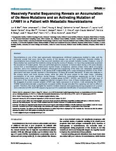
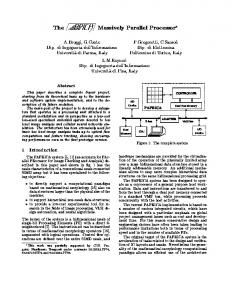
would hope that a large pa.dlel system being used for the largest problem that fits in its memory, would be as efficient as a similar, but smaller parallel system when solving the largest problem it is capable of handling. The analysis in [10] shows that for the approach taken here, efficiency can be maintained as long as the matrix dimension increases with the square-root of the number of processing nodes. Since storage requirements grow as the marnx dimension squared and as the square-root of the number of processors, these requirements are met. This property is illustrated by the experimental data obtained on the Intel Touchstone Delta. In Figure 2, we see that as the number of nodes is increased, the problem size increases, but the efficiency, or performance per processor, remains constant. Figure 3 shows the overall performance attained by our linear equation solver as a function of problem size for different numbers of processors. Figure 4 shows the similar result for CPU time to solve the linear system. The largest matrix system (n= 16,200) took less than 19 minutes to solve,~n 512 processors of the Touchstone Delta. It should be noted that the peak performance of each individual processor is in the 35-40 MFLOPS range for this kind of problem, indicating we are achieving better than 50% of peak for this part of the computation. Moreover, all performance graphs include the condition number estimation, and forward and backward substitution phases of the linear solve, which do not generally perform well on parallel computers. 5. Parallel Computation of Matrix Elements As outlined in Section 4.3, the marnx equation solution algorithm operates on marnx data that has been mapped to the processors memory in a specific manner. This algorithm requires that contiguous blocks of the matrix be stored in each processors memory. When viewed as a library routine, it is of no consequence that the algorithm operates on a permuted version of the impedance marnx, since the resultant current vector is returned correctly ordered. It is essential though, that the algorithm operates on the wrapped version of the matrix when performing the matrix factorization and solution, since without this wrapping the soIvers performance would greatly suffer. Each processor calculates its piece of the impedance matrix as shown in (18). The parallel machine is viewed as a two-dimensional grid of processors – typically, a ratio of 1 row to 8 columns is found to giv.aptimum performance. On a 512 processor machine, the grid is therefore 8 by 64 resulting in blck~s of the marnx being approximately n/8 rows by n/64 columns in size. Since the matrix order will not in general be a multiple of the number of processor rows and columns, blocks in the bottom row and right-most column will be slightly smaller in size. When computing marnx elements, each processor only needs to calculate those rows and columns corresponding to its block, skipping the other marnx element calculations. In the PATCH code, the current basis functions associated with a triangular patch correspond to the columns of the impedance matrix and those of the testing patches correspond to the rows.
10
Ideally, parallel computation of the matrix elements would proceed by looping over row and column indices, performing the integrations necessary to compute marnx elements in the block of elements that reside in each processor. In the original PATCH code, to speed the sequential execution of the fdl algorithm, it was initially recognized that calculations performed at the center of a patch are common to its three edges. It was efficient to compute the integrals associated with a triangular patch and distribute the results over elements of the matrix associated with the three edges of the patch. The marnx fill algorithm of PATCH therefore loops over pairs of current and match triangular patches. In the parallel computation of the matrix elements, an amount of redundancy develops at this stage since the three edges of both the source and testing patch corresponding to row and column indices of a matrix entry - will not generally reside in one processor. The calculations not contributing to the edges associated with the processor performing calculations are therefore thrown out since they are being duplicated in the processors where they are used. This redundancy can be removed by performing the calculations once, communicating the matrix entry to its correct processor and storing it in its proper location within the matrix block. By pe~ortning this communication, no calculations would be repeated, though extra time would be needed for communicating the data. Because of this unknown overhead, and because of the added complexity in coding, this step was not taken. It is noted that if a different integral equation formulation results in matrix elements that have no calculations in common, this redundancy is naturally removed. 6. Parallel Computation of Observable With the major part of computations and parallelization completed, all that remains is to calculate observational quantities associated with the scatterer. In PATCH, these are mainly the near and far-fields, and associated radar cross section. Field calculations are completed by performing the forward integration of the now-known currents, and Green’s function evaluated at given near or far-field observation points. Because of the discretization of the current in (6), this integration results in a sum of the individual field components due to each current basis function. The parallelization of this integration is completed by bre~king the sum into ,parts equally disrnbuted over all processors. Since the solution vector has been distributed to all processors, the decomposition is rudimentary – each processor calculates field components due to current basis functions associated with a set of rnangular patches. The partial sums are then added together to produce the field or cros~section at a specific observation point. . *7. Performance and Results With the matrix equation solver fully integrated into the PATCH code, results can be obtained for various size problems run on different machine sizes. The following results were made on the Intel Touchstone Delta. A perfectly conducting cube scatterer is modeled with varying mesh densities. Two types of results were tabulated. First, results for scaled problem sizes are shown in Figure 5. In this case, the size of problem modeled - as represented by the marnx order 11
.
is increased proportionally with the number of processors used. Components of the code are broken out of the total time and displayed in Figure 5. It is seen that the computation time is dominated by the matrix fill and factor portions of the computation. The solution was found for a single excitation, and the radar cross section was calculated in three planes in one degree increments. For the largest size problem that fits in 512 processors, total execution time required was 39.4 minutes. The second set of results are for fixed size problems. Three different problem sizes are considered -3042, 8712, and 12,168 unknowns. For each size, the probiem is run on the smallest sized machine it fits on, as well as larger machines. As seen from Figure 6, total execution time decreases as the fixed size problem is run on larger machines. A point of diminishing returns is reached where the use of a larger machine will not significantly decrease solution time. This point has been reached for the case of 3042 unknowns, but not yet for the largerh,fizes. In Figure 7 the computed radar cross section is compared against measurements for a cube of side 5 wavelengths [18]. The total surface area modeled is 150 square wavelengths since no symmetry was utilized; 16,200 unknowns were used to model the induced current. Results in three planes are shown for broadside incidence. 8. Summary This paper has outlined a numerical solution to integral equations completed on massively parallel computers. Essential to this numerical solution was the development of a parallel, high performance, dense matrix equation solution algorithm. Key to this development was an efficient and simple interface to the matrix fill portion of the inte=gral equation code. This parallel routine can be obtained via anonymous ftp at cs.utexas.edu, in directory pub/rvdg/complex. solver, as well as from the electromagnetic software library EMLIB at microwave.jpl.nasa. gov, in directory pub/pAlel/complex. solver. Because of the large disk storage available on parallel computer systems, a natural extension of the above work is an out-of-core algorithm for use with integrai equation codes. Initial work in this area was described in [19] where a 48,672 order matrix equation resulting from the EFIE was solved. @.isting systems will allow for the storage of marnces of nearly twice this dimension. Current eff&t is underway to produce efficient and highly performing out-of-core algorithms sirnhr to those reported in this paper. Acknowledgments This project was supported in part by Intel SSD, in part by DARPA under contract number DAAL03-91-C-0047 administered by ARO, and in part by DOE under contract number DE-AC05840 R21400. This research was performed in part using the Intel Touchstone Delta System 12
.
’
.
operated by Caltech on behalf of the Concurrent S upercomputing Consortium. Access to this facility was provided by NASA. References [1] E. K. Miller, A selective sumey of computational electromagnetic, IEEE Trans. APS, vol. M-36, pp. 1281-1305, Sept. 1988. [2] A. J. Poggio and E. K. Miller, Integral equation solutions of three-dimensional scattering problems, in Computer Techniques for Electromagnetic, R. Mittra Editor, Hemisphere Publishing Corp., New York, 1987. [3] R.LF. Barrington, Time Harmonic Electromagnetic Fields, McGraw-Hill, New York, 1961. ., [4] J. R. Mautz and R. F. Barrington, A combined-source solution for radiation and scattering from a perfectly conducting body, IEEE Trans. APS, vol. AP-27, pp. 445-454, July, 1979. [5] S. M. Rae, D. R. Wilton, and A. W. Glisson, Electromagnetic scattering by surfaces of arbitrary shape, IEEE Trans, AP-30, pp. 409-418, May, 1982. [6] W. Johnson, D. R. Wilton, and R. M. Sharpe, Modeling scattering from and radiation by arbitrary shaped objects with the electric field integral equation rnangular surface patch code, Electromagnetic, vol. 10, pp. 41-64, Oct., 1990. [7] R. F, Barrington, Field Computation by Moment Methods, IEEE Press, New York, 1993. [8] T. Cwik and J. Patterson, Editors, Computational electromagnetic and supercomputer architecture, Progress in Eelctromagnetics Research, vol. 7, EMW Press, Boston, In Press. [9] T. Cwik, Parallel decomposition methods for the solution of electromagnetic scattering problems, Electromagnetic, vol. 12, pp. 343-357, Dec. 1992. [10] J. J. Dongarra, R.. wan de Geijn, and David Walker, A look at scalable dense linear algebra libraries, Proceedings o~Scalable High Pe~ormance Concurrent Computing ’92, April 27-29, 1992. [11] J. J. Dongarra, J. Du Croz, S. Hammarling and I. Duff, A Set of Level 3 Basic Linear Algebra Subprograms, Trans. Math. Soff., vol. 16, No. 1, pp. 1-17, 1990. [12] J. J. Dongama, I. S. Duff, D. C. Sorenson, and H. A. van der Vorst, Solving linear systems
on vector and shared memory computers, SIAM, Philadelphia, 1991.
13
[13] J. J. Dongarra, J. Bunch, C. Moler, and G. W. Stewart, LINPACK User’s Guide, SIAM, Philadelphia, 1979. [14] E. Anderson, Z. Bai, J. Demmel, J. Dongarra, J. DuCroz, A. Greenbaum, S. Hammarling, A. McKenney, S. Ostrouchov and D. Sorensen, LAPACK Users’ Guide, SIAM, Philadelphia, 1992. [15] R. van de Geijn, Massively parallel LINPACK benchmark on the Intel Touchstone DELTA and iPSC/860 systems, Dept. Comp. Sci., U of Texas, TR-91 -28:, 1991. [16] R. van de Geijn, Dense Linear Solve on the Intel Touchstone Delta System, CornpCon92, 37th IEEE Computer Society International Conference, Feb. 24--28, 1992. [17] ~.J. Higham, FORTRAN Codes for Estimating the One-Norm of a Real or Complex Marnx, with Applications to Condition Estimation, ACM Trans. on Math. Software, Vol. 14, No, 4, pp. 381-396, 1988. [18] M. G. Cote, M. B. Woodworth, and A. D. Yaghjian, Scattering from the Perfectly Conducting Cube, IEEE Trans AP-36, pp. 1321-1329, Sept. 1988. [19] T. Cwik, J. Patterson, and D. Scott, “Electromagnetic Scattering Calculations on the Intel Touchstone Delta,” Proc. IEEE Supercompuzing 92, Minneapolis MN, pp 538-542, Nov 16-20 1993. (Gordon Bell Prize Finalist paper also summarized in IEEE Computer, Jan 1993.)
14
z ii
t
/’!++
E
i
Hi ki Y
I
I I / r
/
J---Y / s
s
/ x
Figure 1. Geometry of cube scatterer of sides. Surface of scatterer is denoted S.
..-8r-
15
PERFORMANCE PER PROCESSOR A7TAINED BY SOLVER 25
~3,042 .
20 Y
J
I 5,832
I 12,168
8.5
9.25
16,200
8.2
1
15
3
10
.. .,
5
0
r O
, 64
, 128
, 192
, 256
, 320
,
384
#
448
5“i2
NUMBER OF PROCESSORS
Figure 2. Performance per processor as a function of the number of processors. At each data point, the marnx size is given, as well as the number of million bytes used on eaeh processor to store the matrix.
.+0. *-
.’.
TOTAL PERFORMANCE ATTAINED BY SOLVER ,
12 1 J
~lo .CJ
58
●
6
##
..
●
.
*#
4 *-
●
largest problem that
2
fits on given number of
E- - - . --*- .
0
,
2
r
,
4
-
processors
,
r
6
,
,
1
3
,
t 1
,
,
i ,
, I
I
r
8 10 12 MATRIX DIMENSION (x1OOO)
,
, I
14
I
I
1
,
t
16
,
,
1’
Figure 3. Total performance of solver on different size machines (p is the number of processors in use). Dotted line is performance for scaled problem, i.e., largest size problem that fits on given machine size.
17
.
TOTAL TIME TO SOLVE SYSTEM
Zu
14 ~12 E
~lo 2
.>
4“ .,
-- --
20: 1 1
2
1
I
4
1
I
1
1
6
r
1
I
,
1
8
,
1
10
MATRIX DIMENSION
,
,
s
12 (X
I
1
14
8
I
r
16
1
,
18
1000)
Figure 4. Total time to solve system on different sized machines (p is the number of processors in use). Dotted line is time for scaled problem, i.e., largest size problem that fits on given machine size.
18
I
.
d AA I
vu a
10
TOTAL TIME FOR INTEGRAL EQUATION SOLUTION SCALED SIZE PROBLEM I
1
I
I
I
I
1
I
TOTiL FILL FACTOR
u l– “ I
I
j
RCS ., .,
I
d
0.01
, I 1
1 1 , 2
0
I 1
1
1
I
I
1
4
,
6
I
,
I
8
MATRIX DIMENSION
I
1
lb (X
1
1>
r
1
1
1“4
1
r
16
1
1
1’8
1000)
Figure 5. Total time for integral equation solution for scaled problem, i.e., largest size problem that fits on given machine size.
.40.
*-
19
I
.
TOTAL TIME FOR INTEGRAL EQUATION SOLUTION FIXED SIZE PROBLEM
30 25-
,
20
LLl
z i=
15 “ 10:
., .,
5 o“ o
8
,
64
1
128
,
1
192
256
1
1 320
1
384
I
448
NUMBER OF PROCESSORS
Figure 6. Total time for integraJ equation solution for fixed size problem.
20
5
.
THETA (deg)
45 ~ 40 ~ 35 ●N 30 “m 25 z g ;: .s10 “5 o THETA (deg)
50
RADAR CROSS SECTION 45”-PLANE I I I I I I i
THETA (deg)
I
f
Figure 7. Radar cross section in three planes for broadside incidence on cube of side 5 wavelengths. 16,200 unknowns were used to model the induced current on this object. 21


![FREE [DOWNLOAD] PROGRAMMING MASSIVELY PARALLEL ...](https://m.moam.info/img/260x300/free-download-programming-massively-parallel-_64789e54097c4744708d088f.jpg)