GRAND CHALLENGES IN EARTH SYSTEM MODELING
THE ARCHITECTURE OF THE EARTH SYSTEM MODELING FRAMEWORK The Earth System Modeling Framework (ESMF) project is developing a standard software platform for Earth system models. The standard, which defines a component architecture and a support infrastructure, is being developed under open-software practices. Target applications range from operational numerical weather prediction to climate-system change and predictability studies.
H
istorically, researchers have developed large-scale Earth science applications, such as ocean and atmosphere models, under monolithic software-development practices, usually within a single institution. Over the past decade, an emphasis on integrated multicomponent modeling has emerged—reflecting an increase in scientific capabilities and computing capacity, and resulting in several ambitious, coupled, Earth system modeling efforts. In these coupled efforts, which span institutions and disciplines, the current monolithic software-development practices can seriously hamper continued innovation in complex, highly integrated simulations. Most notably, current practices hinder broad com-
1521-9615/04/$20.00 © 2004 IEEE Copublished by the IEEE CS and the AIP
CHRIS HILL Massachusetts Institute of Technology
CECELIA DELUCA NSF National Center for Atmospheric Research
BALAJI NOAA Geophysical Fluid Dynamics Laboratory
MAX SUAREZ AND ARLINDO DA SILVA NASA Global Modeling and Assimilation Office
18
munity sharing of software renditions of Earth system modeling algorithms. This affects both modeling and innovation as well as the ability to effectively synthesize models with data assimilation. In the latter case, the increased volume and availability of rich observational data streams, especially from spaceborne remote-sensing platforms, requires specialized data-assimilation software to rigorously combine models and data. The absence of technology and standards to let researchers share software results in redundant development and impairs technology transfer, which in turn impacts scientific progress. On the Earth System Modeling Framework (ESMF) project, we are building standards-based open-source software that aims to increase software reuse, component interoperability, performance portability, and ease of use in Earth science applications. The project is a multi-institutional, crossdisciplinary collaboration that includes many of the largest Earth science modeling centers in the US; the NASA Computational Technologies Program is funding the initial three-year effort. In this article, we describe the ESMF’s architecture, focusing on the features that enable it to be flexible enough to accommodate a wide and continually evolving suite of modeling tools.
ESMF Project Scope ESMF’s specific focus is Earth system modeling. Targeting this diverse but bounded domain permits
COMPUTING IN SCIENCE & ENGINEERING
a design and implementation strategy that satisfies user requirements to an extent not possible with generic software. ESMF has 15 initial testbeds that represent several major modeling efforts (see www.esmf.ucar.edu for the test code). These efforts, such as the Geophysical Fluid Dynamics Laboratory’s (GFDL’s) Flexible Modeling System (FMS; www.gfdl.gov/ fms) and the National Center for Atmospheric Research’s (NCAR’s) Community Climate System Model (CCSM),1 represent research and operational applications in climate, weather, and data assimilation. The testbed systems thus span a variety of discrete grid approaches, numerical time-stepping techniques, software-programming paradigms, and hardware platforms. The overall domain, however, is sufficiently focused to allow identification of common domain-specific data and control constructs and abstractions.
The ESMF Team The Earth System Modeling Framework project encompasses many researchers from many institutions. The large Earth science modeling centers in the US involved in the project include the Geophysical Fluid Dynamics Laboratory (GFDL), National Centers for Environmental Prediction (NCEP), National Center for Atmospheric Research (NCAR), Los Alamos National Laboratory (LANL), Argonne National Laboratory (ANL), Goddard Space Flight Center (GSFC), Jet Propulsion Laboratory (JPL), the Massachusetts Institute of Technology (MIT), and the University of Michigan. The members of the ESMF joint specification team are Balaji, Cecelia DeLuca, Chris Hill, Jeff Anderson, Byron Boville, Carlos Cruz, Nancy Collins, Tony Craig, Arlindo da Silva, Bob Hallberg, Mark Iredell, Rob Jacob, Phil Jones, Brian Kauffman, Erik Kluzek, Jay Larson, John Michalakes, David Neckels, Will Sawyer, Earl Schwab, Max Suarez, Shepard Smithline, Atanas Trayanov, Silverio Vasquez, Jon Wolfe, Weiyu Yang, Mike Young, and Leonid Zaslavsky.
Motivation and Impacts The ESMF project will affect Earth system modeling in a wide range of situations. We plan to show these impacts with a series of interoperability demonstrations that use previously incompatible state-of-the-art simulation codes (see Figure 1). Currently, these configurations are impractical, but our interoperability demonstrations will show how ESMF can remove technical barriers. Table 1 lists the model configurations we plan to demonstrate; we’ll now describe the potential science impacts of some of these demonstrations. Numerical Weather Prediction
Large-scale atmospheric simulation has been a key ingredient of numerical weather prediction since the 1950s. Because forecast skill is especially sensitive to boundary conditions, we’ll demonstrate operational forecast model configurations in the project that couple an atmospheric simulation to an interactive ocean at the lower boundary. In Figure 1, this corresponds to connecting the National Centers for Environmental Prediction’s (NCEP) Weather Research and Forecast (WRF, Figure 1f) models with the GFDL’s FMS suite (Figure 1b). Such a capability has direct relevance for forecasting tropical storm paths more accurately, which is significant to coastal communities and maritime enterprises. Seasonal and Interannual Forecasts
Forecasts of seasonal or interannual (SI) phenomena are an increasing area of interest. Evidence suggests that accurately forecasting ocean conditions (for example, the El Niño and La Niña phenomena in the Pacific Ocean) could improve the predictability of
JANUARY/FEBRUARY 2004
Table 1. New application configurations from the ESMF project. Model 1 GFDL atmosphere
Model 2 MIT ocean
GFDL ocean
NCEP atmosphere LANL sea ice
NSIPP ocean
NSIPP atmosphere DAO analysis
DAO analysis NCEP model
DAO atmosphere
NCEP analysis
NCAR atmosphere
MIT ocean
NCEP/ WRF atmosphere
GFDL or other ocean
New science enabled Introduction of global biogeochemistry into seasonal forecasts New seasonal forecasting system Extension of seasonal prediction system to centennial timescales Assimilated initial state for seasonal prediction system Intercomparison of systems for NASA/NOAA joint center for satellite data assimilation Intercomparison of systems for NASA/NOAA joint center for satellite data assimilation Component exchange for improved climate prediction capability Development of hurricane prediction capability
DAO: NASA’s Data Assimilation Office; GFDL: Geophysical Fluid Dynamics Laboratory; LANL: Los Alamos Nat’l Laboratory; NCAR: Nat’l Center for Atmospheric Research; NCEP: Nat’l Centers for Environmental Prediction; NSIPP: NASA Seasonal and Interannual Prediction Program; WRF: Weather Research and Forecast model
land-surface conditions (such as soil moisture content). Coupling sea ice into SI prediction systems under ESMF is one way that will let researchers explore and apply such ideas. In Figure 1, this corresponds to con-
19
(a)
(b)
(c)
(e)
(d)
(f)
Figure 1. Illustrations from models to be used in Earth System Modeling Framework (ESMF) interoperability demonstrations. (a) The Data Assimilation Office’s PSAS system, (b) the Geophysical Fluid Dynamics Laboratory’s FMS system, (c) MITgcm, (d) the National Center for Atmospheric Research’s CCSM, (e) NASA’s Seasonal and Interannual Prediction Program, and (f) NCAR and the National Centers for Environmental Prediction Program’s WRF. Currently, these modeling systems are computationally incompatible, but under ESMF, they’ll be compatible while also continuing to evolve and develop independently.
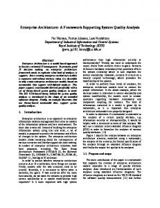
Earth System Modeling Framework superstructure User code Earth System Modeling Framework infrastructure
necting the NASA Global Modeling and Assimilation Office (GMAO, Figure 1e) seasonal forecast models with elements of NCAR’s CCSM (Figure 1d). Climate Change
To improve decadal and centennial climate-change estimates, we Figure 2. The Earth System can use ESMF to configure interModeling Framework “sandwich” operability demonstrations that architecture has an upper-level involve new interchanges of cli(superstructure) layer and a mate-model components. These lower-level (infrastructure) layer. configurations will lay the foundaArrows illustrate that the tion for studies that can examine superstructure-layer code (as well the impact of large-component inas user code) can call the terchange on climate-simulation infrastructure layer. trajectories. In Figure 1, this corresponds to connecting ocean– biogeochemistry configurations in the Massachusetts Institute of Technology (MIT) General Circulation Model (MITgcm, Figure 1c) with elements of the CCSM and FMS suites (Figure 1b and d)
Software Frameworks Addressing the interoperability and productivity issues mentioned earlier does not require us to develop new science codes. Instead, ESMF’s software framework provides a custom environment that
20
supports a broad range of simulations. Software frameworks build on the rich, flexible linguistic concepts of object-oriented languages, especially typing via classes, encapsulation, polymorphism, and inheritance. The NWChem2 and Cactus3 frameworks are examples of established multi-institutional, high-performance computing framework efforts in computational chemistry and general relativity, respectively. Both systems provide high-level abstractions and programming environments framed in terms of the science workflow of the domains they service. In the Earth science community, initial domain-specific, framework-related efforts include the FMS, the Goddard Earth Modeling System (GEMS),4 the WRF,5 the MIT wrapper toolkit,6 the CCSM, the Pilgrim communications toolkit,7 and the modelcoupling toolkit (MCT).8 The ESMF software framework architecture described in this article aims to unify, standardize, and extend all these efforts. The ESMF architecture also leverages lessons and technology from more general high-performance computing frameworks such as POOMA,9 Overture,10 and STAPL (Space-Time Adaptive Processing Library).11 These efforts provide many useful abstractions for key mathematical constructs on high-performance parallel systems. An important paradigm that many software frameworks use is component-based development. Accordingly, we’re also incorporating ideas and technology into ESMF from mainstream component-based programming environments such as Corba and the Common Component Architecture (CCA)12 high-performance-oriented componentprogramming environment. Naturally, the component model the ESMF architecture supports will be tailored to the requirements of high-performance Earth science models.
Architectural Overview A sandwich pattern characterizes the ESMF architecture (see Figure 2). User-code components that implement an algorithm’s scientific elements—for example, evaluating finite-difference calculations or radiationphysics terms—fit between two layers: superstructure and infrastructure. The superstructure layer’s role is to provide a shell that encompasses user code and a context for interconnecting input and output data streams between components. The infrastructure layer provides a standard support library that developers can use to speed up construction of components and ensure consistent, guaranteed component behavior. Programming Paradigm
A complete executable assembly of superstructure,
COMPUTING IN SCIENCE & ENGINEERING
user-code, and infrastructure components collectively forms an ESMF application. Figure 3 shows a single-tier composition with three hypothetical components and captures the essence of the compositionbased programming paradigm that ESMF uses. Connecting one or more numerical simulations or other user-code components in an ESMF-based environment forms an application (Figure 3a). Users write or modify code components (Figure 3c) to fit into the ESMF environment that envelopes the code and supports a unified high-level viewpoint for connecting data and controlling flow between components. The foundation-level infrastructure (Figure 3b) accelerates development and ensures compatibility and consistency among components and between hardware platforms. ESMF encourages multitier composition (in which components are recursively nested). Usercode components that don’t maintain internal persistent state on return can be safely instantiated multiple times in the same application under ESMF. Existing Codes
The Earth science community has a large body of existing Fortran codes that predate the development of object-oriented languages and contain features not ideally suited to a component framework. Persistent internal state in global data structures presents subtle problems. Specifically, problems arise if we create two copies of the same legacy-codederived component in a single process, or if components derived from different legacy codes happen to use the same global names. The ESMF architecture lets us convert such codes into components, but their safe use under ESMF will be limited to configurations in which each instance of a component executes in its own set of processes. Existing codes also include both single-program, multiple-data (SPMD) applications and multipleprogram, multiple-data (MPMD) applications. ESMF supports both these programming models, so components derived from existing SPMD or MPMD code bases fit easily into its architecture. These features will make it possible to effectively and productively use ESMF with many existing codes. ESMF’s initial release in May 2003 provided examples of how to use it in an SPMD mode with newly created components. As the interoperability experiments become hardened, we’ll make examples available that show migration of existing codes to ESMF in both SPMD and MPMD form.
Superstructure Layer ESMF superstructure layers furnish a unifying context within which to interconnect user components.
JANUARY/FEBRUARY 2004
1. ESMF provides an environment for assembling components Application driver Gridded components
Coupler components
(a) 2. ESMF provides a toolkit that components use to • ensure interoperability • abstract common services
(b)
Component run(), checkpoint(): Field: halo(), import(), export() + I/O
Grid: regrid(), transpose() + Metrics
DELayout, PEList, Machine model
3. Gridded components and coupler components are user written (c)
Figure 3. The Earth System Modeling Framework (ESMF) programming paradigm. An application is an assembly of (a) one or more gridded and coupler components. Components can use the (b) ESMF infrastructure toolkit, but all components are primarily (c) user written.
Superstructure-layer classes provide the foundation for a flexible mechanism to address physical consistency between components that might use different dimensions or units to represent the same quantity, or that may partition physical data differently on a parallel computer. Classes called gridded components, coupler components, and ESMF states are used in the superstructure layer to achieve this flexibility. ESMF State Class
User-code components under ESMF use special objects for component-to-component data exchanges. These objects are of type ESMF state; every component accepts one or more ESMF states as import states and produces one or more ESMF states as an export states. The ESMF state type supports methods that allow user-code components, for example, to fill an ESMF state object with data to be shared with other components or to query a state object to determine its contents. The ESMF state class includes fields used to describe the data that a state object holds. The conventions used to describe fields are not, however, prescribed by ESMF. We designed the ESMF state abstraction to be flexible enough to not need to mandate a single standard for describing fields. For example, ESMF does not prescribe the units of quantities exported or imported; instead, it provides mechanics to describe the units, memory layout, and grid coordinates of the fields contained within import and export states. This lets the ESMF software support user-community-defined standards for describing physical fields. The interoperability experiments
21
Phase 1. Creation creates components and registers user-code procedures for methods called in later phases. Create steps also are called for gridded component COMPONENT2 and coupler component COUPLER21 (not shown). : COMPONENT1 = EMSF_GridCompCreate(“Example Component 1”, DELAYOUT_GC1) CALL ESMF_GridCompSetServices(COMPONENT1,component1_register) COUPLER12 = EMSF_CplCompCreate(“Example Coupler12”, DELAYOUT_CPL12)
: Phase 2. Initialization calls the user-code initialization procedures registered in phase 1. Initialize steps are also called for COMPONENT2, COUPLER12, COUPLER21 (not shown) : CALL ESMF_GridCompInitialize(COMPONENT1, IMPORT1, EXPORT1, CLOCK, RC)
: Phase 3. Run calls the user code’s run procedures, normally within one or more control loops (not shown). At each loop iteration, gridded component COMPONENT1 receives import and export ESMF state objects, IMPORT1 and EXPORT1. The run procedure of coupler component COUPLER12 maps between EXPORT1, the export ESMF state object of COMPONENT1, and IMPORT2, the import ESMF state object of gridded component COMPONENT2. The coupler component COUPLER21 acts in the opposite sense. It maps the COMPONENT2 export ESMF state, EXPORT2, onto IMPORT1, the import ESMF state object of COMPONENT1. The run procedures use values set (not shown) in the ESMF clock object CLOCK. : CALL CALL CALL CALL
ESMF_GridCompRun(COMPONENT1, IMPORT1, EXPORT1, CLOCK, RC) ESMF_CplCompRun(COUPLER12, EXPORT1, IMPORT2, CLOCK, RC) ESMF_GridCompRun(COMPONENT2, IMPORT2, EXPORT2, CLOCK, RC) ESMF_CplCompRun(COUPLER21, EXPORT2, IMPORT1, CLOCK, RC)
: Phase 4. Finalize executes shut-down I/O and deallocates resources. : CALL ESMF_GridCompFinalize(COMPONENT1, IMPORT, EXPORT, CLOCK, RC) CALL ESMF_GridCompDestroy(COMPONENT1, RC)
Figure 4. Simplified Fortran-like pseudo code for two gridded components. COMPONENT1 and COMPONENT2 communicate with one another through two coupler components, COUPLER12 and COUPLER21.
use the emerging climate and forecast (CF) standards for describing physical fields (see www.cgd. ucar.edu/ cms/eaton/cf-metadat). Gridded Component Class
The gridded component class holds a user component that takes in one import ESMF state and produces one export ESMF state, both based on the same discrete grid. Examples of gridded components include major parts of land-surface, ocean, atmospheric, and sea-ice models. Components used for linear algebra manipulations in a state-estimation or data-assimilation optimization procedure also are created as gridded components. Coupler Component Class
The other top-level class supported in the current ESMF architecture is the coupler component class. Coupler components take in one or more import ESMF states as input and map them through spa-
22
tial and temporal transformation onto one or more output export ESMF states. In coupler components, the output export state is often on a different discrete grid to that of its import state. For example, in a coupled ocean–atmosphere simulation, we would use a coupler component to map a set of sea-surface fields from the ocean model (itself a gridded component object) to the appropriate planetary boundary layer fields in the atmospheric model (another gridded component object), interpolating between different grids as needed. Coding with Superstructure Classes
The code fragments in Figure 4 use Fortran-based syntax to illustrate the coding approach used in ESMF. A full set of working example code together with extensive explanatory material is included in the software distribution available on the project’s Web site (www.esmf.ucar.edu). We invoke user code via generic methods so that code for a partic-
COMPUTING IN SCIENCE & ENGINEERING
ular object (for example, an atmosphere ESMF gridded component) must provide bindings to generic methods. The ESMF library includes functions to register a user-code procedure that binds to a particular generic methods. A step-by-step example. The heavily simplified application scenario in Figure 4 demonstrates a system of two gridded components, COMPONENT1 and COMPONENT2, and two coupler components, COUPLER12 and COUPLER21. In a real application, the two gridded components might be full ocean and atmosphere models, or one component might be a full ocean model and the other component could load appropriate fields from data archives. The application life cycle in Figure 4 consists of four major phases: create, initialize, run, and finalize. At each phase, an ESMF application invokes user code by calling generic methods of superstructure classes. The component objects in this example, COMPONENT1, COMPONENT2, COUPLER12, and COUPLER21, are given as arguments to the generic methods. The framework then invokes component-specific procedures (registered through creation-phase calls to ESMF_GridCompSetServices) from the generic methods. In the initialization phase, components allocate the key data structures used to pass persistent state in and out. During the run phase, gridded components exchange data with one another through state objects. This data exchange occurs in two steps so that, for example, the export ESMF state EXPORT1 from COMPONENT1 doesn’t transfer directly to the import ESMF state IMPORT2 of COMPONENT2. Instead, the data transfer occurs via an intermediary coupler component COUPLER12. ESMF uses the same setup for the reverse data flow. The export ESMF state EXPORT2 from gridded component COMPONENT2 does not pass directly into the import ESMF state argument of COMPONENT1—rather, it passes first through coupler component COUPLER21. We use a terminal finalize phase to shut down components cleanly. The role of coupler components. Passing arguments via coupler components instead of directly between gridded components provides two advantages. In a real application scenario, the gridded components might have different gridding approaches or unit conventions. Coupler components can hold user code to correct for such mismatches. In parallel and distributed computing scenarios, one gridded component could execute on one set of processes, and the other could execute on another set. In this scenario, coupler-component user code transfers data
JANUARY/FEBRUARY 2004
residing in the source component’s memory space to the target component’s memory space. ESMF DELayout objects (those with names beginning DELAYOUT_ in Figure 4) grant processes and threads to components. These objects are also used within coupler components to map data between gridded component memory spaces. Tracking time. The ESMF clock provides consistent notions of time between components. In Figure 4, we use a single ESMF clock object; all the components’ behavior is latched to that clock in user code. In more complex scenarios involving components with different time steps and special requirements for managing their temporal trajectory, we might need several ESMF clock objects. Adapting to ESMF. To fit an existing application into the ESMF outline in Figure 4, a model developer must 1. Decide how to organize the application as discrete gridded and coupler components. The developer might need to reorganize code so that individual components are cleanly separated and their interactions consist of a minimal number of data exchanges. 2. Divide the code for each component into create, initialize, run, and finalize methods. These methods can be multiphase. 3. Pack any data that will be transferred between components into ESMF import and export state data structures. The developer must describe the distribution of grids over processors on a parallel computer via DELayout. 4. Pack time information into ESMF timemanagement data structures. 5. Using code templates provided in the ESMF distribution, create ESMF gridded and coupler components to represent each component in the user code. 6. Register the specific names of each component’s initialize, run, and finalize routines with the ESMF framework. 7. Run the application using an ESMF application driver.
Flexible Data and Control Flow
With ESMF, we can array import and export states and gridded and coupler components flexibly within superstructure layers. Configurations with a set of concurrently executing gridded components joined through a single coupler component (see Figure 5) are easily supported. Alternatively, configurations
23
grids, which also might involve mapping between different units or memory layout conventions. In a parallel compute environment, the coupler components might have to redistribute between different domain decompositions. To advance in time correctly, the separate gridded components must have compatible notions of time. Approaches to parallelism in the gridded components must also be compatible. The infrastructure layer contains a set of classes for developing procedures to regrid or redistribute data passing among gridded components and to manage overall multicomponent system complexity. Let’s look at these classes. Figure 5. ESMF supports configurations with a single central coupler component. We transfer inputs from all gridded components and regrid them in one place. Arrows show how the coupler component (the star icon) must take inputs from all gridded components (the model output images) and return data to all gridded components.
Field and Array Classes
Field and array class objects contain data along with descriptive physical and computational attribute information. The computational attributes include information on the field data’s layout in memory. The field class is primarily geared toward structured data. A comparable class called location stream provides a self-describing container for unstructured data streams (such as those obtained from satellites). An ESMF field object contains a reference to an ESMF grid object, which is a pairing of ESMF physical and distributed grid objects. For each array element in an ESMF field, an ESMF physical grid object defines a physical space location. A distributed grid object describes the parallel domain decomposition to which the physical grid, field, and array adhere. Figure 8 shows the relationship between these objects. Physical Grid Class
Figure 6. ESMF supports configurations with multiple point-to-point coupler components. We can transfer inputs from one gridded component independently and regrid them for another gridded component. The arrows show the data flow between point-to-point pairings of coupler (the star icons) and gridded components (the model output images).
with sets of sequentially executing components interconnected by multiple pair-wise coupler components (see Figure 6) are possible.
Infrastructure Layer Figure 7 illustrates three gridded components that use different grids coupled together. To achieve this coupling, we must complete several steps beyond defining superstructure import and export ESMF state objects. We need coupler components that can map between the different
24
To support gridded and coupler component abstractions, ESMF defines a physical grid class. This general container can hold many of the different discretized three-dimensional coordinate spaces used in Earth system models. The initial set of supported grids (see Figure 9) includes conventional latitude–longitude spherical polar and Cartesian grids, generalized orthogonal curvilinear grids (with structured and semistructured topologies), and fully unstructured forms such as point-wise observational instrument measurements. The ESMF physical grid class also can hold sufficient information for each grid to support horizontal remapping of fields between grids. The physical grid class holds some additional information concerning vertical grid cells, but initial versions of ESMF do not include built-in methods to perform vertical regridding. The most immediate problems that ESMF addresses do not require mapping between different vertical grids. The ver-
COMPUTING IN SCIENCE & ENGINEERING
tical grid information for grid cells is maintained primarily as an option for user-code purposes and for inclusion in I/O routines. We assume the vertical and horizontal grids to be separable. Physical Grid Internals
In Figure 7, separate physical grid objects hold information for the spectral, latitude–longitude, mosaic, and catchment grids. To do so requires a general-purpose grid representation in which the numeric values held in each grid’s physical grid object differ. The design draws on approaches to generalized representation of grids established by systems such as FMS, GEMS, and SCRIP (the Spherical Coordinate Remapping and Interpolation Package)13 as well as techniques from the broader grid-generation community.14 A latitude–longitude physical grid object holds metadata that indicates that its underlying coordinate space is spherical polar. Additional attributes then specify possible coordinate space extrema (in this case, in latitude or longitude) and enumerated information such as whether grid and coordinate lines are aligned. These fields provide grid metadata that allow sets of grid data (numeric values stored in a physical grid object that define discrete grid locations) to be initialized and interpreted appropriately. The presence and interpretation of specific sets of grid data depend on the metadata’s attributes. For a regularly spaced grid with aligned coordinate and grid axes, field data will be compact, containing only scalars holding the grid spacing. For an irregular grid spacing (with axes that don’t align with coordinate space axes), grid data will be much more extensive, requiring multiple arrays of values along each grid dimension. Although the grid data’s memory footprint is quite different in these two scenarios, both are representable as a physical grid object. The physical grid metadata and grid data combination can accommodate the other grids illustrated in Figure 7. For a spectral grid on a sphere, the coordinate space metadata would enumerate to indicate spherical harmonic “coordinates;” the field data would hold wave numbers. For a mosaic land-surface grid, the coordinate space would be spherical polar, but the field data classification metadata would enumerate to unstructured polygons. In the latter case, framework applications interpret the field data as a collection of vertices and edges using techniques similar to those found in generalized gridding packages.14 Other metadata enumerations allow for physical grids that describe specialized entities such as Gaussian correlation regions for observational points.15
JANUARY/FEBRUARY 2004
NCAR atmosphere
GFDL ocean NSIPP land
Figure 7. Schematic of coupled components that use different discrete grids and time stepping. Component National Center for Atmospheric Research (NCAR) atmosphere might use a spectral grid based on spherical harmonics; Geophysical Fluid Dynamics Laboratory (GFDL) ocean might use a latitude–longitude grid patched to exclude land masses; and component NASA Seasonal to Interannual Prediction Project (NSIPP) land might use a mosaic-based grid for representing vegetation patchiness and a catchment-area-based grid for river routings.
Field
Contains array, grid, array-togrid mapping, and metadata
Array
Holds actual data, such as temperature, wind speed, and so on
Grid
Contains physical and distributed grid
Physical grid
Grid metrics—for example, lat–lon coords spacings, areas, volumes, and so on
Distributed grid Parallel decomposition information
Figure 8. Schematic diagram showing the hierarchical relationship among the ESMF field, array, physical grid, and distributed grid classes.
Distributed Grid Class
The distributed grid class represents the data structure’s decomposition into subdomains—typically, for parallel processing purposes. The class is designed to hold information that supports generalized “ghosting” for tiled decompositions of finitedifference, finite-volume, and finite-element codes. Regrid and Redistribute Classes
The common physical and distributed grid representations allow separate classes that accept data on one physical grid–distributed grid pair and map the
25
Yl,m( , ) Spherical harmonics
Bipolar curvilinear
Land surface
Rotated pole Gnomic cube
Following ESMF_FieldRegridStore, the regrid object rgObj will hold references to the necessary data structures and interpolation metrics for performing an actual regrid mapping. We determine the set of data structures and interpolation metrics needed by inspecting the ESMF physical grid and distributed grid objects contained within the source and target ESMF fields (sF and tF, respectively). Once initialized, we use a regrid object to perform an actual mapping. The procedure call CALL ESMF_FieldRegrid(sF, tF, rgObj)
Ungridded
Lat–lon grid
Figure 9. Examples of some of the horizontal grids for which ESMF will provide built-in regridding support.
data horizontally to another physical grid–distributed grid pair. Initially, a physical grid object’s primary role within ESMF applications is to support regrid operations. The regrid class is extensible and allows both conservative and nonconservative remapping between a field on one physical grid to a field on a different one.13 It supports precomputation of grid interpolation weights and allows user-selectable corrections for global or local conservation requirements. Regrid is designed to be scalable on parallel platforms. When mapping between grids, the regrid class uses a physical grid object, a distributed grid object, and field and array objects. In its most general form, a regrid function Rg supports horizontal mappings Rg: (F, P, D) Æ (F¢, P¢, D¢), where F, P, and D are an input field, physical grid, and distributed grid, and the primed quantities are a new field on a different physical grid with a different distributed grid. User code for a coupler that maps between two different grids then consists of a set of calls to regrid methods that proceed as follows. First we create a regrid object rgObj (using the function ESMF_FieldRegridStore) by specifying source and target ESMF fields (sF and tF, respectively) together with a method parameter method that selects the regridding algorithm to use: rgObj = ESMF_FieldRegridStore(sF, tF, method)
26
invokes this operation. An associated set of redistribute methods Rd is also provided in ESMF that leaves the physical grid fixed: Rd: (F, P, D) Æ (F¢, P, D¢). Decomposition Element Layout Class and Communication Functions
Target platforms for ESMF span desktop machines to very high-end supercomputers with large processor counts and multilevel, often distributed, memory hierarchies. The decomposition element (DE) layout class, DELayout, insulates ESMF’s upper levels from many parallelism issues. Gridded and coupler components are bound to a DELayout object when they are created (for example, DELAYOUT_GC1 in Figure 4). A DELayout provides the component with a set of processes or threads, collectively referred to as DEs, on which to compute in parallel. (ESMF assumes that a messagepassing interface, or MPI,16 library is available for process creation and labeling and that a POSIX threads library17 is available for thread creation and labeling.) To prevent race conditions between an export state’s producers and an import state’s consumers, coupler components are always defined on, at minimum, the union of the layouts of the components they connect. This provides a mechanism for coupler components to prevent computations starting on a consumer before the producer has finished generating values. Optimizing communication. Regrid, redistribute, and distributed grid classes usually require data transfer between DEs. When methods of these classes are invoked, the DELayout class determines how to transfer the data. For process-to-process transfers, DELayout defaults to using the MPI; for thread-to-thread communication, it defaults to using direct-shared memory. However, on platforms where special high-performance system libraries exist (for example, shmem18), DELayout could use these directly for performance-critical functions. The strategy here builds on experience in several
COMPUTING IN SCIENCE & ENGINEERING
existing systems.19,20 Our initial ESMF release uses MPI between processes and shared memory between threads. Later versions of ESMF will include shmem and possibly other system libraries. Existing codes and the ESMF parallelism model. Many major parallel Earth science codes use MPI. The ESMF DELayout parallelism model supports an MPI communicator, which is an MPI concept that provides a private communication handle. This mechanism is designed to help codes migrating to ESMF do so incrementally and to let codes choose to adopt only parts of ESMF. Time and Calendar Management Class
To support synchronization between components, ESMF has time and calendar classes along with its associated clock class. These classes latch gridded and coupler-component processing to a common controlling clock. The time and calendar classes support a range of approaches to timekeeping. Numerical forecast models typically require precise mechanisms for tracking time so that observations can be incorporated at appropriate instants and forecasts can be tied to the correct time. Climate models sometimes require calendars that are accurate for long periods into the past or future. In many research scenarios, time periods such as a year are simplified to repeating 360-day intervals. Other applications require time to be carried in rational fractions to avoid numerical rounding and associated clock drift. The time and calendar classes provide built-in support for all these different scenarios as well as facilities for user-defined extensions. Incorporating this class into ESMF ensures that we can develop components with an exactly identical model of time. I/O Classes
The infrastructure layer defines a set of I/O classes for storing and retrieving field and grid information to and from persistent storage. The I/O classes support a range of standard formats including binary I/O and netCDF, HDF5, and GRIB-based I/O. Logging and Profiling Class
We designed ESMF’s logging and profiling classes to aid in managing the complexity of multicomponent applications. They provide ESMF with a unified mechanism for notification messages and for timing and counting events.
Performance Issues Major Earth science codes have fundamentally insatiable compute requirements that in most cases
JANUARY/FEBRUARY 2004
can only be met by scaling to large numbers of processors. We’ve designed ESMF to have minimal negative impact on an application’s ability to scale. Our goal is to have less than 10 percent degradation in performance in both the NCEP operational forecast code and in MIT’s GCM. We plan to compare state-of-the-art production forms of these codes within and outside the framework using a production-hardened fully functional version of ESMF around third quarter 2004. These tests will be quite stringent; the NCEP operational code has been aggressively tuned to ensure that it can scale adequately for producing national and global weather forecasts in real time. The MITgcm code contains a customizable communication layer that lets us tune it to scale on many different platforms.6 Several ESMF design features directly address concerns about framework overhead. We made the framework focus on interoperability between relatively large coarse-grained components and leave internal numerics (another key component in overall performance) to be implemented in the manner deemed most efficient by applications developers. Consequently, a central way in which the framework will affect performance is in scalable communication. Several studies show that having the flexibility to target custom communications libraries for key primitives can boost application scaling by factors of two or more.19,20 The formulation of ESMF state objects as containers that reference raw data contributes to performance. A coupler component can be very lightweight for gridded components that use the same gridding and unit conventions and that execute one after the other. This component need only add references to the import state contents into the export state object. This avoids unnecessary (and potentially expensive, in terms of computation and memory resources) overhead from using coupler components.
F
igure 10 summarizes the classes that make up ESMF. Over the coming year, we will extend functionality as well as migrate several existing science codes into ESMF. In many of today’s Earth system models, a significant fraction of code is devoted to the functionality encapsulated in ESMF. Identifying and demonstrating a unified standard for these elements thus enables better sharing of code and relieves Earth system model development groups of a sizable software-engineering burden. This in turn will let model developers focus more effort on algorithmic innovation and application scenarios.
27
Component State
Superstructure Infrastructure
Bundle Regrid Field
DistGrid DELayout
13. P.W. Jones, “First- and Second-Order Conservative Remapping Schemes for Grids in Spherical Coordinates,” Monthly Weather Rev., vol. 127, 1999, pp. 2204–2210; www.acl.lanl.gov/ climate/software/SCRIP. 14. J.F. Thompson, B. Soni, and N. Weatherill, eds., Handbook of Grid Generation, CRC Press, 1999.
Grid PhysGrid
12. R. Armstrong et al., “Toward a Common Component Architecture for High Performance Scientific Computing,” Proc. Conf. High-Performance Distributed Computing, 1999.
F90 Array
Comm
Route
C++
MachineModel Utilities: TimeMgr, LogErr,. I/O, etc.
Data communications
Figure 10. Summary of the classes that make up ESMF.
Acknowledgments The ESMF Joint Specification Team defined ESMF’s architecture. The NASA Earth Science Technology Office (ESTO) program supports the research and development of ESMF through contracts under NASA Cooperative Agreement Notice CAN-00OES-01. We also thank Phil Collela and three other reviewers of this article for their thoughtful and constructive comments. NCAR is sponsored by the US National Science Foundation.
15. C. Keppenne and M. Rienecker, “Development and Initial Testing of a Parallel Ensemble Kalman Filter for Poseidon Isopycnal Ocean General Circulation Model,” Monthly Weather Rev., vol. 130, 2002, p. 2951. 16. M. Snir et al., MPI The Complete Reference, MIT Press, 1996. 17. B. Nichols et al., Pthreads Programming: A POSIX Standard for Better Multiprocessing, O’Reilly and Assoc., 1996. 18. R. Barriuso and A. Knies, SHMEM Users Guide, Revision 2.0, Cray Research, 1994. 19. J. Hoe, C. Hill, and A. Adcroft, “A Personal Supercomputer for Climate Research,” Proc. Supercomputing99, IEEE CS Press, 1999. 20. J. Nieplocha et al., “A Multiprotocol Communication Support for the Global Address Space Programming Model on the IBM SP,” Lecture Notes in Computer Science, vol. 1900, 2001, p. 718.
Chris Hill is a researcher at the Massachusetts Institute of Technology, Department of Earth Atmospheric and Planetary Sciences, and a technical lead for the ESMF project. His interests include the application of advanced computational technologies to challenging Earth science problems. Contact him at
[email protected].
References 1. B.A. Boville and P.R. Gent, “The NCAR Climate System Model, Version One,” J. Climate, vol. 11, 1998, pp. 1115–1130. 2. NWChem: A Computational Chemistry Package for Parallel Computers, Pacific Northwest Nat’l Laboratory, 2002. 3. T. Goodale et al., “The Cactus Framework and Toolkit: Design and Applications,” Vector and Parallel Processing (VECPAR’2002). 4. “The GEOS-3 Data Assimilation System,” Office Note Series on Global Modeling and Data Assimilation, DAO Office Note 97-06, NASA Goddard Space Flight Center, 1997. 5. J.G. Michalakes et al., “Development of a Next Generation Regional Weather Research and Forecast Model,” Proc. 9th ECMWF Workshop Use of High-Performance Computing in Meteorology, World Scientific Press, 2001. 6. C. Hill et al., “A Strategy for Tera-Scale Climate Modeling,” Proc. 9th ECMWF Workshop Use of High-Performance Computing in Meteorology, World Scientific Press, 2001. 7. W. Sawyer et al., “Parallel Grid Manipulation in Earth Science Calculations,” Proc. 3rd Int’l Meeting Vector and Parallel Processing, LNCS, vol. 157, Springer-Verlag, 1999, pp. 666–679. 8. J. Larson et al., “The Model Coupling Toolkit,” Proc. Int’l Conf. Computer Science, LNCS, vol. 2073, Springer-Verlag, 2001, pp. 185–194. 9. J. Reynders and P. Dubois, “The POOMA Framework,” Computers in Physics, vol. 12, no. 5, 1998, pp. 453–459. 10. D.L. Brown, W.D. Henshaw, and D.J. Quinlan, “Overture: An Object-Oriented Framework for Solving Partial Differential Equations on Overlapping Grids,” SIAM Conf. Object Oriented Methods for Scientific Computing, SIAM Press. 11. C. DeLuca et al., “A Portable Object-Based Parallel Library and Framework for Real-Time Radar Signal Processing,” Scientific Computing in Object-Oriented Parallel Environments, Springer-Verlag, 1997.
28
Cecelia DeLuca is the technical project manager for ESMF at the National Center for Atmospheric Research. She is a technical lead for the ESMF project. Her research interests include the application of object-oriented techniques to large-scale scientific computing. Contact her at
[email protected] Balaji leads the model infrastructure team at NOAA’s Geophysical Fluid Dynamics Laboratory. He is a technical lead for the ESMF project. His interests include the development of data and model standards for the field of Earth system modeling. Contact him at v.balaji@ noaa.gov. Max Suarez leads the model development efforts at the NASA Global Modeling and Assimilation Office. His interests include designing and developing complex multicomponent simulation tools for seasonal and interannual prediction. Contact him at max.suarez@gsfc. nasa.gov. Arlindo da Silva leads the assimilation system development effort at the NASA Global Modeling and Assimilation Office. His interests include the formal synthesis of observations and models for both state-estimation and prediction. Contact him at dasilva@ dao.gsfc.nasa.gov.
COMPUTING IN SCIENCE & ENGINEERING