470
IEEE TRANSACTIONS ON NUCLEAR SCIENCE, VOL. 51, NO. 3, JUNE 2004
The Base-Line DataFlow System of the ATLAS Trigger and DAQ Hans Peter Beck, Maris Abolins, Andre Dos Anjos, Marcello Barisonzi, Matteo Mario Beretta, Robert Blair, Joannes Andreas Bogaerts, Henk Boterenbrood, David Botterill, Matei Dan Ciobotaru, Enrique Palencia Cortezon, Robert Cranfield, Gordon Crone, John Dawson, Beniamino Di Girolamo, Robert W. Dobinson, Yuri Ermoline, Maria Lorenza Ferrer, David Francis, Szymon Gadomski, Sonia Maria Gameiro, Piotr Golonka, Benedetto Gorini, Barry Green, Magali Gruwe, Stefan Haas, Christian Haeberli, Yoji Hasegawa, Reiner Hauser, Christian Hinkelbein, Richard Hughes-Jones, Emil Knezo, Peter Jansweijer, Markus Joos, Anna Kaczmarska, Gerard Kieft, Krzysztof Korcyl, Andreas Kugel, Andrew James Lankford, Giovanna Lehmann, Micheal J. LeVine, Weiyue Liu, Tadashi Maeno, Marcia Losada Maia, Livio Mapelli, Brian Martin, Robert McLaren, Catalin Meirosu, Andrzej Stanislaw Misiejuk, Remigius Mommsen, Giuseppe Mornacchi, Matthias Müller, Yasushi Nagasaka, Kazuo Nakayoshi, Ioannis Papadopoulos, Jorgen Petersen, Paulo de Matos Lopes Pinto, Daniel Prigent, Valeria Perez Reale, James Schlereth, Makoto Shimojima, Ralf Spiwoks, Stefan Nicolae Stancu, John Strong, Louis Tremblet, Jos Vermeulen, Per Werner, Frederick John Wickens, Yoshiji Yasu, Maoyuan Yu, Haimo Zobernig, and Marian Zurek
Abstract—The base-line design and implementation of the ATLAS DAQ DataFlow system is described. The main components of the DataFlow system, their interactions, bandwidths, and rates are discussed and performance measurements on a 10% scale prototype for the final ATLAS TDAQ DataFlow system are presented. This prototype is a combination of custom design components and of multithreaded software applications implemented in C++ and running in a Linux environment on commercially available PCs interconnected by a fully switched gigabit Ethernet network. Index Terms—Computer network performance, data acquisition (DAQ), data buses, field programmable gate arrays (FPGAs), flow control, message passing, network testing, networks, optical fiber communication, particle collisions, radiation detectors, software, triggering.
I. INTRODUCTION
C
OLLISIONS of 7 TeV protons will be studied with the Large Hadron Collider (LHC) at CERN, Geneva, Switzerland. The LHC accelerator complex is currently in construction and scheduled to start operation in 2007. ATLAS is one of four detectors being built with the aim to explore the physics potential of LHC in its widest possible range [1]. protons will collide at periods of 25 ns at the Bunches of interaction point in the center of ATLAS. This will result in interaction events and charged and neutral particles to be tracked with every crossing. Although individual proton-proton GHz, the rate for production of Higgs particles, interact at or of other new heavy objects will be as low as a few events per hour and often much less. The event selection of ATLAS will therefore need to identify interesting physics signatures online , which while providing the required event rate reduction of gives a data volume still manageable for further offline analysis. Manuscript received June 6, 2003; revised January 6, 2004. (See Acknowledgement, at the end of the paper, for author affiliations.) Digital Object Identifier 10.1109/TNS.2004.828707
A three-level trigger system reduces the initial bunchcrossing rate of 40 MHz at its first level trigger (LVL1) to 75 kHz with a fixed latency of 2.5 s. The second level trigger (LVL2) analyzes region of interests (RoI) identified by LVL1 kHz with an average and reduces the event rate further to latency of 10 ms. The third trigger level is the event filter (EF) that analyzes the entirety of the event data to achieve a further Hz, with a latency of s. rate reduction to The amount of data produced for one ATLAS event is (1–2) MB read from as many as 140 million detector elements. cm s , a data rate At the LHC, design luminosity of of MB/s for mass storage, and a total amount of (1–2) PB/year for detailed offline analysis needs to be assumed. The ATLAS DataFlow system is designed to cope with this amount of data and transports data accepted by LVL1 to LVL2 and EF, i.e., the high level triggers (HLT) [2] and, for accepted events, to mass storage. II. DATAFLOW On reception of a LVL1 accept signal (L1A), event data is moved from the detectors front-end electronics via point-to-point links into subdetector specific readout driver modules (RODs), where the data undergo preparation and RODs formatting into ROD fragments. There are foreseen for ATLAS. ROD fragments are moved at LVL1 rate into readout buffers (ROBs), which are held in readout systems (ROSs). The role of the ROS is to provide an interface to the data kept in the ROB to the LVL2 processing farm and to the event building system. A. Readout Link (ROL) The ROL connects the subdetector RODs with the TDAQ system and is responsible for transmitting data error-free from the output of the ROD to the input of the ROB. As shown in
0018-9499/04$20.00 © 2004 IEEE
BECK et al.: BASE-LINE DATAFLOW SYSTEM OF ATLAS TRIGGER AND DAQ
Fig. 1.
471
The ROL implements the point-to-point connections between RODs and ROBs using the S-Link protocol.
Fig. 2. Schematic diagram of the prototype RoBIn. The ROD fragments are received with LVL1 rate via two independent ROLs and buffered in two respective memory banks, the ROBs.
Fig. 1, the ROD end of the ROL is called the link source card (LSC) and the ROB end is called link destination card (LDC). The ROL is based upon the S-Link protocol [3] and provides MB/s; • 32 bit data words at 40.08 MHz, i.e., ; • Bit error rate • XON/XOFF flow control; • Error detection. The high-speed optical link for ATLAS (HOLA) [4] implements the ROL using a small FPGA, for handling the S-LINK protocol, and using the SERDES chip from Texas Instruments running at 2.5 Gbit/s, for handling both the forward and the return channels (one per card). The use of Small Form Factor Pluggable Multimode 850 nm 2.5 Gbit/s optical transceivers with LC Connectors (e.g., the Infineon V23818-N305-B57) is foreseen, allowing the optical components to be replaced in case of failure.
III. ROB The number of ROB buffers is the same as the number of RODs (indeed, see below, the LVL2 trigger needs to access data at the level of the individual ROD fragments). Event fragments are kept in the ROB until they are either moved downstream (if accepted by LVL2) or they are removed from the system (if rejected by LVL2). The depth of the ROB buffers is determined
by the time needed by LVL2 to select events (10 ms), plus the additional overhead to clear (in case of a LVL2 reject) or transfer the fragment to the Event Builder and then to clear it. Taken the link speed of a ROL, 10 ms of buffering at the ROB require a minimum of 1.6 MB of memory per ROB. The current prototype RoBIn implements 64 MB of memory per ROB buffer allowing to absorb temporary congestions in the data flow. Fig. 2 shows a RoBIn, a module implementing the ROB functionality, capable of receiving and buffering ROD fragments via S-Link and making these available on request. More than one ROL and thus ROB can be implemented on a RoBIn module, while the current prototype shows two ROL interfaces the final RoBIn may hold as many as four [4]. Two output interfaces have been implemented, based on gigabit Ethernet and PCI bus technology. Section IV details the changes in the flow of control and data messages when using either of these two interfaces, whereas Section V shows some respective performance values obtained. However, further study will be needed to decide which technology will be used in the final system. A. ROS The ROS houses a number of RoBIns, each multiplexing up to four ROLs into a single output interface. It provides individual event fragments, out of the ROBs, to the LVL2 trigger and to the event builder: in the latter case, a further level of buffering,
472
IEEE TRANSACTIONS ON NUCLEAR SCIENCE, VOL. 51, NO. 3, JUNE 2004
Fig. 3. The RoIB collects information relevant for the LVL2 from the LVL1 trigger system, and combines all data into a single block, which serves as input to the LVL2 trigger.
multiplexing several individual ROBs into a single event builder input may be provided by the ROS. Two deployment schemes for the ROS are under study. 1) Bus-Based ROS: Three RoBIns, each with four ROLs and one PCI output, are mounted into the PCI slots of a PC equipped with four independent PCI bus segments. Requests for fragments coming from LVL2 and requests for superfragments (sequential merging of up to 12 fragments) from the event builder are handled by the ROS, i.e., by the PC, with the data moved across the PCI busses of the PC. Two gigabit Ethernet interfaces connect the ROS to, respectively, the LVL2 and event builder networks. 2) Switch-Based ROS: Ten RoBIns, each with four ROL interfaces and one gigabit Ethernet output are mounted in an industrial PC providing enough PCI slots. The role of the PCI bus is to provide configuration, bookkeeping, and power for 4 gigabit Ethernet ports switch, which the RoBIns. A 10 concentrates the ten ROB outputs into four gigabit Ethernet outputs reduces the number network ports needed for the LVL2 network and for the event builder network. No merging of fragments into superfragments for the event builder is foreseen [6]. B. Region of Interest Builder (RoIB) The RoIB collects information from the LVL1 calorimeter and muon triggers and from the LVL1 central trigger processor (CTP), and combines all data into a single block (max. 2 kB) that serves as input to the LVL2 trigger (see Fig. 3). The data are transmitted in S-LINK format. The RoIB has to operate at the highest foreseen LVL1 output rates without introducing additional dead time. This enables a LVL2 processor to precisely select the region of the detector in which the interesting features reside and therefore from which ROBs to request the data for analysis.
The RoIB is a VME-based system, which uses FPGAs to combine the LVL1 fragments into a single record [7]. C. DataCollection DataCollection is responsible for the movement of event data from the ROS to the LVL2 trigger and EF and from the EF to mass storage. This includes the movement of the LVL1 RoIs to the LVL2 processing units (L2PUs) and the LVL2 result (i.e., the LVL2 decision and a detailed LVL2 record in case of accept) to the EF, which implies collection of RoIs, event building (EB) and I/O to and from the EF (EF I/O). DataCollection components are software processes deployed on Linux PCs that are interconnected via a fully switched gigabit Ethernet network [8]. 1) Level-2 Supervisor (L2SV) : The L2SV receives the RoI information produced by the RoIB and assigns a level-2 processing unit to process the event. The final system will contain less than 10 L2SVs. 2) Level-2 Processing Unit (L2PU): The L2PU is the component which, using the information provided by the L2SV, requests event fragments from the ROS, processes the RoI (i.e., runs trigger algorithms in the event data belonging to the RoI) and produces a decision (accept/reject) for the event. The decision is passed back to the L2SV. Strictly spoken, the algorithms performing the LVL2 selection are not DataCollection components, but these are embedded into the framework provided by DataCollection [2]. The final system will contain a few hundreds of L2PUs. 3) Pseudo-ROS (pROS): The pROS receives the detailed result records of the L2PUs for accepted events and participates to the event building process, such that the LVL2 detailed result appears within the full event record. From the point of view of the event building process there is no difference between the pROS and the ROS. One pROS will be sufficient for the final system.
BECK et al.: BASE-LINE DATAFLOW SYSTEM OF ATLAS TRIGGER AND DAQ
473
Fig. 4. Interaction between components of the DataFlow system.
4) DataFlow Manager (DFM): The DFM receives the information about which events have been accepted or rejected by LVL2, assigns an event builder node (the SFI described below), and sends clear messages to the ROSs for their subsequent freeing of buffer space. One DFM will be sufficient for event building in the final system. 5) Subfarm Input (SFI): The SFI receives information about which events to build and subsequently requests event data from all participating ROSs (which includes the pROS). It also implements traffic shaping in order to minimize congestion occurrences in the switching network. In case of temporary congestion and thus loss of event fragments, the SFI will re-ask these from the specific ROSs. Fully built events are buffered and made available to the EF for the final online trigger SFIs. selection. The final system will contain 6) Subfarm Output (SFO): The SFO receives events accepted by the EF and stores them in files on a local hard disk. These files contain metainformation about the ongoing datataking and are accessed by the ATLAS mass-storage system for permanent storage. The final system will contain SFOs.
IV. MESSAGE PASSING The flow of event data between components of the DataFlow system is achieved by the exchange of control messages and subsequent event data messages via gigabit Ethernet network connections [6]. Fig. 4 shows the basic interactions between components of the DataFlow system as realized by the DataCollection subsystem [9]. The sequence commences with the reception by a supervisor process of the RoI information, which represents the LVL1 result, from the RoIB. Using a load-balancing algorithm, the supervisor assigns the event to a L2PU. The L2PU receives the RoI information from the L2SV, which it uses to seed its processing. This results in a series of RoI data requests to a set of ROSs identified based on a geometry lookup table held by the L2PU. At a granularity of individual ROB data blocks, the selected ROSs service the request for data by responding
to the requesting L2PU with a ROS event fragment message. The data volume per RoI is in the order of 2% of the total event size that needs to be moved this way from the ROBs into the requesting L2PU. Upon reaching a decision as to whether to accept or reject an event, the L2PU sends a LVL2 decision message back to its assigned supervisor process. In the case that the event is accepted for further processing by the EF the L2PU also sends the detailed result of its analysis to the pROS. The supervisor process receives the LVL2 decision and forward a group of them to the DFM. On reception of a group of LVL2 decisions the DFM, based on a load-balancing algorithm, assigns an SFI to perform the building of the event for every accepted event. For rejected events and for events completed event building, the DFM multicasts a clear message to all ROSs. The SFI builds the event by sequentially requesting event date from all ROSs (incl. pROS). The built event is subsequently sent to the EF subfarm for further processing. The aggregated bandwidth sent through a switching matrix for the LVL2 and event building traffic is expected to be and 5 GB/s, respectively. Table I summarizes the control and data message rates exchanged between the DataFlow components. The impact of switch-based versus bus-based ROS architecture is shown. The values presented depend on the final number of components for ROSs, L2SVs, and L2PUs, as well as on event size and its distribution and thus have to be taken as indicative only. A wide range of link technologies can handle the message rates and bandwidth. The choice is dictated by price, long-term availability, support, interoperability, and suitability for DataFlow. Ethernet in its varieties of 100 and 1000 Mbit/s is the prime candidate and is chosen as base-line technology for the ATLAS DataFlow system [10]. As Ethernet does not provide guaranteed data transfer, the protocol implementing the message passing needs to cope with eventual loss of messages. This can be achieved naturally, as the applied traffic pattern is based on a request message, which is followed by a response message. In case of a lost message (either the request message or the response message got corrupted or was dropped by an Ethernet switch), the requestor will timeout and re-ask for the lost message. Policy mechanisms
474
IEEE TRANSACTIONS ON NUCLEAR SCIENCE, VOL. 51, NO. 3, JUNE 2004
TABLE I MESSAGE RATES AND BANDWIDTHS OF CONTROL AND DATA MESSAGES BETWEEN DATAFLOW COMPONENTS
in the requestors prevent from sending of re-ask messages to applications that obviously never provide responses.
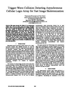
Fig. 5. ATLAS DataFlow performance testbed.
V. PERFORMANCE The final ATLAS DataFlow system requires simultaneous operation of RoI collection and event building. This section describes results obtained from a testbed capable of delivering approximately 10% of throughput as needed for the final ATLAS TDAQ DataFlow system. Performance measurements of individual DataFlow components have been made and show satisfactory results. These are described in detail in [11]. The testbed consists of 37 dual Intel Xeon 2.0–2.4 GHz CPU [12] rack-mountable PCs, interconnected via a fully switched gigabit Ethernet network. The operating system used was the CERN certified version of the Linux Redhat 7.2 distribution [13]. The software used compiler version gcc-2.95.2. Three kinds of traffic generators have been used to emulate large number of ROSs. These were based on custom-built FPGA boards, providing up to 128 ports; reprogrammed network interface cards, providing up to 16 ports; and ROS emulation and ROS prototype software applications running on PCs, to be shared with the PCs available in the testbed [10]. Fig. 5 shows a picture of the testbed as currently deployed in CERN. The FPGA-based network testers are identifiable on the right-hand side of the photograph through the 128 Ethernet cables connected to them. Other visible components are 1 and 4 U high rack-mounted PCs. A. RoI Collection The maximum rate at which an L2PU can collect RoI data depends on the size of the RoI, the number of ROSs that contribute data and the number of threads that collect RoI data in parallel on the same L2PU. Fig. 6 shows the inverse rate for an RoI of 16 kB collected as 1, 2, 4, 8, 16, or 22 slices of 16, 8, 4, 2, 1, or 0.8 kB, respectively. For this test, the L2PUs were completely dedicated to data collection and no CPU time was allocated for
Fig. 6. sizes.
Performance of RoI data collection for various combinations of RoI
algorithm processing. The plot shows that the time for acquiring RoI data is small compared to the execution time of selection software (currently aimed at 10 ms per event on average). B. Event Building The building of events is managed by the DFM and performed by SFIs requesting data from up to data sources, respectively, for bus-based readout (with aggregation of the data from up to 12 ROLs) and switch-based readout (without aggregation of data from individual ROLs) of the ROBIns. The scalability of the event building of 2.2 MB size events is shown in Fig. 7. In this test the number of SFIs in the set up was increased from one to eight and the corresponding event building rate was measured. It can be seen that the sustained event building rate increases linearly with respect to the number of SFIs in the system and that every additional SFI contributes to the overall system perHz. It should be noted that the results for formance by
BECK et al.: BASE-LINE DATAFLOW SYSTEM OF ATLAS TRIGGER AND DAQ
Fig. 7. Scalability of event building for bus-based and switch-based ROS scenarios.
eight ROLs/ROS were achieved with Ethernet flow control active, whereas flow control was not a necessity in the case of one ROL/ROS. VI. CONCLUSION Although the testbed necessarily is a scaled down version of the final system, individual components have been operated at rates similar to those expected in the final system. The primary aims of the 10% testbed are to demonstrate full functionality of the data collection in both the LVL2 and the EB subsystems simultaneously and to check for possible interference between the subsystems. The latter is especially important with respect to the choice to be made between a switch- or bus-based ROS. The testbed results have also been used to calibrate and validate computer models of components and systems [14]. This base-line DataFlow system and the performance figures reached on the prototype testbed meet the ATLAS requirements and are documented in the ATLAS High Level Trigger, Data Acquisition, and Controls Technical Design Report [11]. ACKNOWLEDGMENT The authors wish to thank the ATLAS Online Software community for providing a system and useful tools to control, configure, and operate large-scale distributed testbed setups. H. P. Beck, C. Haeberli, and V. Perez Reale are with the Laboratory of High Energy Physics, Bern University, 3012 Bern, Switzerland (e-mail:
[email protected]). S. Gadomski is with the Laboratory of High Energy Physics, Bern University, 3012 Bern, Switzerland, on leave from Henryk Niewodniczanski Institute of Nuclear Physics, 30059 Cracow, Poland. M. Abolins, Y. Ermoline, and R. Hauser are with the Department of Physics and Astronomy, Michigan State University, East Lansing, MI 48824-2320 USA. A. Dos Anjos and M. Losada Maia are with Instituto de Fisica, Universidade Federal do Rio de Janeiro, COPPE/EE, BR - 21945-970 Rio de Janeiro, Brazil. H. Boterenbrood, P. Jansweijer, G. Kieft, and J. Vermeulen are with NIKHEF, Amsterdam. M. Barisonzi is with NIKHEF, Amsterdam, and also with the Universiteit Twente, 7500 AE Enschede, The Netherlands. M. M. Beretta, M. L. Ferrer, and W. Liu are with the Laboratori Nazionali di Frascati dell’ INFN, 00044 Fracasti, Italy. R. Blair, J. Dawson, and J. Schlereth are with the Argonne National Laboratory, Argonne, IL 60439 USA.
475
J. A. Bogaerts, M. D. Ciobotaru, E. Palencia Cortezon, B. Di Girolamo, R. W. Dobinson, D. Francis, S. M. Gameiro, P. Golonka, B. Gorini, M. Gruwe, S. Haas, M. Joos, E. Knezo, G. Lehmann, T. Maeno, L. Mapelli, B. Martin, R. McLaren, C. Meirosu, G. Mornacchi, I. Papadopoulos, J. Petersen, P. de Matos Lopes Pinto, D. Prigent, R. Spiwoks, S. N. Stancu, L. Tremblet, and P. Werner are with CERN, CH-1211 Geneva, Switzerland. D. Botterill and F. J. Wickens are with Rutherford Appleton Laboratory, Chilton, Didcot OX11 OQX, U.K. R. Cranfield and G. Crone are with the Department of Physics and Astronomy, University College London, London WC1E 6BT, U.K. B. Green, A. S. Misiejuk, and J. Strong are with the Department of Physics, Royal Holloway and Bedford New College, University of London, Egham TW20 0EX, U.K. Y. Hasegawa is with the Department of Physics, Faculty of Science, Shinshu University, Matsumoto-shi, Nagano 390-8621, Japan. R. Hughes-Jones is with the Department of Physics and Astronomy, University of Manchester, Manchester M13 9PL, U.K. A. Kaczmarska, K. Korcyl, and M. Zurek are with Henryk Niewodniczanski Institute of Nuclear Physics, 31342 Cracow, Poland. C. Hinkelbein, A. Kugel, M. Müller, and M. Yu are with Lehrstuhl für Informatik V, Universität Mannheim, Mannheim D - 68131, Germany. A. J. Lankford and R. Mommsen are with the University of California, Irvine, CA 92697-4575 USA. M. J. LeVine is with Brookhaven National Laboratory (BNL), Upton, NY 11973 USA. Y. Nagasaka is with the Faculty of Engineering, Hiroshima Institute of Technology, Hiroshima 731-5193, Japan. K. Nakayoshi and Y. Yasu are with KEK, High Energy Accelerator Research Organization, Tsukuba-shi, Ibaraki 305-0801, Japan. M. Shimojima is with the Department of Electrical Engineering, Nagasaki Institute of Applied Science, Nagasaki 851-0193, Japan. H. Zobernig is with the Department of Physics, University of Wisconsin, Madison, WI 53706 USA.
REFERENCES [1] “ATLAS detector and physics performance Tech. Design Rep.,” ATLAS Collabor., CERN/LHCC/99-14, 1999. [2] S. Armstrong et al., “Algorithms for the ATLAS high level trigger,” IEEE Trans. Nucl. Sci., pp. 367–374, June 2004. [3] The S-Link Interface Specification, O. Boyle, R. McLaren, and E. van der Bij. [Online]. Available: http://edms.cern.ch:8001/ceder/ doc.info?documnet_id=110 828 [4] Design specification for HOLA, A. Ruiz and E. van der Bij. [Online]. Available: https://edms.cern.ch/document/330 901 [5] B. Green, G. Kieft, A. Kugel, M. Mueller, and M. Yu, “ATLAS trigger/DAQ readout-buffer (RoBIn) prototype,” IEEE Trans. Nucl. Sci., pp. 465–469, June 2004. [6] H. P. Beck, R. W. Dobinson, K. Korcyl, and M. LeVine. ATLAS TDAQ, a Network-Based Architecture. [Online]. Available: http://atlas.web.cern.ch/Atlas/GROUPS/DAQTRIG/DataFlow/DataCollection/docs/DC-059/DC-059.pdf [7] A prototype RoI builder for the second level trigger of ATLAS implemented in FPGA’s, M. A. Abolins, R. E. Blair, J. W. Dawson, Y. Ermoline, W. N. Haberichter, and J. L. Schlereth. [Online]. Available: http://doc.cern.ch/archive/electronic/cern/others/ atlnot/Note/daq/daq-99-016.pdf [8] C. Haeberli et al., “ATLAS-TDAQ DataCollection software,” IEEE Trans. Nucl. Sci., pp. 585–590, June 2004. [9] H. P. Beck and C. Haeberli. Message flow: high-level description. [Online]. Available: http://atlas.web.cern.ch/Atlas/GROUPS/ DAQTRIG/DataFlow/DataCollection/docs/DC-012/DC-012.pdf [10] M. LeVine et al., “Validation of the ATLAS trigger/DAQ network architecture using hardware data emulators,” IEEE Trans. Nucl. Sci., pp. 539–544, June 2004. [11] “ATLAS High Level Trigger, Data Acquisition and Controls Tech. Design Rep.,” ATLAS Collabor., CERN/LHCC/2003-022. [12] Intel Xeon Processor [Online]. Available: http://www.intel.com/xeon [13] CERN Linux Pages [Online]. Available: http://linux.web.cern.ch/linux/ [14] R. Cranfield, P. Golonka, A. Kaczmarska, K. Korcyl, J. Vermeulen, and S. Wheeler, “Computer modeling the ATLAS trigger/DAQ system performance,” IEEE Trans. Nucl. Sci., pp. 532–538, June 2004.