The Cell Broadband Engine as an example of a multithreaded embedded processor Gregor Burger
[email protected]
Seminar Embedded System Design, WS 2007/08 Institute of Computer Science, University of Innsbruck February 6, 2008 This Seminar Paper describes the fundamentals of multi-threaded processors. What reasons drove the development of such processors. Whats the gain in processor design of such an multi-threaded architecture. After the short introduction in multi-threading the paper goes on to describe the Emotion Engine which is the technical predecessor of the Cell Broadband Engine. It is described where the Emotion Engine is similar to the Cell Broadband Engine and where they are different. The two main topics of the paper are the architecture of the Cell Broadband Engine and how to programm the Cell Broadband Engine. In the architectural part all components of the processor are described. Special detail goes into the eight Synergistical Processing Elements. In the Programming part the Software Developement Kid is described and how to use the SDK to develop fully tuned Cell Broadband Engine programms. The last part of this paper shows a Realtime Terrain Rendering system as an realworld example for the Cell Broadband Engine. It shows how to work with the ressources provided by CPU, how to split up the work and how to communicate between the parts of the system. In the Conclusion the main design ideas are reviewed and statet why those decissions for the implementation of this design were made.
1
1 Introduction After describing what Multi-threading and its advantages the introduction goes on with some historically aspects about the Cell Broadband Engine (CBE). The Emotion Engine (EE) is describes as the historicall predescessor of the CBE. After introducing the EE a short development timeline is presented with some fiscal facts about the development of the CBE.
1.1 Multithreading Various techniques were developed to increase the efficiency of processors. If we speak about efficient processor designe in the aspect of multi-threading we mean that the ressources on the processor are used efficiently to increase the performance of the processor. The main aspect of being efficient is doing things in parallel. Pipelining was the first step into this direction. Pipelining can best be described with the assembly line analogy. In an assembly line a big task, like building a car, is broken up into small subtask done by different people. Each subtask is done as efficient as possible. After a subtask is done the product is put forward to the next stage of the assembly line. Pipelining is the same principle but done in a processor. The instructions are split up into small subtask which can be done by different parts of the processor. [PHB+ 05] Figure 1 shows a pipeline with five stages in which the instructions are worked on in parallel. The individual parts of the processor don’t need to wait before the others are finished. In a best utilized pipeline all the units 1 have something todo all the time.
Figure 2: Superscalar MIPS pipeline (source [Wik08d])
threads are concurrently served by one Central Processing Unit (CPU). This can happen in three different ways: 1. fined grained, 2. graose grained and 3. symultaneous multithreading (SMT). The first two types of multithreading are called interleaved multithreading because of interleaved issueing of multiple instruction from different threads. There is also a third type of multithreading, not discussed in this paper, name chip level multithreading (CMT) which integrates to ore more processor (each running a single thread) on one chip. This type is also known as multicoring. [Wik07] 1.1.1 Fine Grained Multithreading
In fine grained multithreading (FMT) a thread change happens after each instruction is finished. The thread change is done in a round-robin fashion where stalled Figure 1: MIPS Pipeline with five stages [Wik08c] threads are skipped. This kind of multithreading covers long an short pipeline stalls. The disadvantage is that the more threads interleaved on one chip the slower the [Str07] single threads get. Theres also a special device needed If we go one step further an execute two pipelines to handle the fast frequent changes of threads. FMT is in parallel we speak about Superscalarity. This kind used in Sun’s Ultra T1 processors. [Str07] of pareallelism is called Instruction Level Parallelism (ILP). In this Superscalar design instructions are issued from a sequential stream. The hardware dynam- 1.1.2 Groase Grained Multithreading ically checks for dependencies and assures integrity of In groase grained Multithreading (GMT) a thread the data. [Wik08d] Figure 2 shows a 2-fold superscalar change only happens when executing the current thread pipeline. causes some long latency events like page faults or L2 The next step of parallelization is Thread Level Parcache misses. As thread changes only happen on long allelism (TLP). TLP is the main idea behind multilatency events small latency events are therefore igthreading. In TLP not only instructions from a senored. GMT does not slow down single threads. GMT quential stream are issued into the pipeline, multiple is used when the time to start a thread is much higher 1 Each step in a pipeline is tied to a special unit than the time of a stall. [Str07, Wik07]
2
troller. A schematic description of the processor and the additional components used in the PS2 are shown in Figure 4. The EE is very similar to the CBE in that it has a very fast bus which connects the different units of the EE. The bus runs at 3.2 GB/Sec. Every unit of the processor can run in parallel and independently of each other. The two VUs process up to four single instruction multiple data (SIMD) instructions in parallel. These two VUs in combination with the DMA controller and the memory controller can be seen as the grandparents of the synergistic processing elements (SPE) on the CBE. [Rus03, Wik08b, Wil07]
(a) Fine Grained
(b) Groase Grained
Figure 3: Interleaved Multithreading
Figure 4: Schema of the Emotion Engine used in the PS2
1.1.3 Symultaneous Multithreading The main idea behind SMT is to combine TLP and ILP. Instead of one thread several threads are executed at the same time, so that instructions from the threads are issued in each clock cycle. In SMT processor the complete register set and interrupt controller are duplicated so that the threads can access them simultaneously. Functional units and caches are shared among the threads. [Str07] The operating system (OS) sees two seperate processors. This has impacts on the software which runs on SMT processors. To fully utilize the threads available on these processors the software must also run several threads 2 . So in SMT the software needs to be adapted to fully exploit the SMT capabilities of these processors. [Str07, Wik07]
2 History 2.1 Emotion Engine (Sony, Toshiba) The Emotion Engine was used in the Sony Playstation 2 (PS2). It has a MIPS core, two vector processing units (VU), a 10 channel dma and a memory con2 Software-threads
started by the OS is a different concept than hardware threads in processors.
2.2 Development History The CBE is a joint effort of Sony Toshiba and IBM known as the STI alliance. The design and first implementation of the CBE were carried out by the STI Design Center in Austing, Texas. It took STI over four years, US$ 400 Million and 400 engineers to build and design the processor. The CBEs first commercial use was in Sonys Playstation 3 Game console. IBM uses the Cell as CPU for its newer Bladeservers. Toshiba reported to use the Cell processor in its HDTV products. They use the Cell to support better upscaling algorithms which current TVs or DVD players can’t handle. [Smi08]
3 Architecture In this paper main attention is given to the three functional units which make this processor unique an interresting. The three units are: 1. the Power Processing Unit (PPU), 2. the Synergistic Processing Units (SPU) 3. and the Memory Flow Controller (MFC) which belongs to a SPU.
3
The three components are connected via the Element Interconnection Bus (EIB). A typical configuration of a CBE is one PPU and eight SPUs. Sony uses processor where seven out of the normal eight SPUs are functional to increase the yield of the manufacture. In Figure 5 a typical configuration is shown. A PPU has a L2 and L1 cache. The SPU hast just a Local Store (LS) which is a high speed memory in the fashion of a programmable cache.
• • • • •
fetch, decode, branch, issue and completion instructions,
2. an Fixed point Unit (XU) for • load/store • and fixed point instructions 3. and an vector scalar unit (VSU) for vector and floating point instructions. [IBM07b]
Figure 5: CBE Schema with one PPE and eight SPEs
3.1 The Power Processing Element (PPE) The PPE is a standard compliant 64 bit PowerPC processor. It follows the definitions in the PowerPC Architecture Books I-III. Additional to the standards described in the Books the PPE requires some optional features of the Books. The PPE acts and feels like a standard PowerPC processor but its a very simplified an stripped down version to make place for the eight SPEs. The PPE only supports a 23 stage deep pipeline with no reordering of instructions. It is a multithreaded processor with two simultaneously threads. The PPE has a standard cache hierarchy with a 32 KB first level cache for data and instructions anda 512 KB second level cache. The PPE has a Replacement Management Table (RMT) which allows the programmer to lock certain regions of the cache to prevent overriding. This RMT gives the programmer much more controll over the cache and the caching behaivours. As mentioned earlier the PPE is a multithreaded architecture with two simultaneous threads. They appear as two indipendent processing units. All architecture states are duplicated to perform interleaved instruction issuing. The processor is two-way with a shared dataflow. A schematic overview can be seen in Figure 6. The PPE has three logical units: 1. An Instruction Unit (IU) for
4
Figure 6: The schema of a PPE
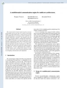
3.2 The Synergistic Processing Element (SPE) Beside the PPE the CBE has eight Synergstic Processing Elements (SPE) for processing data. The main purpose of these SPEs is raw data processing. They lack certain functionality which allows them to do normal operating system tasks like Virtual Memory (VM). They also have no direct acces to the main memory installed and very limited interrupt support. The intend of these processors is to fill the gap between General Purpose Processors (GPP) and Special Purpose Processors (SPP). SPEs are much more flexible in that they can be programmed freely instead through APIs like OpenGL in the case of Graphics Processing Units (GPU). The concentration of these SPEs is data processing as fast as possible. Main workloads of the SPEs are influenced by the corporations which designed the processor. Sonys main interrest lies in accelerating games and applications which run on the Sony Playstation 3 entertainment system. These applications include: • Artificial Intelligence (AI) calulations,
refer-
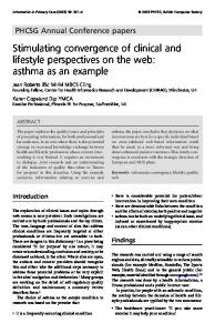
• animations (particle, large scale characters, etc..), SPE can calculate other stuff in parallel. In some applications like the Terrain Rendering Engine described • physics calculations like colision detection, in chapter 5 on page 8 the total wait time for memory • preprocessing vertex data to cut the data going only adds up to 1%. The MFC can be controlled from its SPU through into the GPU and channels. Other SPEs or the PPE can control a particular MFC through Memory Maped Input Output • ingame audio processing. (MMIO) registers as can be seen in Figure 8. ChanFigure 7 shows the schema of an SPE. Its a 128-Bit nels are unidirectional message passing interfaces suptwo-way RISC core 3 with a single register file including porting 32 bit messages or commands. Channels are 128 128-bit registers. The processor has a 256-Kb local- used for enqueing DMA commands, monitoring SPU store for data and instructions. The localstore can be events, performing Inter Process Communication (IPC) seen as a programmable cache. The processor can ac- via mailboxes ore signals and other functionalities. cess the localstore throuch load and store instructions. Data from the mainstorage can only be transferrd into localstore through DMA transfers.
Figure 7: Schema of a SPE [Wik08a]
3.3 The Memory Flow Controller (MFC)
refer-
Figure 8: Schematic communication of an SPE
As mentioned earlier mailboxes are special devices for IPC. They are special queues for messaging between SPEs and the PPU. Data written to one of the three mailboxes can be read by any other processor via the corresponding MMIO register. There are two mailboxes for outgoing messages and one for incoming messages. One of the outgoing mailboxes is able to interrupt the PPU so that polling the mailbox can be avoided. Each mailbox can be controlled by the corresponding MMIO register or by the special mailbox channels from inside the SPU. Beside the mailboxes every MFC has another two signals. Signals are often used for buffer completion messages. They only support inbound messages and the SPE can only read the signals. This readonly mechanism allows the SPE to poll, block or setup an interrupt for notification. Other processors can read and write the signals through the corresponding MMIO registers. A read through one of the signal-channels clears the signal.
The Memory Flow Controller (MFC) is the peace of hardware which is responsible for transfering memory to/from localstore to/from mainstorage and to handle all the communications between the SPEs and between SPEs and the PPE. Each SPE has a MFC. The MFC connects the SPE to EIB and handles therefore the communication with the rest of the processor. The transfer of data between the localstore and the mainstorage is somehow unique. The SPE can’t directly acces the mainstorage. Data is transferred from localstore to the mainstorage an back via DMA instructions. There is no other possibility to do this. Since the memory latency is the main driving factor in application performance these days the designers of the CBE tried to get over these problems through forced DMA transfers between the localstore and mainstorage. The setup of a DMA takes the SPE a few cycles whereas a cache miss on a normal system causes the CPU to stall to up to thounsands of cycles. Instead of waiting for memory the SPE allows to make asynchronous DMA 3.4 Architecture Conclusion transfers. While waiting for the memory to arrive the As the previous chapter has shown, the CBE Archi3 The reader may notice the similarity to the EE presented in tecture is a radical change in how the processor is dechapter 2.1 on page 3. signed. Nine processors on one chip, a processor which
5
TODO reference
cannot directly access main storage and two completely different types of processors for two different types of usages on one chip is a complete new and revolutionary design. The reason for this radical design is that memory latency has gone up several hundredfold in the last 20 years. Application performance is determined by the memory latency bottleneck rather than peak computing capability. A cache miss on a conventional machine stalls the computation for several 100 CPU cycles compared to the few cycles of a DMA setup on the CBE. The CBE tries to overcome three performancelimiting walls:
programming the Cell 4 is harder than programming for other plattforms like the Personal Computer (PC). On the other side IBM says programming the Cell is as hard as programming any ohter platform. And indeed the Cell is basically a PowerPC processor and therefore every application written in a portable way may run immediately on the Cell. Both are right in that porting to the Cell may be easy but getting the best performance on it may require to break currently learned and trained ways of programming. But IBM does a good way in supporting the programmers through the IBM SDK for Multicore Acceleration.
1. power-limitation wall: 4.1 The IBM SDK for Multicore overcoming the power-limitation wall was achieved Acceleration by having two different types of processors optimized for different types of applications. First a The IBM SDK for Multicore Acceleration (further reprocessor optimized to run operating system and ferred to as SDK) is basically a toolchain for the linux control sensitive code, the PPE. And second a pro- plattform. It includes: cessor optimized to run compute-intensive applications. This design allowed higher performance for • A GNU tool chain optimized for the CBE, less power. • an IBM XL C/C++ compiler, 2. memory-limitation wall: • the IBM Full-System Simulator, as previous described current application performance is dominated by the memory latency of • a system root image for the simulator (Fedora 7), cache misses. The CBE overcomes this wall by having asynchronous self controlled cache manage• a linux kernel optimized for the CBE, ment. Asynchronous DMA calls allow the pro• the Cell BE libraries, grammer to request memory in advance and continue with other calculations before the requested • prototype libraries, data arrives. 3. frequency-limitation wall: conventional processor design try to get higher frequencies by deepening the instruction pipeline. The CBE design tries to avoid these power intensive pipelines by otimizing the processor for high parallel and specialized processors. The PPE allows two threads run simultaneously. The SPEs allow with its large register files several instructions in parallel. Together these results in much more computing power. [IBM07a]
• performance support libraries and utilities and • and IBM Eclipse IDE for the SDK The SDK is free for evaluation use and can be optained through http://www.ibm.com/ developerworks/power/cell/. The SDK can be used in Fedory Core 7 and RHEL 4. Its also possible to use the SDK through a foreign OS installion on the PS3. IBM also provides a commercial version for its Unix Machines.
4.2 Programming Models
As previous mentioned programming the cell needs some training. This section tries to summarize some of the aspects which a programmer needs to cope with when programming the CBE. A programmer has the choice of programming in As the CBE was embedded in the PS3 programmers C/C++ or Fortran which are available through the needed to optimize games for the CBE. The radical SDK. The various SIMD instructions which allow parchanges described in chapter 3.4 on the previous page allel processing of data are available through special resultet in a change of how programms need to be writintrinsic header files. These intrinsics are wrapper ten. Game developers needed to learn heavy parallel 4 programming and how to exploit the performance of Game developers refer the Cell Broadband Engine to just the Cell the eight SPEs. This facts drove some rumors that
4 Programming the Cell Broadband Engine
6
functions around the inline assembler SIMD instructios. SIMD programmer need to care about the layout of the data on which they would like to base their calculations. One can choose between a structure of array or an array of structure layout shown in Listing ?? on page ??. Both have their pros and cons. SIMD programmer must follow two principle objectives while doing their work: 1. extract parallelism from loops and basic blocks and 2. satisfy constraints on data alignment, data-size conventions, data-stride and layout. Listing 1: SIMD layouts union { coordinate { float x , y , z , w; } coordinate ; vector float vertex ; } array [ ] ; struct
struct { float float float float } vertices ;
x[]; y[]; z []; w[ ] ;
Beside the involved SIMD programming a developer needs to be aware of the heavy multi-threaded and the implying synchronizations needed between the threads. These conventions are used by Cell programmer to distinguish the highly partitioned parts of a typical Cell programm:
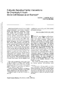
2. If the code runs the programmer needs to develop a threading model. Meaning what can be run in different threads. This also includes simple Multithreading on the PPU. 3. The next step is to bring the PPU threads onto the SPU. This also includes the development of a communication protocol between the CPUs as well as how the memory can be split up to fit into the limited localstore. 4. The next step is to use the SIMD units of the PPU as well as that of the SPU. A data layout must be choosen and the memory boundarys must be satisfied. Step three of the previous described development plan is by far the hardest. Because of this fact this paper tries to describe what models can be used to utilize all the available SPUs. IBM describes various models in their SDK Programming Manuals but there are many more. Some of the highlevel models are described in this paper. Figure 9 shows an overview of the models most commonly used. We can distinguish between two different models by the way the model uses the PPU. SPUCentric models tend to be very rare and thats why they aren’t discussed in this paper. They have the attribute of just calculating stuff on one or more SPUs without ever using the PPU. PPU-Centric models on the other side use all the available ressource on the Cell and the work is coordinated by the PPU.
main thread Linux thread running on the PPU. Spawns CBE Tasks. CBE task One or more Linux threads running on the PPU or SPUs. SPU thread Thread running on the SPU. Has its own SPU context which includes:
Figure 9: Overview of the Models
• 128 x 128 bit register file, • program counter and • MFC Command Queues.
Two of the famouse PPU-Centric models are shown in Figure 10 on the following page. One is the Multistage Pipeline Model in which data is given around PPU thread Linux thread running on the PPU. by the different processors. Each processor has its own IBM describes a preferred way of developing and stage and therefore its own kind of work. On the other porting to the Cell. The following steps allow a fast hand we have the Parallel Stage Model in which on way to get a difficult algorithm running and fully op- each SPU the same algorithm runs. Choosing the right model is dependen on the algotimized on the Cell. In the following developing also rithms used, the memory usage of the algorithms and means porting to the cell. so on. Depending on a particular problem the program1. The first step is to make the code run on the mer must choose different models. The two models dePPU. Thats just classical programming without scribed should just show how the SPU can be used to any SIMD or SPU code involved. A port to the split up the work. A handfull of models are described PPU is in most cases a recompile of the code. in the CBE Programming Guide[IBM07c].
7
Figure 10: PPU Centric Models
5 TRE: Cell broadband optimized real-time ray-caster This section describes the TRE rendering system which uses the Cell to render a terrain in realtime. After a short introduction into ray-tracing and the simplified version ray-casting used in this application the algorithm used to render the terrain will be described. A short description on how the work was divided and how the data was transfered through the CPUs is given. At the end results are presented which show how much there is to gain from the Cell.
Figure 11: Ray-tracing with primary and secondary shadow rays
intersection tests. Because of these high numbers raytracing is typically used to render the images off-line. Real-time rendering requires at least 24 pictures per second to get the impression of a smooth movie.
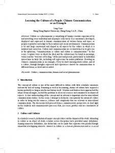
5.1 Ray-tracing Ray-tracing is a rendering algorithm for producing photorealistic 3D images. Every 3D computer image not generated in realtime, like in games and realtime animations, is done using some kind of a raytracing algorithm. Ray-tracing at its heart follows a physical model to get images from an virtual environment. A ray-tracer follows rays from the eye-point through every pixel in the image searching for intersections with objects in the virtual scene to be rendered. After the first intersection additional rays are traced to calculated global illumination effects, shadows, reflection and refractions. Figure 11 shows the primary ray from the eye to the green ball and the secondary rays which calculate shadows and indirect illumination. As one may imation ray-tracing is an really computing intensive application. In its simplest, not optimized form with just primary rays a 720p image has
Figure 12: Real-time ray-traced car on 4 CBEs.
Various algorithms exist for speeding up the raytracing algorithms. In the Terrain Rendering Engine described in the paper [MFT05] they used a technique called Vertical Ray Coherence (VRC) [LS97] to speed up the rendering of the terrain. The algorithm uses vertical cuts which are perpendicular to the plane of 1280 ∗ 720 = 921600 the height map shown in figure 13 on the facing page. The Application is built as a client server. The client pixels. Through every pixel a ray gets shot and needs runs on a cheap device which has a framebuffer and into be checked against intersections of all objects in the put devices. The server runs on a dual SMP CBE with scene. With a typical scene of 1 Gigabyte RAM. The server scales to as many SPEs available. Three threads run on the PPE. The first 1000000 one is responsible for frame preperation and SPE work communication. The second and third share a procesobjects we have sor thread affinity and do the communication work like 921600000000
8
2.0 GHz Apple G5 1GB memory 3.2 GHz UP Cell 512MB memory 3.2 GHz 2-way SMP Cell 1GB memory
0.6 30 58
Table 1: tablecaption The PPE code got just basic tuning. The ray-kernel running on the SPE got most of the tuning time. Tuning included code/data footprint and synchronization tuning. For the benchmark the folling datas were used: • 1280x720 (720p) output image • 7455x8005 map size Figure 13: Vertical cuts
• 2-32 samples per pixel (dynamic) The results are shown in table 1.
frame delivery and client communications. Most of the work is done on the SPEs. To fully scale over all the available SPEs the TRE uses a three stage deep rendering pipeline shown in figure 14. Prep Frame is responsible for dividing up the work based on the vertical cuts and delivering the results to the SPEs. Render Frame is the work thread where each SPE decomposes its vertical cut into rays, calculates the intersection points, shades the samples and stores the result into an accumulation buffer. Encode Frame runs on a reserved SPE which encodes the accumulation buffer for rendering on the client device. After the encoding the SPE can be repurposed to run a Render Frame thread.
Figure 14: The three stage deep image pipeline
The descriped pipeline allows the SPEs to work as independent as possible from the PPE. The PPE just send descriptions what to do to the SPEs. The data is brought into localstore via DMA requested by the SPE so that data doesnt stream through the PPU. The ray-kernel running on the SPEs is heavily optimized to the Cell. It has a double buffered fetch and compute phase to fully exploit parallel DMA executions. The optimizatins in the ray-kernel result in just 1% of wait time for data.
5.2 Results The algorithm was initially implemented on a Apple G5 computer which is used as a base messearument.
9
References [IBM07a] IBM. Cell BE Programming Tutorial, v3.0 edition, 10 2007. [IBM07b] IBM. Cell broadband engine architecture, 10 2007. [IBM07c] IBM. Programmer’s Guide to the IBM SDK for Multicore Acceleration, v3.0 edition, 10 2007. [LS97]
Cheol-Hi Lee and Yeong Gil Shin. A terrain rendering method using vertical ray coherence. The Journal of Visualization and Computer Animation, 8(2):97–114 (or 97–112??), 1997.
[MFT05]
B. Minor, G. Fossum, and V. To. Tre: Cell broadband optimized real-time ray-caster. Proceedings of GPSx, 2005.
[PHB+ 05] David A. Patterson, John L. Hennessy, Arndt Bode, Wolfgang Karl, and Theo Ungerer. Rechnerorganisation und -entwurf. Spektrum Akademischer Verlag, 3. a. edition, September 2005. [Rus03]
James Russell. Introduction to playstation 2 architecture. In Kriconf 2003, 2003.
[Smi08]
Tony Smith. Toshiba demos cell-equipped hdtv, 01 2008.
[Str07]
Prof. Dr. A. Strey. Advanced computer architecture. Course, 10 2007.
[Wik07]
Wikipedia. Simultaneous multithreading — wikipedia, the free encyclopedia, 2007. [Online; accessed 28-January-2008].
[Wik08a] Wikipedia. Cell (prozessor) — wikipedia, die freie enzyklop¨adie, 2008. [Online; Stand 30. Januar 2008]. [Wik08b] Wikipedia. Emotion engine — wikipedia, the free encyclopedia, 2008. [Online; accessed 28-January2008]. [Wik08c]
Wikipedia. Instruction pipeline — wikipedia, the free encyclopedia, 2008. [Online; accessed 28January-2008].
[Wik08d] Wikipedia. Superscalar — wikipedia, the free encyclopedia, 2008. [Online; accessed 28-January-2008]. [Wil07]
10
Andrew Williams. Introduction to playstation 2 architecture. Games Hardware, Architecture and Peripherals, 2007.