The Central Guardian Approach to Enforce Fault Isolation in the Time-Triggered Architecture∗ G¨unther Bauer
Hermann Kopetz
Wilfried Steiner
Institut f¨ur Technische Informatik Vienna University of Technology Treitlstr. 3/3/182.1 A-1040 Vienna, AUSTRIA E-mail:
[email protected] Abstract This paper discusses measures to make a distributed system based on the Time-Triggered Architecture resistant to arbitrary node failures. To achieve this, the presented approach introduces a central guardian as part of the interconnection network. This guardian acts as a supervising unit to node computers by checking for fault hypothesis compliance at their respective network interfaces. By implementing appropriate algorithms the guardian is able to transform failure modes of nodes that cannot be tolerated by the fault hypothesis of the TTP/C protocol. This transformation ensures that – at the interface to correct nodes – even an arbitrarily faulty node will then be compliant to the fault hypothesis of the TTP/C communications protocol.
1 Introduction The Time-Triggered Architecture (TTA) is a distributed computer architecture for highly dependable real-time systems. The core building block of the TTA is the communications protocol TTP/C. This protocol has been designed to provide non-faulty nodes with consistent data despite the presence of faulty nodes or a faulty interconnection network channel. To achieve consistency the protocol assumes that a fault is either a reception fault or a consistent send fault of some node. Although the communications protocol of the TTA uses this rather optimistic failure mode assumption, the TTA can isolate and tolerate a broader class of faults. This is possible by making intensive use of the static knowledge present in a TTP/C-based distributed computer system. This off-line available knowledge allows to build interconnection networks which transform arbitrary failure modes of nodes ∗ This document is part of deliverable D1.1 of the IST Project Next TTA (project no. IST-2001-32111). It is a preliminary draft version intended to solicit feedback and subject to the same security and distribution policy as deliverable D1.1.
into failure modes the communications protocol can deal with. This paper will discuss a promising new approach to transform failure modes in TTP/C-based systems utilizing a star topology interconnection network: the central guardian [7, 2]. Regardless of the number of nodes, a TTA cluster only needs two central guardians. Thus, as opposed to a node-local guardian required n times in a cluster comprising n nodes, the design of a central guardian is less constrained by manufacturing costs. This allows for sophisticated algorithms and as much independence from the node computers as the system integrator is willing to spend (e.g., with respect to power supply). In particular, a smart central guardian will be able to isolate slightlyoff-specification (SOS) faults of TTA node computers. A SOS-faulty component is only marginally faulty at its interface to other components and appears correct to some of them but faulty to others (thus, a SOS fault is a Byzantine fault [10]). SOS faults cause fault propagation between node computers in bus-based TTA networks [1]. The remainder of the paper is organized as follows: Section 2 gives an introduction to the Time-Triggered Architecture, its core communications protocol TTP/C, and its fault tolerance capabilities and fault hypothesis. In Section 3 the tasks of a guardian in general and of a central guardian in particular are discussed. Sections 4 and 5 present measures needed to isolate arbitrary node faults at the physical line interface and the semantic interface of the communications protocol, respectively. A summary of the services of the guardian and the revised fault hypothesis of a central-guardian-based star coupler TTP/C cluster is provided by Section 6. Finally, the paper ends with a conclusion in Section 7.
2 Architecture Overview The Time-Triggered Architecture (TTA) is a distributed computer architecture for the implementation of dependable real-time systems. Fundamental to the TTA is the availability of a global time of known precision in
each node of the distributed computer system. Fault tolerance is achieved at the cluster level by replicating the nodes within a cluster and by replicating the communications channels between the nodes. A TTA cluster consists of a set of TTA nodes connected by a replicated interconnection network. A TTA node computer comprises a host computer and a communications controller with two bi-directional communication ports. Each of these ports is connected to an independent channel of a dual-channel interconnection network. Via these broadcast channels the nodes communicate using the service of the communications controller executing the time-triggered communications protocol TTP/C, which constitutes an integral part of the TTA.
2.1
nels, it considers the respective sender correct. A correct receiver will consider a frame correct if it meets all of the following requirements: • transmission of the frame starts and ends within the temporal boundaries of its TDMA slot • the signal constituting the frame on the physical layer obeys the line encoding rules • the received frame passes a CRC check • sender and receiver agree on the distributed state of the TTP/C protocol (i.e., the C-state) It does not matter if the sender is in fact correct (as judged by an omniscient observer) or what faulty receivers conclude. If a node receives a correct frame, it assumes that the contents of the frame are authentic and that sender and receiver agree on the distributed state of the communications system, i.e., the controller state (Cstate). The C-state consists of the membership, the global time the frame broadcast was started at, and the number of the current TDMA slot. To test C-state agreement when an N-frame (which contains solely user data) is received, the CRC check mentioned above is performed on the frame data concatenated with the local C-state (extended CRC check [8]). If the resulting CRC checksums are identical at sender (i.e., the checksum transmitted with the frame) and receiver, the receiver assumes that it maintains the same C-state as the sender. Alternatively, when an I-frame or an X-frame is received, the C-state data transmitted with the frame are compared to the receiver-local view of the C-state. In any case a node can only succeed in broadcasting frames if it maintains a correct C-state (i.e., the same C-state as the receivers). To allow for integration of nodes into an active cluster, some nodes of the cluster periodically broadcast their respective C-state in I-frames or X-frames. Nodes willing to integrate can learn membership, global time, and the actual position within the global communications pattern from the C-state. Thus, the node is enabled to participate in communication after having received an I-frame or an X-frame.
The TTP/C Communications Protocol
The TTP/C protocol implements broadcast communications that proceeds according to an a priori established time-division multiple access (TDMA) scheme. This TDMA scheme divides time into slots each being statically assigned to a particular node. During its slots the node has exclusive write permission to the interconnection network. The slots are grouped into rounds: in the course of a (TDMA) round every node is granted write permission in exactly one slot. Furthermore, nodes always send in slots having the same relative position within a round; finally, the slots assigned to a particular node have the same length in each round. A distributed fault-tolerant clock synchronization algorithm establishes the global time base needed for the distributed execution of the TDMA scheme. A cluster cycle comprises several TDMA rounds and multiplexes the slots assigned to a node in succeeding TDMA rounds between different messages produced by the node (this is similar to the TDMA round, which multiplexes the communications channels between several nodes). Every node has knowledge – stored in read-only memory – of the complete communications pattern (and not only of the slots assigned to itself). These data are called message descriptor list (MEDL) and allow nodes to know a priori the types of messages being sent or received. Thus, there is no need for transmitting the sender IDs or message IDs explicitly. TTP/C messages are called frames and the protocol defines three types of frames: normal frames (N-frames) carry user data. Initialization frames (I-frames) carry protocol-specific state information that allows nodes to integrate into an operational cluster. Finally, extended frames (X-frames) contain both user data and protocol state information. The type of a frame to be transmitted in a particular slot of the TDMA round is also stored in the MEDL. In addition – to allow for node integration – frames carry an identifier bit in a frame header. By periodic examination of frame states the protocol establishes a membership service: if a node receives a correct frame [8] on either of the communications chan-
2.2
TTP/C Protocol Fault Hypothesis
In the following paragraphs we will introduce the fault containment regions [6] of the TTP/C protocol. Further, we will provide definitions of correct fault containment regions and of types and frequency of faults that can be withstood by the protocol. Finally, we will define a minimum configuration needed to tolerate these faults. If a particular cluster meets the requirements imposed by the fault hypothesis, the protocol provides the following services to synchronized correct nodes: • atomic broadcast and consistent membership • global time base of known precision Π 2
• protection against faulty nodes, i.e., isolation of faults to within the respective fault containment region 2.2.1
ceived from some sender node s being correct at the interconnection network interface to all correct receiver nodes ri with a known maximum delay δ(c, s, ri ) provided that there is only a single sender. Strictly speaking, a correct channel will correctly deliver frames if no other node writes to the interconnection network for
Fault Containment & Correctness
The TTP/C protocol distinguishes between two types of fault containment regions:
γ(c, s) ≥ max(δ(c, s, ri )) ∀i
• node computers (comprising a host computer and a communications controller part) and
after a correct sender as completed frame transmission. γ(c, s) may be larger than the maximum transmission delay if a particular implementation of the interconnection network channels needs some time to “recover” from a previous transmission before being ready to relay another frame.
• channels of the interconnection network. A fault containment regions is supposed to fail as a unit. Distinct fault containment regions will fail statistically independently if the respective faults are covered by the fault hypothesis. Correctness of a node computer is determined by the correctness of its constituting parts: Correctness of the host computer and correctness of the communications controller. As for the host computer, correctness needs to be defined by the particular application and will not be discussed in this document. Correctness of a TTP/C communications controller again has two aspects (with respect to relevancy to the discussions of this paper): First, there is correctness as judged by an omniscient external observer. This includes – besides others – that the protocol algorithms are correctly executed, that the skew of the node-local hardware clock is bounded by a known drift rate ρ, that the node maintains correct configuration data (i.e., MEDL), and that the communications controller provides consistent data at the host interface and the communications network interface. Second there is correctness as perceived at the interconnection network interface of a node. This aspect is of particular importance to the discussions in this paper. As stated in Section 2.1, a sender node is considered correct by a receiver node if at least one of the frames it broadcasts in its sending slot passes the correctness checks at the receiver node. A node is said to be correct at the interconnection network interface if it provides a correct frame at the interface in its sending slot. Thus, a correct receiver node will consider a sender correct if the sender is correct on at least one of its replicated interconnection network interfaces (provided the respective channel is correct). Note, that correctness at the interconnection network interface is neither a necessary nor a sufficient condition for correctness of the respective node computer. If the cluster operates in a synchronous mode, an integrating node may be correct but not synchronized yet. Thus, the sending slot of the node may pass without the node broadcasting any frame. Conversely, a node may broadcast frames that meet all the correctness requirements of Section 2.1 but still be faulty. A correct channel c of the interconnection network will deliver identical and authentic copies of a frame re-
2.2.2
Node Faults
As for the frequency of node faults, the fault hypothesis of the protocol claims that 1. only one faulty node exists within the duration of a TDMA round 2. a node may become faulty only after any previously faulty node either has shut down or operates correctly again. With respect to the types of node faults, the TTP/C protocol assumes that 3. a transmission fault is consistent (i.e., if a faulty node broadcasts a frame on a correct channel, all receiving nodes will consistently consider the respective frame faulty or correct) 4. a node does not send data outside its assigned sending slots on both channels of the interconnection network 5. a node will never send a correct frame outside its assigned sending slots 6. a node will never hide its identity when sending frames. The fault hypothesis does not state anything about faults other than communications faults. Any fault of a node (even a reception fault) will either become manifest by a transmission fault of the affected node or will never be perceived by other nodes of the cluster. 2.2.3
Network Faults
With respect to the frequency of faults of a channel, the fault hypothesis states that 7. only one channel is faulty during a TDMA slot As to the types of interconnection network faults it must be guaranteed that
3
8. a channel does not spontaneously create correct frames
Guardian
9. a channel will deliver a frame either within some known maximum delay or never 2.2.4
output to system
input from system
Single Faults & Minimum Configuration
The TTP/C protocol promises to provide its consistent frame delivery and membership service even in the presence of faults provided that at most one component happens to be faulty in a particular slot. To achieve faulttolerance, however, a minimum configuration must be ensured. To tolerate a faulty node the minimum configuration in TTP/C requires in general that, in every slot, there exist at least three correct nodes which need to be correct for the whole duration of the slot. In particular, if the cluster operates in synchronous protocol mode, three correct nodes, which must actively participate in clock synchronization and are synchronized to each other, are required in a minimum setup. Further, to prevent the TTP/C protocol from generating babbling idiots1 , at least two I-frames must be transmitted in any period covering two TDMA rounds. If the protocol is required to provide fault isolation to nodes that like to integrate into a cluster (operating in synchronous mode) an I-frame must be transmitted every TDMA round2 . To ensure that a node being ready to integrate can integrate within a bounded time, there must be at least one correct node that sends I-frames in some (or all) of its slots. Further, I-frames carrying an invalid C-state must only be sent with a bounded frequency.
interface
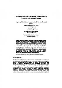
Figure 1. Generic Guardian fault hypothesis. The data at the output interface of the guardian are based on the output received from the supervised interface. Other components of the system take data from the interface of the guardian rather than from the genuine interface of the fault containment region. Consequently, it is important to be aware that the guardian may introduce new problems if it happens to become faulty itself. A simple guardian, as the central guardian discussed in this paper, will check (at the operational level of the interface specification [9]) for the expected syntax and the timing at the interface of the unit it supervises. It is thus able to transform types of faults. At its output interface the guardian will mirror the input received from the attached unit if this input complies to some specified rules. Otherwise the guardian will exhibit a predefined behavior (that complies to the fault hypothesis). A particular implementation of a guardian, however, may only transform a subset of faults (e.g., in a TTA cluster, a guardian may guarantee that a node does not send more frequently than once a TDMA round but not that the node sends in its assigned slot only [14]).
3 The Tasks of the Guardian
3.1
The purpose of the guardian is to increase the probability that TTP/C nodes of a cluster will face only faults covered by the fault hypothesis as presented in Section 2.2. In principle, this is achieved by placing a guardian at the interface(s) of a component and let it control the appearance of the respective component at the interface and, thus, act as a failure mode converter. Consequently the failure modes of the component are – at the interface to other components – replaced by the failure modes of the guardian. Figure 1 provides a generic setup of a guardian protecting some fault containment region. Note that the guardian may be considered either a supervising unit at the output interface of a component or a protecting unit at the input interface of a component. The discussions of this paper refer to the guardian as a supervising unit at the output interface. Basically the guardian imitates the behavior of a component interface that is compliant to the
A Guardian for TTP/C
In Section 2.2.1 we have introduced the types of fault containment regions of the TTA: node computers and channels of the interconnection network interface. Each of these component types requires a particular guardian design. A channel of the interconnection network has N interfaces in a cluster comprising N nodes each interfacing to one of the nodes. A guardian to supervise a channel needs to imitate each of these interfaces and thus needs to provide 2N interfaces. To check for the compliance to the fault hypothesis of network fault types, the guardian basically has to compare the data delivered to receiving nodes to the data received from the currently sending node (respecting the transmission delay). A second channel plus a comparator would implement this guardian. At every interface to a node the guardian will then be provided with the data of the supervised channel and the data of the channel of the guardian. If the channels provide different data, the guardian assumes a channel fault and does not provide the input received from the supervised channel at its output interface. However, a guardian for the channels
1 This will happen if one of the channels fails silently and a node tries to integrate into an active cluster where no I-frame is sent for the duration of the listen timeout of the integrating node. 2 Otherwise a faulty node that sends coldstart I-frames in its TDMA slots may infect the integrating node.
4
3.2
of the interconnection network is not considered in this paper. With respect to node computers, the guardian may physically either be implemented as part of the node computer (e.g., by means of self-checking mechanisms) or external to the node computer. While in general the first approach is more cost-efficient, the second approach allows for maximum fault isolation capabilities by minimizing statistical dependency of the occurrence of faults. In particular, a central guardian allows for both cost efficiency and maximum statistical independence. The guardian for node computers will have two interfaces: one interfacing to the node computer and the other one interfacing to the interconnection network. If a (correct) guardian is compliant to the fault hypothesis (regarding the types of node faults) at its interconnection network interface despite the associated node computer being arbitrarily faulty, maximum fault isolation capabilities are achieved. To guarantee compliance to the types of node faults the guardian needs to transform failures of TTP/C communications controllers as follows:
The Central Guardian Approach
Figure 2 provides the (logical) top level architecture of a TTA cluster utilizing a star topology network. The cluster comprises four regular nodes, two dedicated nodes, and two star couplers. The regular nodes are connected to each of the replicated channels of the (star topology) interconnection network via bi-directional links. Two independent central guardians are located at the center of each communications channel, i.e., at the star coupler. The guardian of a channel controls all the (frame) traffic at the respective channel. To achieve this, the guardian needs to be provided with the TTP/C clock synchronization service and needs to have access to C-state data. A dedicated node consisting of a stand-alone TTP/C protocol controller provides these services (by providing the central guardian with a regular TTP/C protocol interface, i.e., the CNI). This controller is logically (as depicted in Figure 2) a regular TTP/C controller that does not send any frames and whose existence is thus transparent to other nodes in the cluster. Physically, the controller is located at the star coupler and is part of the guardian itself.
1. SOS failures in the line encoding of frames at the physical layer 2. SOS failures with respect to the timing of frame transmission 3. transmission of any data outside the assigned sending slot (both in synchronized cluster operation and during startup) 4. masquerading of nodes during the startup phase of the protocol Additionally, to provide fault isolation to integrating nodes:
Figure 2. Star Network Architecture
5. transmission of invalid (i.e., non-agreed) C-state data
This approach provides both cost efficiency and a low statistical dependency of node and guardian faults. Cost efficiency is a consequence of needing only two guardians irrespective of the actual number of nodes in the cluster. Because of the strict “one-at-a-time” communication pattern of TDMA-based communication and the fact that a guardian protects receivers from faulty senders, it suffices to have, for all nodes, a single common guardian that is – at a particular point in time – logically assigned to the sender of the respective slot. Write access of any other node is prohibited. The actual value of statistical dependency of node and guardian faults basically depends on the particular implementation. Influencing parameters are the type of physical connection between nodes and the star coupler, independence of power supplies, physical vicinity of the devices, and others. At the logical level nodes and guardians do not have any common mode failure modes. The central guardian is both physically – as can be
Transformation of failure modes one and two ensures that transmission faults will be consistent. Supervision of failure mode three will guarantee that node can never send anything outside their assigned sending slots. Finally, hiding its identity becomes impossible to a node if the guardian checks for cheaters. Thus, all assumptions regarding the types of faults as discussed in Section 2.2.2 are covered. We will discuss the particular problems of each of these failure modes and measures to transform them with a central guardian approach in detail in Sections 4 and 5. Any problems related to startup of a TTP/C cluster and algorithms to be applied during the startup phase are not discussed in this paper. Please refer to [13] for a comprehensive discussion of problems and measures related to protocol startup with a central guardian approach.
5
seen from Figure 2 – and logically part of the interconnection network channel it is located at. Being part of the interconnection network implies that
block nodes that cheat and allows to implement mechanisms that avoid masquerading with respect to the user data contained in N-frames or X-frames. However, this document will only discuss features needed to ensure save and (fault-hypothesis-compliant) fault-tolerant cluster operation.
• the guardian can transform failure modes only if and when they become manifest at the interconnection network interface of a node • the guardian cannot transform failure modes of the interconnection network itself
4 Fault Isolation at the Physical Line Interface
Thus, the central guardian will isolate faults of node computers at their interconnection network interface and will transform faults outside the scope of the fault hypothesis to those covered by the fault hypothesis. To achieve this, the guardian will be concerned with two abstractions of the interconnection network interface of the TTP/C protocol controller:
Fault isolation at the physical line interface will guarantee that correct nodes consistently receive any data transmission that passes a correct guardian. The following paragraphs will discuss the mechanisms to be provided by the guardian to ensure fault isolation at the physical line interface.
• Physical line interface
4.1
• Semantic interface
Transmission Window Timing
Nodes will accept frames only if their respective transmission both begins and ends within the boundaries of the transmission window of the respective slot. This transmission window is statically scheduled to start and end at the same (local) time at all nodes. However, since the nodes are synchronized to each other with a non-zero precision Π only, distinct nodes have slightly differing views (with respect to physical time) of the time intervals considered to be the transmission window. Thus, a node may start transmission of a frame that meets all correctness criterions of Section 2.1 at some nodes but violates the requirement of having to start and end within the boundaries of the TDMA slot at other nodes. This will cause correct nodes to arrive at different views concerning the correctness of the respective frame. To meet agreement and validity requirements a correct node may thus start the transmission of a frame only when it can be sure that the transmission window has started at all correct nodes. Since the sender cannot possibly know whether it is the fastest or the slowest node within the distributed system, it must operate on the basis of a worst case assumption as follows (Figure 3): if the sender happens to be the fastest node, it should start transmission only δts ≥ Π time units after it has encountered the start of the transmission window. This guarantees that even the slowest (but correct) node will detect the start of the respective transmission only after (or, in the worst case, at the same time as) it has encountered the start of the transmission window according to its local clock.
At the physical line interface the guardian needs to ensure that any frame transmission is perceived consistently at all correct receivers. By acting as a single centralized authority the guardian decides whether a frame is correct or not. The algorithms to be implemented within the guardian and the algorithms present within TTP/C communications controllers must ensure that any frame transmission indicated to be correct by a correct guardian will be accepted by a correct receiver node. In particular, it must be guaranteed that any signal leaving a correct guardian is consistently interpreted by receiving nodes. At the semantic interface the guardian takes care that the transmission of a frame cannot possibly confuse receivers and cause them to proceed along different execution paths with respect to the communications protocol. This problem arises when a faulty node sends an I-frame containing an invalid C-state and some other node uses this C-state to integrate into a cluster (either in start-up or during node re-integration). Besides the tasks arising from the fault isolation requirement there are some further facilities that may improve the value of a smart centralized guardian in a TTP/C cluster, e.g., • the ability to open some or all ports on demand at the same time • provision of a semantic interface and an abort transmission command at a host interface to allow for smart centralized transmission control
Transmission Window (Slot n) Fastest Node
The first of these features allows for time sharing of the communications medium with communications protocols other than TTP/C during synchronized protocol operation. The second allows to block the transmission of a frame based on its contents. This enables a central guardian that knows (parts of) the contents of a frame to
Transmission Window (Slot n)
≤Π
≤Π
Slowest Node Physical Time
Figure 3. Slowest Node vs. Fastest Node
6
Transmission Window (Slot n) Write Access Granted
Similarly, even if the sender is the slowest node, it still needs to complete its transmission before the fastest node may encounter the end of the transmission window. I.e., it must be assured that the transmission of the node is finished δtf ≥ Π time units before the sending node itself encounters the end of the transmission window.
Bus Guardian Transmission Window (Slot n) Fast Node Transmission Window (Slot n)
≤Π ≤Π Actual Transmission
Transmission Window (Slot n)
≤Π ≤Π
Slow Node Physical Time
Fastest Node Transmission Window (Slot n)
≤Π ≤Π Actual Transmission
≤Π ≤Π
Figure 5. Guardian Relative to Fast and Slow Node
Slowest Node Physical Time
Figure 4. Actual Transmission of Slowest and Fastest Node
time units after the start of the (guardian-local) transmission window and ending δgf ≥ Π time units before the end of the (guardian-local) transmission window, any granted transmission will take place at times where all correct nodes have their respective transmission windows opened; it does not matter whether the guardian is the fastest or the slowest node within the cluster. However, Figure 5 also shows that a correct node that is to transmit in a particular slot needs to wait δts ≥ Π + δgs ≥ 2Π (i.e., longer than in a cluster without a central guardian) time units after the start of the transmission window before it may start transmission. If the respective sender is the fastest node within the cluster and the guardian happens to be the slowest node, then write access to the communications medium will only be granted Π + δgs ≥ 2Π time units after the sender has encountered the start of the transmission window. Further, in a scenario where the guardian is the fastest node and the sender is the slowest node, transmission still needs to be completed by the time the guardian stops granting write access. Consequently, transmission must be finished δtf ≥ Π + δgf ≥ 2Π time units before the transmission window ends. From all this it follows, that the transmission window needs to be at least δts +δtf ≥ 4Π time units longer than a node may need to transmit the respective data frame. By the time of this writing, Rushby provides formal verification of the arguments of this paragraph in [12].
Summarizing, we can say that a sender must wait δts ≥ Π time units before it starts to transmit a frame and that the transmission window must be long enough to allow any node to finish frame transmission δtf ≥ Π time units before it encounters the end of the transmission window. Consequently, the transmission window needs to be δts + δtf ≥ 2Π time units longer than it takes a node to transmit its frame (Figure 4). The time it takes a node to transmit its data must be evaluated for the slowest sender that may exist in a cluster. Further, this time needs to comprise any transmission delays not compensated for by other measures (e.g., hardware-implemented transmission delay compensation). The rules scheduled above will guarantee both agreement and validity if the sender is correct. However, a sender that suffers a fault in the time domain may still transmit a frame that confuses correct receivers. This inconsistency scenario can be solved by a central guardian. To achieve this, the guardian must ensure that even a faulty node cannot possibly send at a time some correct nodes have their transmission window opened while others have not. Consequently, it will begin to grant write access to the communications medium only δgs ≥ Π time units after it has encountered the start of the transmission window at its local copy of the global time. It will stop granting write access δgf ≥ Π time units before the transmission window ends. Figure 5 shows the guardian timing for two distinct scenarios (the time window where the guardian grants write access to the interconnection network channel is called access window): first, the guardian is assumed to be the slowest node of the cluster. In this case, the timing relative to the fastest node is of relevance. Second, if the guardian is the fastest node of the cluster, the timing relative to the slowest node will have to be considered3 . Figure 5 shows that if the guardian grants write access to the communications medium starting δgs ≥ Π
4.2
Transmission Window vs. TDMA Scheme
Figure 6 shows three slots aligned in a TDMA scheme for a configuration where the guardian is the slowest node of the cluster (the actual transmission is shown for the fastest and the slowest non-faulty node). This section discusses the minimal distance ∆ between the access windows of two successive slots. Obviously, a lower bound for ∆ is zero: if ∆ were smaller than zero, two nodes would be allowed to access the shared communications medium concurrently, which may corrupt the transmissions of both. If ∆ is greater than or equal to zero, then the guardian will protect the transmission of non-faulty nodes against a babbling idiot [14]. On the other hand, a save choice for ∆ is any value
3 Note, that the “Fast Node” and the “Slow Node” of Figure 5 cannot exist in a single cluster and be both correct. Rather, Figure 5 shows the timing of the guardian relatively to the fastest node if the guardian is the slowest node of the cluster and vice versa.
7
physical line returns to some idle value when the guardian closes the access window. This may cause a signal edge that satisfies the timing requirements of some set of receivers while violating the requirements of some other set of receivers. To prevent this the guardian makes use of the fact that a correct transmission (provided the guardian is correct) will start within a time window of ±Π (i.e., the startwindow) around the scheduled start according to the local clock of the guardian. If the transmission has not started when the startwindow ends, the guardian will close the write access window for the remainder of the respective slot. Since the number of bits to be transmitted and, thus, the maximum amount of time needed to complete a correct transmission (with respect to the timing of the line encoding algorithm) is known a priori, the write access window can be chosen in a way that a cut-off fault can only occur if preceded by a coding rule violation. However, a correct guardian will detect a coding rule violation (cf. Section 4.4) and consistently signal the fault to all attached receivers.
Figure 6. TDMA Scheme greater than or equal to δgs + δgf (Figure 7. In this case, two transmission windows would locally (i.e., at a node) never overlap and a slot would need to be δts + δtf ≥ 4Π time units longer than needed to transmit the respective frame. In this case the correctness argument follows from the correctness argument of the transmission window timing [12]: the guardian allows frame transmission only at times when all correct receivers have their respective transmission windows opened and all correct nodes reside in the same transmission window. δ gf δ gs
∆ ≥ 2Π
4.4
Figure 7. TDMA Scheme
Similar to cut-off SOS faults, coding SOS faults may be caused by transitions of the signal at the physical line, which satisfy the timing requirements of some set of receivers but violate the requirements of some other set. However, coding SOS faults may also originate from deficient signal levels. Finally, spikes, which may be interpreted either as invalid signal values or invalid transition timing, may be the source of coding SOS faults. Basically, a strategy similar to the one chosen when assuring consistency with respect to the transmission window (Section 4.1) can solve the problem. The guardian needs to know the tolerance granted to a correct transmitter. It checks any granted transmission and invalidates it by aborting the transmission if the transmitter violates the coding rules. Similarly, receivers need to know the tolerance thresholds of the guardian (plus the physical characteristics of a correct transmission line) and must accept any transmission that a correct guardian allows to pass. It is straight forward to transform the results of Section 4.1 to this fault scenario in the value domain.
Whether ∆ may be smaller than δgs + δgf depends on the particular implementation of TTP/C controller hardware. In this case, nominal transmission windows will overlap. However, a correct guardian guarantees that there is a gap of at least ∆ time units between any two transmissions assigned to distinct slots. If a communications controller is able to identify an idle time of ∆ time units on the communications medium as the end of the current transmission window, it will always assign activity on a channel to the node the central guardian is currently granting write access to. With the current TTP/C controller chip hardware, this minimum time for ∆ is at least three bit cells [11]. However, for the time being the execution time required by the TTP/C protocol between two successive transmissions is considerably larger than this.
4.3
Avoiding Coding SOS Faults
Avoiding “Cut-Off” SOS Faults Transmission Window (Slot n) Write Access Granted
Transmitter Signal with Spike Bus Guardian Sampling Points Receiver A Sampling Points Receiver B Sampling Points
Bus Guardian ...
SOS-faulty Sender
...
Signal at Receivers
Spike
Physical Time
Figure 9. Transmission Signal with a Spike
Figure 8. Cut-Off SOS Fault
However, depending on the particular implementation of the decoding of the physical line signal particular care must be taken with purely passive approaches. As can be seen from Figure 9, any spike that has a duration below the sampling period of the guardian and that proceeds to
Figure 8 illustrates the cut-off SOS fault problem: a SOS faulty sender transmits an otherwise correct frame close to the closing end of the time window the guardian grants write access; the transmission lasts slightly longer than write access is granted. Further, we assume that the 8
receivers may be considered a SOS fault. Consequently, receivers either need to be tolerant to spikes or some active measures at the guardian must be taken to avoid coding rule SOS faults (e.g., low-pass filter). Still, the guardian will have to face the problem of late faults (i.e., faults in frame transmission that become manifest only in the last signal transition on the physical line), which will require some additional active measure at the guardian to signal this condition to receiving nodes. Further, this signaling of late faults needs to be interpreted by the receivers. Since the actual TTP/C communications controller hardware is not tolerant to noise on interconnection network channels nor provides means to interpret signals indicating late faults, a guardian for this hardware needs to perform active signal reshaping. Thus, the guardian decodes the incoming physical line signal and encodes it again. The advantage of this approach is that receivers and guardian may be designed according to the same tolerance level and that the existence of the guardian remains transparent to the nodes. Whatever signal the (correct) guardian is able to decode will be encoded at the incoming link of the guardian to become a well-shaped and well-timed signal at the outgoing links of the guardian again. In particular, any spikes not detected by the decoder will disappear. In addition, the decoder unit of the guardian may be smarter (i.e., implement more sophisticated signal restoration algorithms) than an ordinary node can be due to cost constraints. Another advantage of active reshaping is that it relieves the guardian from the tricky task of signaling faults in the last signal transition. Since the encoder of a correct guardian will create a valid physical signal, all receivers will detect a correct physical signal. Any problems arising from late faults will be transformed either to a correct frame, to a frame that happens to be too short, or will result in the CRC calculation to fail. Note, however, that active reshaping requires the central guardian to maintain a buffer for decoupling the incoming data stream (originating at the actual sender) from the outgoing data stream (originating at the central guardian). The minimum transmission delay introduced by active reshaping (given in number of bits) is determined by the line encoding rules (δle ), the difference in clock speed between sending node and central guardian ρ, and the maximal number of bits in a frame b:
actual sender is the fastest node, the guardian needs to have a buffer comprising at least δle + 4 · ρmax · bmax bits.
5 Fault Isolation at the Semantic Interface As stated in Section 3.1, fault isolation at the semantic interface needs to ensure that the contents of (faulty) frames cannot possibly cause failures at a correct receiver. In particular, it must be guaranteed that - regardless of the contents of a frame - all correct receivers will proceed along corresponding execution paths of the communications protocol. To identify the algorithms necessary to ensure fault isolation at the semantic interface it is inevitable to be aware of the parameters that influence the flow of control of the TTP/C communications protocol. If some algorithms - either of the guardian or the communications protocol itself - can ensure consistency of all these parameters at all correct nodes, the fault isolation requirement is satisfied. In the TTP/C protocol there are four parameters, which determine the execution path of the protocol at a node during synchronized operation: 1. locally stored TTP/C configuration and control data (called MEDL) 2. host computer system 3. progression of global time 4. correctness of incoming data frames Further, a fifth parameter needs to be considered during protocol start-up or node integration: 5. the C-state communicated in I-frames or X-frames, respectively From the above, parameter one does not require any fault isolation mechanisms at the interconnection network level: this is a fully local parameter, which is correct at a correct node. An incorrect node has no means of changing the contents of the MEDL (which is contained in readonly memory) of a remote node. As for the second parameter, we assume that the host computer system will implement a fault-tolerance layer, which enables the host computer to base its decisions on some fault-tolerant data rather than on the information received from a single node. Thus, fault isolation at the host computer is achieved by fault tolerance mechanisms (which are straight forward to implement provided fault isolation at the communications system level can be ensured [3, 5]). Parameter three, progress of global time, has two aspects. First, global time is derived from the progression of local time at a node. This aspect does not need fault isolation provided by the guardian, as every node is equipped with its own private oscillator. Second, global time is – at
δmin = δle + 2 · ρmax · bmax . The sending node needs to be always at least δle bits ahead of the central guardian to allow for performing line encoding at the guardian. To guarantee the lead of δle bits throughout the whole frame transmission (despite the sender maintaining the slowest clock and the central guardian maintaining the fastest clock), the guardian needs to buffer another 2 · ρmax · b bits before starting to forward the frame. However, if the guardian is the slowest node and the 9
transmits a frame, which node B – because of some local incoming link fault – does not receive correctly. Node B (according to the self-confidence principle of TTP/C) assumes node A to have suffered a transmission fault and removes A from its membership. The next sending slot be the one of B and B transmits an I-frame that does not acknowledge the transmission of A. Thus, A waits for a second node to either acknowledge its initial transmission or the view of node B, i.e., that frame transmission has failed. Since C, which has not received the transmission of A because it was not active then, basically broadcasts the view of node B in the subsequent slot. Consequently, A concludes that its transmission was faulty and – depending on the actual TTP/C configuration – will shut down although its transmission was in fact correct. B will shut down because it suffered an incoming link failure. C will shut down because it copied the faulty view of B. Thus, the local fault of node B has propagated to two correct nodes.
distinct points in the execution path of the TTP/C protocol – influenced by a clock synchronization algorithm. In TTP/C this clock synchronization algorithm is inherently fault tolerant and provides fault isolation as long as there exists at most one faulty clock in a cluster. Further, clock synchronization is performed at least once every TDMA round. Thus, as a consequence of the requirement that at most one TTA node becomes faulty every TDMA round (cf. Section 2.2.2), the algorithm that establishes a distributed global time base provides fault isolation by itself. To ensure consistency with respect to correctness of frames, a correct guardian needs to guarantee that the correctness criterion specified in Section 2.1 provides the same results at all correct receivers. Thus, as discussed in Section 4, a correct guardian will allow write access of some node only during its specified time slot. Further, if the current sender creates a correct physical signal on the communications channel, the channel will deliver the same correct physical signal to all receiver nodes. If the current sender does not provide a physically correct signal, a correct channel will deliver either an incorrect signal to all nodes or no signal at all. Consistency of the results of the CRC checks trivially follows from consistency of the received physical signal. Similarly, if any two correct nodes receive a syntactically correct frame, it will contain identical data. The remaining parameter, namely the contents of Iframes, will be discussed in the remainder of this section. As stated above, the contents of I-frames are of particular interest for nodes that like to (re-) integrate into an operative cluster and in the course of protocol start-up.
5.1
correct node ...
faulty node
A
B
infected node C
...
Physical Time C has started and waits for I-frame
C has received B's I-frame and uses it for integration
Figure 10. Fault Propagation at Semantic Interface
To isolate this kind of fault the guardian must perform semantic analysis of the contents of frames and ensure that
Re-Integration
• only frames intended to be I-frames (or X-frames) carry the respective identifier bit in their frame header
A node that is prepared to integrate into a cluster waits to receive an I-frame. This I-frame will contain the C-state of the sender where the C-state comprises the sender’s view of the current state of configuration of the distributed system. In particular, it contains a membership list indicating the nodes that are considered to operate correctly, the global time at the start of transmission of the I-frame message, and the current position within the MEDL, i.e., the current TDMA slot within the global message schedule and the current mode of communications. If an integrating node simply copies the contents of the I-frame it receives first upon integration and the respective sender happens to be faulty, then the integrating node will become an accomplice of the faulty node and will maintain an invalid C-state also. In general, this will cause the integrating node, which is correct, to be infected by a fault of some other node and to lose its membership and shut down during the following TDMA round (in a single fault scenario, cf. [4]). However, in a worst case scenario the fault of some node may even propagate to two other nodes. Consider a scenario as depicted in Figure 10: Node A correctly
• I-frames (and X-frames) carry a valid C-state. Otherwise, i.e., when receiving an I-frame (or X-frame) carrying an invalid C-state or a frame that is – according to the MEDL – supposed to be an N-frame but carries the I-frame identifier bit, the central guardian will invalidate the respective frame by aborting the transmission. This, however, is a relatively sophisticated service since – in opposition to fault isolation at the physical line interface – it cannot be accomplished by the provision of pre-planned actions. Rather, it implies that the guardian compares the C-state information contained in a TTP/C frame with its local C-state and invalidates the respective frame (e.g., by aborting the transmission at some time the guardian can be sure that all correct receivers consistently perceive the abortion). Since aborting broadcasts is – besides store-and-forward – the sole mechanism that allows the guardian to signal transmission faults to receivers while the existence of the guardian remains transparent to the receiving nodes, it is the mechanism chosen
10
in the presented approach. However, abortion needs to be accomplished in real-time and, thus, the execution speed of the guardian will limit the bandwidth at the medium it supervises.
5.2
as shadowing is transparent at this level of communications) and the transient fault will be transformed into a permanent fault. Consequently, if the guardian finds that two members of a set of shadows acquire the respective shared sending slot it cannot – at the protocol level – find out which one of them is faulty. This is only possible if the bus guardian is active before the first shadow node acquires the sending slot (the protocol implements deterministic behavior with respect to the assignment of an unused slot to the nodes of a set of shadows).
Support for Multiplexed Nodes
Nodes that require small bandwidth and low update frequencies compared to the TDMA round frequency may share a TDMA slot. Still, only one node will be allowed to send frames in a particular slot and will be assigned write permission every n TDMA rounds. Preplanned configuration stored in the message descriptor list (MEDL) ensures that slots are always assigned exclusively to a single node. Nodes that share a TDMA slot are called multiplexed nodes in TTP/C. Currently, we do not see any need for dedicated services to support multiplexed nodes. Basically, there is no particular difference between multiplexed nodes and regular nodes with respect to the algorithms of the guardian. The fact that multiplexed nodes require broadcast slots less frequently than regular TTP/C nodes will be reflected in guardian configuration data derived from the MEDL.
5.3
6 Revised Fault Hypothesis The presented interconnection network channels containing a central guardian still need to be compliant to the fault hypothesis of Section 2.2.3. Further, a correct channel including a central guardian must still provide the service of a correct interconnection network channel as stated in Section 2.2.1. Additionally, a correct channel comprises a correct guardian. In a single fault scenario (cf. Section 2.2.4) a TTA cluster with interconnection network channels comprising a central guardian can withstand an arbitrary faulty node. At the logical level no fault will propagate to correct nodes. If either of the channels fails there will still be a correct path for exchanging frames between nodes. Further, the central guardian guarantees that integrating nodes will never be infected by incorrect nodes. To allow for arbitrary node faults at the physical level also, the physical links between a guardian and the nodes and the two guardians must ensure that physical damage (e.g., short circuit) at a particular unit cannot proceed to another unit. Note, that the guardian does not check for a minimum configuration (Section 2.2.4). Checking for a minimum configuration can be performed at the application layer. If the minimum configuration requirement is correctly handled at the application layer, the worst case is the whole cluster shutting down. However, all that a guardian can do when detecting a violation of the minimum configuration requirement is to shut down the cluster also.
Support for Shadow Nodes
The shadow node facility of TTP/C provides hotstand-by redundancy that is an abstraction to the host computers of the set of shadows and transparent to all other nodes of the cluster. I.e., the protocol does not provide any means to allow a receiver to find out which node of a set of shadows is the active member at some point in time4 . In particular, this applies to the TTP/C controller being part of the central guardian. Thus, if a guardian has to integrate into an active TTP/C system, the guardian has no means to learn about the active node of some set of shadows except for sensing the stubs to all shadows of the set in the respective TDMA slot. If the guardian finds that only one of the set of shadows is sending in the slot, it can – assuming that there is only a single faulty node in a cluster – safely assume that this is the currently active shadow. However, sensing will not work if the set of shadows contains a faulty node that sends in the shared slot in addition to the currently active node. The guardian protecting the other channel will forward only messages from the correct shadow. Thus, nodes in the cluster will receive correct messages in the respective slot. Since receiving nodes will acknowledge the reception, a passive shadow node that happened to suffer some transient fault that caused it to send in its shared slot will find that “its” messages are acknowledged (since the acknowledgement at the protocol level cannot possibly include a shadow ID
7 Conclusion In this paper we have presented a central guardian approach to enforce fault isolation in the Time-Triggered Architecture despite arbitrary node failures. To achieve these fault isolation capabilities every node needs to be supervised by two guardians being assigned to mutually distinct fault containment regions. The strict “one-at-atime” communication pattern of TDMA-based communication as utilized by TTP/C allows to implement these guardians as part of the interconnection network. This implementation needs only two guardians for the whole cluster rather than two guardians for every node while
4 Of course, the application system may broadcast a shadow ID with its messages. However, this ID is application data and not checked by the communications protocol. Thus, the protocol does not prevent that some active shadow cheats with respect to its shadow ID.
11
still providing the same fault isolation capabilities as local guardians, thus allowing for a cost-efficient solution.
Institut f¨ur Technische Informatik, Treitlstr. 1-3/182-1, 1040 Vienna, Austria, 2002. [14] C. Temple. Avoiding the Babbling-Idiot Failure in a Time-Triggered Communication System. In Proceedings of the 28th Annual International Symposium on FaultTolerant Computing (FTCS-28), pages 218–227, June 1998.
References [1] A. Ademaj. Slightly-Off-Specification Failures in the TTA Bus Topology. Research Report 40/2001, Technische Universit¨at Wien, Institut f¨ur Technische Informatik, Treitlstr. 1-3/182-1, 1040 Vienna, Austria, 2001. [2] G. Bauer, H. Kopetz, and P. Puschner. Assumption Coverage under Different Failure Modes in the TimeTriggered Architecture. 8th IEEE International Conference on Emerging Technologies and Factory Automation (ETFA 2001), Antibes Juan-les-pins, France, pages 333– 341, Oct. 2001. [3] G. Bauer and H. Kopetz. Transparent Redundancy in the Time-Triggered Architecture. In Proceedings of the International Conference on Dependable Systems and Networks (DSN 2000), pages 5–13, New York, USA, June 2000. [4] G. Bauer and M. Paulitsch. An Investigation of Membership and Clique Avoidance in TTP/C. In Proceedings 19th IEEE Symposium on Reliable Distributed Systems (SRDS’00), pages 118–124, N¨urnberg, Germany, Oct. 2000. [5] G. Bauer. Transparent Fault Tolerance in a TimeTriggered Architecture. PhD Thesis, Technische Universit¨at Wien, Institut f¨ur Technische Informatik. [6] C. Jones, M.-O. Killijian, H. Kopetz, E. Marsden, N. Moffat, M. Paulitsch, D. Powell, B. Randell, A. Romanovsky, and R. Stroud. Revised Version of DSoS Conceptual Model. Project Deliverable for DSoS (Dependable Systems of Systems), Research Report 35/2001, Technische Universit¨at Wien, Institut f¨ur Technische Informatik, Treitlstr. 1-3/182-1, 1040 Vienna, Austria, 2001. [7] H. Kopetz, G. Bauer, and S. Poledna. Tolerating Arbitrary Node Failures in the Time-Triggered Architecture. SAE 2001 World Congress, March 2001, Detroit, MI, USA, Mar. 2001. [8] H. Kopetz. TTP/C Protocol – Version 0.5. TTTech Computertechnik AG, Sch¨onbrunner Straße 7, A-1040 Vienna, July 1999. Available at http://www.ttpforum.org. [9] H. Kopetz. On the Specification of Linking Interfaces in Distributed Real-Time Systems. Unpublished draft, Technische Universit¨at Wien, Institut f¨ur Technische Informatik, Treitlstr. 1-3/182-1, 1040 Vienna, Austria, 2002. [10] L. Lamport, R. Shostak, and M. Pease. The Byzantine Generals Problem. ACM Transactions on Programming Languages and Systems, 4(3):382–401, July 1982. [11] D. Maurer, J. Vilanek, M. Sprachmann, and O. Maischberger. Communication Controller Functional Design, Version 1.1.1. Technical report, Technische Universit¨at Wien, Institut f¨ur Technische Informatik, Treitlstr. 13/182-2, 1040 Vienna, Austria, 1998. [12] J. Rushby. Formal Verification of Transmission Window Timing for the Time-Triggered Architecture. Technical Report Deliverable 24b, SRI Project 11003, Computer Science Labaratory, SRI International, Menlo Park CA 94025, Mar. 2001. [13] W. Steiner, G. Bauer, and H. Kopetz. Using a Central Guardian for a Fault-Tolerant System Startup of TTP/C. Research Report 16/2002, Technische Universit¨at Wien,
12