May 9, 2007 - Available on CMS information server. CMS CR 2007/017 .... CMS stores all calibration information in a dedicated database system, available to ...
CMS CR 2007/017
Available on CMS information server
CMS Conference Report 9 May 2007
The CMS High Level Trigger System A. Afaq8) , W. Badgett8) , G. Bauer9) , K. Biery8) , V. Boyer5) , J. Branson6) , A. Brett5) , E. Cano5) , A. Carboni5) , H. Cheung8) , M. Ciganek5) , S. Cittolin5) , W. Dagenhart8) , S. Erhan5)7) , D. Gigi5) , F. Glege5) , R. Gomez-Reino5) , M. Gulmini2)5) , J. Gutleber5) , C. Jacobs5) , J. C. Kim4) , M. Klute9) , J. Kowalkowski8) , E. Lipeles6) , J. A. Lopez Perez5) , G. Maron2) , F. Meijers5) , E. Meschi5) , R. Moser1)5) , E. Gutierrez Mlot5) , S. Murray8) , A. Oh5) , L. Orsini5) , C. Paus9) , A. Petrucci2) , M. Pieri6) , L. Pollet5) , A. Racz5) , H. Sakulin5) , M. Sani6) , P. Schieferdecker5) , C. Schwick5) , E. Sexton-Kennedy8) , K. Sumorok9) , I. Suzuki8) , D. Tsirigkas5) , J. Varela3)5)
Abstract The CMS Data Acquisition (DAQ) System relies on a purely software driven High Level Trigger (HLT) to reduce the full Level-1 accept rate of 100 kHz to approximately 100 Hz for archiving and later offline analysis. The HLT operates on the full information of events assembled by an event builder collecting detector data from the CMS front-end systems. The HLT software consists of a sequence of reconstruction and filtering modules executed on a farm of O(1000) CPUs built from commodity hardware. This paper presents the architecture of the CMS HLT, which integrates the CMS reconstruction framework in the online environment. The mechanisms to configure, control, and monitor the Filter Farm and the procedures to validate the filtering code within the DAQ environment are described.
Presented at IEEE Realtime, Fermilab, May 4, 2007 1)
Vienna University of Technology, Vienna, Austria
2)
INFN - Laboratori Nazionali di Legnaro, Legnaro, Italy
3)
LIP, Lisbon, Portugal
4)
Kyungpook National University, Daegu, Kyungpook, South Korea
5)
CERN, Geneva, Switzerland
6)
University of California San Diego, La Jolla, California, USA
7)
University of California, Los Angeles, California, USA
8)
FNAL, Batavia, Illinois, USA
9)
Massachusetts Institute of Technology, Cambridge, Massachusetts, USA
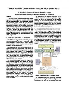
Figure 1: CMS DAQ Architecture. The size of the event builder (72 Readout Units, 288 Builder Units) represents one “slice”; the system can be equipped with up to eight slices.
1
Introduction
The Large Hadron Collider (LHC) at CERN is scheduled to begin operation in 2007 and will deliver proton-proton collisions to the CMS[1] detector at a rate of 40 MHz. This rate must be significantly reduced to comply with the performance limitations of the mass storage hardware, and the capabilities of the offline computing resources to process the collected data in a timely fashion for physics analysis. At the same time, the physics signals of interest must be retained with high efficiency. CMS features a two-level trigger system to reduce the rate to approximately 100 Hz. The Level-1 trigger[2] is based on custom hardware and designed to reduce the rate to about 100 kHz, corresponding to 100 GB/s, assuming an average event size of 1 MB. The HLT[3] is purely software-based and must achieve the remaining rate reduction by executing sophisticated offline-quality algorithms. No additional intermediate trigger level is required, as the event builder is dimensioned such that complete events are assembled at the full Level-1 accept rate. HLT algorithm sequences are moreover efficiently scheduled: in each sequence (or “path”) algorithms are executed in order of increasing complexity, and execution of a path is stopped unless evidence for the signal of interest is found. This way more sophisticated and time consuming reconstruction algorithms are only seldom applied. The CMS Trigger system must decide the fate of each event within a very short time, a true “needle-in-the-haystick” task and the foundation for our quest for new physics phenomena. A flexible and accurate HLT selection together with the stable operation of the DAQ are vital for the success of the CMS physics program. The architecture of the CMS HLT, which combines the power of the offline reconstruction[4] with the robustness required for reliable online operation of the DAQ, is presented in the following.
2
Architecture
The global architecture of the CMS DAQ system is sketched in Fig. 1. Event fragments are read out and stored in “readout buffers” (Readout Unit , RU) for each event accepted by the Level-1 trigger. The fragments are subsequently assembled into complete events by an Event Builder through a complex of switched networks into “event buffers” (Builder Unit, BU). The full event content is then handed to one of the HLT Filter Units (FU) for processing, and events found to be sufficiently interesting for offline analysis are forwarded to the StorageManager (SM). All DAQ components are based on a common framework (XDAQ[5]) for distributed operation, which provides all DAQ components with coherent access to basic services to interoperate, exchange data, publish monitoring information, and receive external messages. Components are configured and controlled by the CMS Run Control and Monitoring System (RCMS[3]), predefining a hierarchical control structure for all the detector subsystems involved in the DAQ. RCMS distributes commands, and monitors the state of all system components. 2
Figure 2: Filter Unit architecture: the responsibilities to receive, reformat, and send accepted events (ResourceBroker), and to reconstruct the physics content (EventProcessor) are split. A Filter Unit must receive and reformat events from the event builder, execute a series of physics reconstruction and filter algorithms, and forward accepted events to the StorageManager. The internal architecture of each Filter Unit is illustrated in Fig. 2. It consists of two separate applications, the ResourceBroker, which exchanges data with the DAQ, and the EventProcessor, which integrates the reconstruction software. The physics algorithms are extensively tested on simulated data, and every effort is made to anticipate and appropriately handle events with unusual content. It is unavoidable though that some scenarios will be encountered in real detector data for the first time, potentially leading to unexpected algorithm behavior or even abnormal termination. The decoupling of physics algorithm execution from data flow allows each Filter Unit to continue operation, recover the content of the problematic event, and forward it to be stored unprocessed. Reconstruction and detector experts can access and analyze the data offline to understand and eliminate the problem. The robustness of the DAQ and the ability to study problem-events offline are crucial for the commissioning of the detector and the HLT. The three Filter Farm components are described in more detail in the following sections.
2.1
ResourceBroker
Given the involved event sizes and rates, reformatting raw events consisting of a large number of small data fragments into the physical memory of a Filter Unit requires high bandwidth I/O, while the subsequent HLT processing is mostly CPU intensive. The ResourceBroker is responsible for receiving and reformatting raw events from the Builder Unit, and dispatching processed and accepted events to the StorageManager via the communication protocol based on the proposed I2O[5] standard. The ResourceBroker is a pure DAQ component, unaware of the HLT processing code. Since each Filter Unit hosts several CPU cores and thus several filtering processes are executed in parallel, the ResourceBroker manages a queue of reformatted events in a shared memory buffer. Filtering tasks running as separate processes on the same machine are granted read-only access to the buffer and consume available events on demand. The ResourceBroker manages a separate shared memory buffer for events accepted by any of the filtering processes, and reintegrates them with the global data stream. Write-access to each shared memory segment is given to only one filter process at a time, ensuring system-level protection against data corruption between processes. Abnormally terminated filter processes are automatically detected and the corresponding raw data is recovered and forwarded to be stored unprocessed for later offline error analysis.
2.2
EventProcessor
The EventProcessor encapsulates the event processing machinery of the CMS reconstruction, providing the full flexibility required to execute complex physics algorithms. Only the components within the filter job responsible to read raw event data and to output processed selected events have access to the shared memory buffer (Sec. 2.1) interacting with the DAQ. The loose coupling of the filter processes to the rest of the DAQ via asynchronous shared memory communication provides the high degree of robustness and fault tolerance described above. Experience 3
shows furthermore that algorithms are typically developed and optimized offline, by analyzing simulated or already recorded data samples. Sharing the same software infrastructure allows for the fast and efficient migration of improved reconstruction and filtering strategies from offline studies to HLT operation. It moreover spares algorithm developers the cumbersome task of providing the same or similar functionality within different software contexts.
2.3
StorageManager
All Filter Units send events accepted by the HLT to the StorageManager. Events are received and organized in streams according to the parameters of the current run and the specific physics content of each individual event as identified by the filter decision. Events are subsequently written to disk files. Each StorageManager transaction is only acknowledged to the ResourceBroker when complete, thus providing an indirect back-pressure mechanism in case of large fluctuations of the accept rate. Each Filter Unit is paced by balanced counts of sent and acknowledged events. Besides collecting event data, the StorageManager is also responsible for collecting Data Quality Monitoring (DQM) information (see Sec. 6).
3
Control
When Run Control initializes the DAQ system, each application process is started on its assigned computing node. All Filter Farm applications implement a common State Machine, which is defined by the three states Halted (initial state), Configured, Enabled, and transitions between these states. Run Control can be instructed to send control messages to each application and trigger state transitions, associated with a set of actions and an expected target state. The state of each application is monitored at all times. Controlled components actively notify modifications of their state, which are accounted for. Unexpected or missing notifications are handled appropriately.
4
Configuration
The creation of an HLT configuration and its deployment to all Filter Farm nodes is based on a robust database design. The definition of a configuration, consisting of sequences of reconstruction and filtering algorithms, is abstracted in a relational database schema. For a given software release, a thin code parsing layer is employed to discover all available components and store them as templates in the database. Specific configurations based on these templates are created and stored with a dedicated graphical tool. Configurations can be retrieved and transformed into several useful representations, most notably the one used by the reconstruction framework to configure, to be distributed to each filter node via the Run Control layer. Formatting and deploying of the configuration are decoupled from the database schema, allowing the target configuration grammar to evolve independently. The creation and manipulation of configurations stored in the database is kept flexible enough for fast and efficient development, and is designed to offer data integrity and consistency over the full lifetime of the experiment.
5
Calibration
To reach its full potential, each HLT process needs access to the full set of sub-detector calibrations, which is expected to amount to approximately 100 MB of data for the fully equipped detector per process. The calibration is conceptually separated from the configuration. CMS stores all calibration information in a dedicated database system, available to the local DAQ and offline reconstruction centers around the world, with generic access mechanisms from within the software framework. The infrastructure for O(1000) processes to access this sizable amount of data at the same time is provided by means of a local calibration cache on each node, which services HLT algorithm requests without explicit database transactions. This cache can be updated asynchronously such that the performance of the global DAQ is not impacted by extensive concurrent access to the database. The data management mechanisms guarantee that for each recorded event, the calibration applied during data-taking can be traced offline.
6
Monitoring
The monitoring of the Filter Farm complex consists of two tasks: monitoring the applications, and monitoring the quality of the detector data and and their physics content. The DAQ software framework provides each application with standardized mechanisms to publish information about its current state and performance. This information is collected, optionally stored in a database, and dispatched to monitor applications which process and visualize 4
Figure 3: Playback Setup of the Filter Farm: events are read by a dedicated event builder replacement from a file and injected into the Filter Units using the standard data exchange protocol. the state and performance of the whole system and each of its components. For the Filter Farm, the state of each application, the throughput and CPU performance on each node, and the output bandwidth to mass storage represent crucial monitoring informations to be at the finger tips of the system operators at all time. To ensure that the recorded event data is meaningful and meets the expectations in terms of physics, the quality of the stored events must be monitored. A DQM infrastructure[7] provides the tools to create, serialize, and collect accumulated statistical information about data quality. Automated client processes compare current distributions to references and detect deviations. Operators are informed about potential inconsistencies, and experts can use DQM tools to investigate the causes of the problem. A small fraction of the bandwidth to mass storage is reserved to transport DQM information, which is accumulated within each EventProcessor, to the StorageManager between predefined intervals. The StorageManager collects this information and dispatches it to a dedicated server, where it is preprocessed and collated, and accessible to the clients. The dedicated DQM path ensures that the number and frequency of DQM requests does not impact the performance of the StorageManager during data-taking.
7
Validation
To validate the stable operation of the Filter Farm infrastructure and the functioning and physics performance of any given HLT configuration, a Playback system is setup using a small number of nodes. A special Builder Unit (“AutoBU”) mimics the CMS detector readout and event building, reading recorded or simulated physics events from files and reformatting the raw portion of each event according to the standard protocol of the event builder. The configuration of the Playback system is illustrated in Fig. 3, where an EventProcessor is used to read event data stored in the common offline file format. A dedicated HLT validation system will be put in place throughout the lifetime of the experiment to validate the performance and quality of new HLT configurations before deployment.
8
Conclusion
The CMS Filter Farm is integrated with the DAQ through a common framework and controlled, configured, and monitored through standardized and reliable mechanisms established for the entire DAQ system. The internal architecture of each Filter Unit decouples the DAQ from the physics-algorithms and provides the full-fledged offline reconstruction to process and filter detector events. Problematic events are handled without impacting the operation of the global DAQ and recovered and stored for offline expert inspection.
Acknowledgment We acknowledge support from the DOE and NSF (USA), KRF (Korea) and Marie Curie Program.
5
References [1] The CMS Collaboration, CMS Technical Proposal, CERN LHCC 94-38, 1994. [2] The CMS Collaboration, CMS, The TriDAS Project, Technical Design Report, Volume 1: The Trigger Systems, CERN LHCC 2000-38, 2000. [3] The CMS Collaboration, CMS, The TriDAS Project, Technical Design Report, Volume 2: Data Acquisition and High-Level Trigger, CERN LHCC 2002-36, 2002. [4] C. D. Jones et al., “The new CMS data model and framework”, CHEP’06 Conference Proceedings, 2007. [5] J. Gutleber and L. Orsini, “Software architecture for processing clusters based on I2O”, Cluster Computing 5(1):55-64, 2002. [6] C. D. Jones, “Acess to non-event data for CMS”, CHEP’06 Conference Proceedings, 2007. [7] C. Leonidopoulos et al., “Physics and data quality monitoring at CMS”, CHEP’06 Conference Proceedings, 2007.
6