The complexity of formulating design(ing) grammars Rudi Stouffs1 , Dan Hou2 1 National University of Singapore / Delft University of Technology 2 National University of Singapore / Tianjin University 1
[email protected] 2
[email protected] We are concerned with the complexity of formulating rules within a design grammar, i.e., a grammar for designing. Our motivation comes from an active development of a design grammar using railway station design as a demonstration study. In this paper, we identify a number of difficulties that may arise when developing shape rules and present approaches for graphical rule specification that can serve to overcome these difficulties. Specifically, we present examples where drawing shape rules and augmenting these with control conditions or rule constraints offer insufficient support for the rules' intricacies, and propose conventions for drawing and specification that support the explication of these exemplar shape rules, aiming not to overly complicate the drawing and specification process. We borrow from other authors where appropriate, and do not concern ourselves with implementation issues, at this point. Keywords: Design grammar, shape grammar, shape rule, graphical depiction
INTRODUCTION Shape grammars are a formal rewriting system for producing languages of shapes (Stiny 1980). Although conceived for producing both existing languages and new languages (Stiny and Gips 1972), they have been used mainly for analytical purposes as a means to understand the rules underlying given design styles (e.g., Stiny and Mitchell 1978; Downing and Flemming 1981; Çagdas 1996). Only in a few cases have they been used as an exploratory tool in the design process (e.g., Stiny 1980; Knight 1999; Beirão and Duarte 2009). Beirão et al. (2009) suggest distinguishing between ‘grammars of designs’, being analytical grammars, and ‘grammars for designing’, to denote the progressive development of a new gram-
mar for a new design context. We will adopt the term design grammars to denote ‘grammars for designing’. Design grammars present additional difficulties compared to analytical grammars. Developing an analytical grammar involves systematically determining all possible rule variations and encoding these into a grammar. Rule variations are necessarily finite and the encoding is done by the developer of the grammar, not by the user. The complexity of the rule is therefore less important. For design grammars, however, the designer is both the developer and the user of the rules. Rules may be defined from scratch or as alterations of existing rules. Therefore, complex rules stand less of a chance to be defined or altered.
SHAPE GRAMMARS - Volume 2 - eCAADe 35 | 443
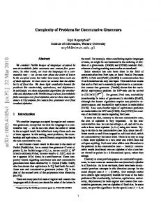
Simplifying the rule development process becomes as important, if not more, than providing an easy interface for rule selection and application. Non-parametric shape rules tend to be fairly straightforward to specify, at least when the shape rules are mainly geometrically with limited attributes. The user can simply draw the left-hand side and righthand side of the rule as shapes on a canvas. Labels may need to be assigned to points or other geometric elements through selection and assignment, and similarly for other attributes such as weights and colours. However, the process becomes more cumbersome when considering parametric shape rules. Stiny (1977) demonstrates parametric shape rules for the Chinese ice-ray lattice grammar. Vertex points of a triangle, quadrilateral or pentagon are expressed using fixed and parametric coordinates. Additional constraints on these parametric coordinates are also identified (Figure 1). Specifying both parameters and constraints complicates the process of specifying parametric shape rules.
Fortunately, most implementations of parametric shape grammar interpreters (PSGIs) rely on a graphbased representation (Grasl and Economou 2013; Wortmann 2013; Strobbe et al. 2015) which avoids the necessity to explicate coordinate parameters. Instead, constraints can be specified by drawing segments in parallel or of equal length (Grasl and Economou 2013). For example, a square has four
444 | eCAADe 35 - SHAPE GRAMMARS - Volume 2
sides, with parallel opposing sides, of equal length and, additionally, two diagonals of equal length. However, using a graph-based PSGI for Stiny’s Chinese ice-ray lattice rules does not pre-empt all constraint explications. As another example, Figure 2 shows a parametric shape rule from Duarte’s (2005) Malagueira grammar. Parametric coordinates are omitted, nevertheless, numerous control conditions are identified. Note that procedural grammars (Müller et al. 2006) offer relatively straightforward support for such rules but, instead, complicate the rule development process for designers as they are required to possess programming skills and painstakingly script and edit the procedural rules, thereby fracturing the design process and graphical interaction. As such, we do not consider procedural grammars as a solution to the problem and instead are interested in an approach that is more graphically interactive. Nevertheless, we recognise that not everything can be graphically depicted and that additional expressions, such as simple control conditions (e.g., Duarte 2005) or rule constraints, mainly expressed as (in)equalities, may remain necessary. In this paper, we aim to, on the one hand, identify a number difficulties that may arise when developing rules and, on the other hand, present solutions for graphical rule specification that can serve to overcome these difficulties. Our motivation comes from an active development of a design grammar using railway station design as a demonstration study. We present examples where drawing shape rules and augmenting these with control conditions or rule constraints offer insufficient support for the rules’ intricacies. We propose conventions for drawing and specification that support the explication of these exemplar shape rules, aiming not to overly complicate the drawing and specification process. We borrow from other authors where appropriate, for example, Duarte (2005) includes specifications of lengths of line segments in shape rules simply adopting normal dimensioning conventions in architectural drawings (Figure 2).
Figure 1 A constrained, parametric shape rule splitting a triangle into a triangle and a quadrilateral by placing a single line between two of the original triangle’s edges.
Figure 2 Rule dissecting an outside zone into yard and sleeping zones (after Duarte 2005, p. 359). The rule drawing illustrates the (parametric) specification of lengths of line segments. Control conditions referring to these lengths are also specified.
PARAMETER CONSTRAINTS Let us reconsider Stiny’s (1977) Chinese ice-ray lattice grammar. Each rule allows for a convex polygon, whether a triangle, quadrilateral or pentagon, to be split into two new convex polygons by placing a single line between two of the original polygon’s edges. In the case of the pentagon, these polygon’s edges may not be adjacent, in order to avoid the creation of a hexagon. Stiny (1977) expresses the polygonal vertex points using fixed and parametric coordinates and identifies a few additional constraints: 1. A rule only applies if the polygonal area is greater than some specified minimum value. 2. Each polygon includes a point near the centroid of the polygon, specifically, at a distance equal to the radius of the greatest circle contained in the polygon and centred on the centroid, and multiplied (scaled) by the area of
this circle over the area of the polygon. 3. The absolute difference between the areas of the two polygons arising from the splitting rule is less than some specified minimum value. The first condition ensures a minimum size (area) for a polygon to be split, while the second condition aims to prevent any rule from applying to a polygon that has already been split by the same or another rule. It is unclear why the second condition does not simply constrain the location of the point to coincide with the centroid of the triangle, rather than at a specific distance that is, on the one hand, proportional to the radius and area of the greatest circle contained in the polygon and centred on the centroid and, on the other hand, inverse proportional to the area of the polygon. The third condition ensures that the resulting polygons have more or less the same size (area).
SHAPE GRAMMARS - Volume 2 - eCAADe 35 | 445
These and other constraints are explicated in Figure 1: The first line of constraints aids in simplifying the final constraint, these may otherwise be omitted. The second line ensures the area of the triangle is greater than c. The third line simplifies the specification of the point as coinciding with the centroid, rather than at a specific distance of this centroid. The fourth and fifth line constrain the endpoints of the splitting line to coincide with two edges, though not with the vertices of these edges. The sixth and seventh line explicate the location of points within the new polygons. Finally, the last line limits the absolute difference between the two polygonal areas below a value d. We already stated that a graph-based PSGI may pre-empt the parametric specification of the coordinates of the polygon vertices. In addition, Stouffs (2017) demonstrates that the near-centroid point can be omitted in favour of labelling the polygon’s edges. Using descriptions (Stiny 1991; Stouffs 2016) instead of labels, the polygon’s edges can be identified using a parametric description (Figure 3). As such, except for the area condition, only a single parameter is needed within the left-hand-side of the shape rule. We will return to the area condition below. However, the same does not apply for the right-hand-side of the shape rule, as the endpoints of the splitting line are specified in terms of parameters t3 and t4, each constrained between 0 and 1 (excluding 0 and 1) with respect to the endpoints of the respective edges. Stouffs and Wieringa (2006) offer an implementation of the Chinese ice-ray lattice grammar where the endpoints of the splitting line are further constrained to lie between a (user-specified) minimum and maximum parameter value, e.g., 0.35 and 0.65 where the edge’s endpoints have values 0 and 1. Instead, the absolute difference constraint between the two polygonal areas is ignored in the implementation. The actual parameter value of the endpoint is simply randomly selected by the system. In addition, they suggest a graphical notation using a parallel line to the edge with two marks identifying the allowed interval (Figure 3).
446 | eCAADe 35 - SHAPE GRAMMARS - Volume 2
Stouffs and Wieringa’s (2006) implementation distinguishes the polygon boundaries (line segments) as well as the polygon surfaces (plane segments). In fact, as they adopt an object-oriented approach in which subshape detection is of no concern, rule application only requires the identification of the polygon (surface). The boundary elements are maintained solely for the purpose of dimensioning and structurally analysing the design. For our purpose, the identification of the plane segments serve the area constraints (Figure 3), though, in principle, having the description assigned only to the plane segment, and not the boundary segments, is sufficient, though not efficient from an implementation point of view (Stouffs 2017).
Figure 3 The shape rule of Figure 1 redrawn for a graph-based PSGI including (parametric) descriptions. The rule illustrates how both endpoints of the splitting line are constrained within a bounded section of the respective polygon’s edge.
Figure 4 Variations on the shape rule of Figure 3 using the void predicate and limiting the splitting line to connect only the two longest edges: (above) the lengths of the line segments are compared; (below) the shortest line predicate is adopted. Note that the constraint comparing both areas is omitted.
PREDICATES
Figure 5 Two variations of a same rule adding a perpendicular line segment to a single maximal line (specified using the maxline predicate), with proportional length (above) and fixed length (below).
Certainly, the approach illustrated in Figure 3 is far from the only one to reduce the complexity of the rule specification and its parametric constraints. Liew (2004) offers an alternative approach using a zone descriptor specifying a void predicate function prescribing the area to be devoid of any shape elements. Unfortunately, while it avoids a description to be required in the left-hand-side of the rule, labels or descriptions may still be necessary in the right-handside of the rule in order to implement the area constraint, unless such constraint would be omitted. However, there are other situations where a predicate may be useful. Consider we want to constrain the triangle splitting rule such that the splitting line splits the two longest boundary lines, avoiding the shortest edge. We could indicate the length of all three boundary lines and specify constraints identifying the shortest line (Figure 4 above). Alternatively, we could adopt a shortest line predicate identifying the shortest edge (Figure 4 below). Beirão (2012) similarly considers a rule (or pattern) that identifies the longest line among a set of lines.
ments. The former can be considered to imply no description as well, as descriptions can be deemed parametric labels. Figure 6 illustrates the use of both predicates in a very simple grid and rule-based room layout procedure. The first rule (Figure 6 above) considers a rectangular space defined both by a plane segment without label and boundary line segments and defines it as a room with label ”Ri ” (i being the room index). The second rule (Figure 6 below) considers a previously defined room and an adjacent, unassigned space and assigns the space to the room, adding the room label to the space and removing the boundary line segment between both spaces. The use of the no_line predicate ensures that a rule only applies to a single grid cell, not a combination of two or more grid cells. Note that the two rules in Figure 6 only allow for combining cells in either a horizontal or vertical sequence, not both.
RAILWAY STATION CASE STUDY In our railway station design case study, we’ve encountered similar situations requiring for parameter constraints and predicates. In the context of an axial layout, we’ve considered a rule that adds a perpendicular line segment to an existing line. Figure 5 shows two variations of a same rule with quite different results. Both rules specify a single maximal line using the maxline predicate as the left-hand-side shape. In the first rule (Figure 5 above), the perpendicular line segment is only geometrically defined with its length proportional to the matching line segment. In the second rule, the length of the perpendicular line segment is differently defined, in Figure 5 (below) as a fixed length, but it can also be defined as a function of other information provided. Other practical predicates may be no_label and no_line. The latter is conceived as a variant of void that applies only to line segments, not plane seg-
TOPOLOGICAL VARIATIONS Stouffs and Janssen (2017) suggest the use of shape grammars to generate relevant 3D building data from 2D urban plans that can serve to analyse and assess such urban plans with respect to different criteria, requirements and targets. Proposed rules include subdividing plots based on a targeted plotsize range, and generating towers whose height and number of floors is guided by a specified Gross Plot Ratio or Floor Area Ratio (Janssen et al. 2016). This means that the number of subdivisions or the number of floors is initially unknown and thus cannot be incorporated or drawn into the shape rule. While constructing alternative shape rules for different numbers of floors would be undesirable, it is possible to iteratively add any number of floors using just
SHAPE GRAMMARS - Volume 2 - eCAADe 35 | 447
a few (three) rules: an initialisation rule, an iteration rule, and a termination rule (Figure 7).
The initialisation rule (Figure 7 top) determines the number of parts, n, by comparing the average length l1 + l2 of the opposite sides of the quadrilateral, , to 2 l1 + l2 a target length lt : n = b + 0.5c. Addition2lt ally, it creates the first quadrilateral part by adding a single line segment at the appropriate distance(s) from the starting segment. The descriptions ”repeat” and ”n− 2 times” are added to the starting and new segment, respectively. n− 2 reflects on the fact that the last line segment creates two quadrilateral parts at once. The iteration rule (Figure 7 middle) reads the required distance(s) from the previous quadrilateral part in order to create one more part, adding a new line segment and moving the descriptions one segment over while, at the same time, reducing the number by one. Finally, the termination rule (Figure 7 bottom) only applies when n has become zero and removes the descriptions. While perfectly practical, it may be far from efficient. Generating a simple massing with floors, of a high-rise building, would require at least one rule application per floor. Speeding up the process could be achieved by adding a fourth rule to create a particular number of floors at once. For example, as long as the number of floors still to be created is larger than 10,
448 | eCAADe 35 - SHAPE GRAMMARS - Volume 2
a single rule could apply that adds 10 floors and reduces the number of floors to be created by 10. Once below 10, each remaining floor could be created individually by the existing rule. Additional rules could be added to create other, smaller or larger, numbers of floors, further reducing the number of rule applications needed to generate a single building. Instead, we can conceive of a single rule, and its graphical depiction, that can generate any number of floors in a single application (Figure 8). Only the first and last quadrilateral parts are fully drawn. They are tagged, respectively, #1 and #n, with their lengths also specified. In between the first and last segment tags, three dots stand for any number of segments to complete the segmentation into n parts. We use the # symbol to indicate the tagging in order to distinguish the tags from labels or descriptions. Obviously, the actual representation of the right-hand-side of the shape rule would require some form of a shape schema. However, here we are only concerned with the graphical depiction of such a rule and with the ease of use to conceive and elaborate such a rule. We are not concerned with the actual implementation, though we argue that devising the necessary shape schema should not be overly complicated.
Discussion Considering this ability to identify any number of parts in one rule, one may be eager to extend this approach to other contexts, such as the number of sides of a polygon. As in Stiny’s Chinese ice-ray lattice grammar, rules may apply to a number of different kinds of polygons, e.g., triangles, quadrilaterals and pentagons. If we can conceive of a way to graphically identify a polygon with any number of sides (with restrictions), we could simplify the rule set. Let us consider an example from the railway station case study. When designing an end station, we may have a number of parallel rail tracks ending at the station, though, while some tracks may end at the same linear point, other tracks may end earlier (or later). The shape of the end platform is then strongly defined by the linear end points of the various tracks with
Figure 6 Two rules assigning rooms (by index) to spaces in a grid layout. The second rule allows grid cells to be combined into larger rooms.
Figure 7 A set of three rules splitting a quadrilateral into a series of quadrilaterals where the number is defined by comparing the average length of opposite sides of the quadrilateral to a target length. The segmentation is achieved by splitting the respective sides in equal length parts.
access to the various side and/or island platforms, while the station building itself may define a single linear boundary (Figure 9). Considering that we can always define the end platform as a polygon, however complex, it would be advantageous if we could have a rule that takes any polygon as the left-hand-
side shape to operate on it. However, it would be nearly impossible to graphically represent the rule or its left-hand-side. Instead, a symbolic rule would be more appropriate representing the polygon as a symbol or object, irrespective of its actual shape.
Figure 8 The graphical depiction of a single rule that is able to achieve the same result as the rule set in Figure 7.
SHAPE GRAMMARS - Volume 2 - eCAADe 35 | 449
While a combination of (graphical) shape rules and symbolic rules may come in handy, here, we argue strictly for shape rules that can be graphically represented, even if we allow for simple topological variations. Specifically, we would like to argue that graphically identifying a polygon with any number of sides may complicate rather than simplify the rules, as it would become much harder to identify to which kind of polygons the rule applies and what the result of rule application would be. Stiny’s rules are actually very simple and clear. One can immediately understand these apply to triangles, quadrilaterals and pentagons and also what the effect of rule application is on the respective polygon. Such would not be the case for a single rule applying to different kinds of polygons, as the user would need to carefully check the constraints and conditions in order to understand whether triangles, quadrilaterals or other polygons are included. In the case of the potentially complex shape of an end platform, we would rather consider a small collection of rules that define partial end platforms, then join the partial end platforms together into one complete end platform, thereby identifying the platform boundaries, including with the island and side platforms. For example, in Figure 10, the top rule identifies the platform boundaries of any adjacent rail tracks with the same linear end points (using the maxline predicate) and the station boundary fronting the rail tracks, and defines a partial end platform between these two boundaries. The partial end platform is defined both as a polygon of line segments and as a coinciding plane segment with label “ep”.
450 | eCAADe 35 - SHAPE GRAMMARS - Volume 2
The middle rule in Figure 10 is conceived as a general rule that takes two interlocking (partial) polygons of line segments, where both coincide with a labelled plane segment, e.g., with label “ep”, and replace it with a single (partial) polygon of line segments bounding the combined plane segment. Finally, the bottom rule in Figure 10 ensures that in case of an island platform that extends into a side platform, because one rail track extends beyond the other, the end platform area is reduced to allow for the full side platform width (indicated by wp from the centre of the rail track).
Note that in the middle rule of Figure 10, the label is parametrised as a description, even if the constraint currently limits the parameter only to the value “ep”. However, it would be very easy for the designer to generalise the rule and include other label/description values. Note as well that the middle and bottom rule assume that the width of an island platform is always smaller than twice the width of a side platform. If, however, the width of an island platform is exactly twice the width of a side platform, then, the bottom rule becomes obsolete, while a new rule would be needed to allow two (partial) polygons of line segments that touch (rather than overlap), where both coincide with a labelled plane segment sharing the same label, to be joined. In case the width of an island platform may exceed twice the width of a side platform, other rules may be additionally necessary. Finally, we would like to add that, following the same line of thought, we only conceive of rules allowing
Figure 9 The polygonal shape of an end platform resulting from rail tracks with different linear end points.
Figure 10 Three rules defining partial end platforms (top), then joining the partial end platforms together into one complete end platform (middle), thereby identifying the platform boundaries, including with the island and side platforms (end).
for a one-dimensional topological variation, that is, for repeating elements, one-dimensionally, any number of times. In case we need to subdivide plots two-dimensionally, we suggest a first segmentation in one dimension, followed by segmenting each part in the other dimension. Obviously, there is some subjectivity involved in all these arguments and in our choice for what we allow for and what not. However, we would be happy to have this discussion and will further contribute with the continuous development and elaboration of the (limited) railway station grammar. Our ultimate aim is to achieve an implementation of the grammar, including all the solutions here presented.
CONCLUSION We have identified different examples where drawing shape rules and only augmenting these with control conditions or constraints lead to overly complex rule formulations or offer insufficient support for the rules’ intricacies. We have presented examples of graphical constraints, e.g., indicating segment lengths or boundary intervals, and of predicate functions acting as constraints, as well as of topological variations expressed graphically. Some examples have been borrowed from other authors and extended where appropriate. As we acknowledge that others may have addressed similar issues, whether implicitly or explicitly, we also acknowledge that our investigation is far from complete. We consider this as an active discussion, one that we will continue to engage in and that we invite others to contribute to as well. We envision the discussion to include both the vocabulary of (graphical) conventions and techniques and the extents and limitations of these techniques. Specifically, with respect to topological variations, we have indicated where we would opt to limit this technique. While we have limited the discussion to graphical depictions, we do intend to implement most or all of the suggested techniques, at some point.
ACKNOWLEDGMENTS This work received some funding support from Singapore MOE’s AcRF start-up grant, WBS R-295-000129-133. The second author also benefited from a China Scholarship Council grant.
REFERENCES Beirão, JN 2012, CItyMaker: designing grammars for urban design, Ph.D. Thesis, TU Delft Beirão, JN and Duarte, JP 2009, ’Urban design with patterns and shape rules’, in Stolk, E and te Brömmelstroet, M (eds) 2009, Model Town, Using Urban Simulation in New Town Planning, SUN, Amsterdam, pp. 148-165 Beirão, JN, Duarte, JP and Stouffs, R 2009, ’Grammars of designs and grammars for designing – grammar based patterns for urban design’, in Tidafi, T and Dorta, T (eds) 2009, Joining Languages, Cultures and Visions, Université de Montréal, Montreal Downing, F and Flemming, U 1981, ’The bungalows of Buffalo’, Environment and Planning B: Planning and Design, 8(3), pp. 269-293 Duarte, JP 2005, ’A discursive grammar for customizing mass housing: the case of Siza’s houses at Malagueira’, Automation in Construction, 14, pp. 265275 Grasl, T and Economou, A 2013, ’From topologies to shapes: parametric shape grammars implemented by graphs’, Environment and Planning B: Planning and Design, 40(5), pp. 905-922 Janssen, P, Stouffs, R, Mohanty, A, Tan, E and Li, R 2016, ’Parametric modelling with GIS’, in Herneoja, A, Österlund, T and Markkanen, P (eds) 2016, Complexity & Simplicity, Vol. 2, eCAADe, Brussels, pp. 5968 Knight, TW 1999 ’Applications in architectural design, and education and practice’, NSF/MIT Workshop on Shape Computation, Cambridge, MA Liew, H 2004, SGML: a meta-language for shape grammar, Ph.D. Thesis, MIT Müller, P, Wonka, P, Haegler, S, Ulmer, A and Van Gool, L 2006, ’Procedural modeling of buildings’, ACM Transactions on Graphics, 25(3), pp. 614-623 Stiny, G 1977, ’Ice-ray: a note on the generation of Chinese lattice designs’, Environment and Planning B: Planning and Design, 4(1), pp. 89-98 Stiny, G 1980, ’Introduction to shape and shape grammars’, Environment and Planning B: Planning and Design, 7(3), pp. 343-351
SHAPE GRAMMARS - Volume 2 - eCAADe 35 | 451
Stiny, G and Gips, J 1972, ’Shape grammars and the generative specification of painting and sculpture’, Information Processing, 71, pp. 1460-1465 Stiny, G and Mitchell, WJ 1978, ’The Palladian grammar’, Environment and Planning B: Planning and Design, 5(1), pp. 5-18 Stouffs, R 2017 ’A practical shape grammar for Chinese ice-ray lattice designs’, 2nd International Workshop on Cultural DNA, Daejeon, South Korea Stouffs, R and Janssen, P 2017, ’A rule-based generative analysis approach for urban planning’, in Lee, J-H (eds) 2017, Morphological Analysis of Cultural DNA, Springer Nature, Singapore, pp. 125-136 Stouffs, R and Wieringa, M 2006 ’The generation of Chinese ice-ray lattice structures for 3D facade design’, Conference Proceedings of the Joint International Conference on Construction Culture, Innovation and Management (CCIM), Dubai, pp. 416-424 Strobbe, T, Pauwels, P, Verstraeten, R, De Meyer, R and Van Campenhout, J 2015, ’Toward a visual approach in the exploration of shape grammars’, Artificial Intelligence for Engineering Design, Analysis and Manufacturing, 29(4), pp. 503-521 Wortmann, T 2013, Representing shapes as graphs, Master’s Thesis, MIT Çagdas, G 1996, ’A shape grammar: The language of traditional Turkish houses’, Environment and Planning B: Planning and Design, 23(4), pp. 443-464
452 | eCAADe 35 - SHAPE GRAMMARS - Volume 2