John Vallerga, Jason McPhate, Anton Tremsin .... Medipix2 ROIC (Llopart & Campbell 2003; Vallerga et al. .... Abiad, R., & Hull, J. 2003, Nuclear Instruments and.
Astrophysics and Space Science DOI 10.1007/sXXXXX-XXX-XXXX-X
The current and future capabilities of MCP based UV detectors John Vallerga, Jason McPhate, Anton Tremsin and Oswald Siegmund
c Springer-Verlag ••••
Abstract At the heart of future space-based astronomical UV instruments will be a sensitive UV detector. Though there has been a dearth of new UV mission opportunities, detector development has continued. Improvements have been made in spatial resolution, dynamic range, detector size, quantum efficiency and background. At the same time the power and mass required to achieve these goals have decreased. We review the current capabilities of microchannel plate based detectors, both in the laboratory and aboard current on-orbit spacecraft . We also discuss what can be expected from the next generation of UV detectors over the next decade. Keywords detectors: ultraviolet — detectors: microchannel plate 1 Introduction Imaging, photon counting detectors that use microchannel plates (MCPs) have been the detector of choice for most UV astronomy missions over the last two decade. In fact, the detectors on the SOHO, EUVE, IMAGE, FUSE(Sahnow et al. 2000) , ALEXIS, GALEX(Siegmund et al. 2004) , ROSSETA-ALICE, and New Horizons-ALICE (Stern et al. 2007) missions represent over 200+ detector years in space without a failure (of the detectors). The Hubble servicing mission in the fall of 2008 will install another UV instrument, the Cosmic Origins Spectrograph (COS)(Green et al. 2003) . John Vallerga, Jason McPhate, Anton Tremsin and Oswald Siegmund Space Sciences Laboratory, University of California, Berkeley, Berkeley, CA, 94720-7450, USA
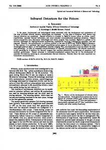
Fig. 1.— COS-HST detector head with two adjoining 85 x 10 mm fields of view. Z stacks of three MCPs were curved to match a 0.6m radius to match the focal plane curvature. Cross delay line image readout anodes were used. The COS MCP detector (Vallerga et al. 2002) was state of the art when it was fabricated in 2002 (Fig 1.). The format of the COS detector has two segments, each 85 x 10 mm active area, separated by 9 mm. Each detected photon event x,y position was digitized to 14 x 10 bits which could be transferred to the ground as either a photon event list or a 2-d image ( 16384 x 128 pixels). The spatial resolution in the spectral (long) dimension is 25 µm FWHM while the imaging (short) dimension has a resolution of 50 µm FWHM. The event electronics has a deadtime of 7.4 µm per event, resulting in a deadtime fraction of 10% at an input count rate of 15,000. Since the delivery of the COS detector, our group at the Space Sciences Laboratory has been improving the space-based capabilities of MCP detectors including resolution, deadtime, uniformity, lifetime, power and mass. Some of these improvements are the result of better MCPs from the manufacturer. Other improvements result from the adoption of new electronic technologies
2
1 MHz, though in practice 200 kHz at 10% deadtime is typically achieved.
Fig. 2.— Readout anode types. The XDL consists of 2 serpentine delay lines and uses 4 amplifiers to determine the time pulse arrival time difference. The XS anode has many strips and amplifiers to measure the output charge centroid. The pixellated anode ASIC detects and counts events on a pixel scale (ASICs, FPGAs) while still others result from specialized careful design to fit the observational application (e.g. low power for a Pluto mission). Table 1 summarizes some of the standard performance parameters of the COS detectors as a baseline and compares them to what is currently feasible in a flight detector. There are certainly trade-offs among these performance parameters. For example, larger format size usually requires more mass, and higher input rates result in shorter MCP lifetimes for a fixed gain. Yet there are often design paradigm shifts that can improve certain parameters by orders of magnitude without sacrificing other key parameters. Below we discuss a few examples of these new designs, specifically better MCPs and readout technologies, and refer the reader to the references for more details.
2 MCP readouts MCPs amplify a single photoelectron from a photocathode into an exiting electron charge cloud whose centroid represents the position of the incoming photon. Fig. 2 shows three methods of determining the centroid of the electron cloud using a patterned anode: cross delay line (XDL), cross strip (XS) and pixellated readout integrated circuit (ROIC). The XDL anode (Siegmund et al. 1994) uses the temporal difference of the two charge pulses at either end of a delay line to determine a linear position in that axis. Though only 4 high bandwidth amplifiers are required to read out the x,y position of each event, large gains (≈107 ) are required to reach high spatial resolutions. Typical (but well tuned) XDL readouts can achieve resolutions of ≈ 20 µm FWHM. As more than one event on an XDL anode at the same time results in an incorrect position, the ultimate global count rate limit for an XDL detector is approximately
Fig. 3.— MCP flat field (zoomed to 1 x 1 mm) using a cross strip readout that resolves the MCP pores. The pores are 12µm on 15µm centers. In this example, the imaging spatial resolution would be limited by the pore spacing rather than the readout anode, but it is demonstrative of the capability of the new readout technologies that could be combined with MCPs of a finer pore pitch. The XS anode (Siegmund et al. 2003) has a charge amplifier stage on each strip, and the individually digitized event signals are centroided to determine the separate x and y positions. By dividing up the anode area into smaller strips, the capacitance of the electrodes, and hence the noise, is decreased, allowing lower gain operation even at better resolution. This capability of many (≈64) parallel amplifiers became possible with the advent of CMOS application specific integrate circuits (ASICs) with low noise and low power. XS anodes can be easily scaled to larger formats by just adding more amplifiers and ADCs, proportional to the linear size of the array. We have achieved spatial resolutions of the readouts of 5 µm at a gain of 5×10⁵, even resolving the MCP pores (Fig. 3). The ultimate photon spatial resolution would then be limited by the sampling of the MCP pore spacing. Event rates using XS anodes can be very high (> 1 MHz) if the digitization of the ASIC amplifier outputs is also massively parallel and the centroiding calculation is done with a digital pipelined architecture using field programable gate arrays (FPGAs) or digital signal processors.
The current and future capabilities of MCP based UV detectors
3
charge cloud over many pixels allows a very accurate sub-pixel determination of the event centroid, similar to the XS readout, but at lower gain. Fig. 4 demonstrates the improved resolution performance when operated in this mode, though sacrificing the GHz count rates to 200 kHz limit to avoid event collision between frame readouts. Pattern 5-6 is just resolved corresponding to 57 lp/mm using an MCP with 8 µm pore spacing.
3 MCP uniformity
Fig. 4.— Air force test pattern mask UV image (zoomed) taken with Timepix readout of a chevron MCP stack. The charge cloud of every event was sampled by the Timepix, centroided on sub-pixel scale, and rebinned to 4096x4096. Pattern 5-6 (57 lp/mm) is just resolved, consistent with the 8 µm pore spacing of the MCPs. The width of one bar of the 5-1 pattern is 16 µm. A recent development in MCP readouts is the Medipix2 ROIC (Llopart & Campbell 2003; Vallerga et al. 2004) . In this case, the anode is pixellated (256x256), with every 55 µm pixel containing an amplifier, discriminator and counter. Events with signals above a lower threshold of 1000 electrons are counted and integrated on chip. As the image is digital, it can be read out very fast, > 100MHz, allowing frame rates of 1 kilohertz with zero readout noise. Because the events are integrated on chip , individual event time tagging is lost, so event times are only accurate to the frame time. What is gained are phenomenal input rates, up to GHz rates. Of course, to operate at GHz rates for extended periods would quickly deplete the gain of the MCPs, unless the MCP can be operated at extremely low gain, on the order of 104 , which the low threshold of the Medipix2 discriminator allows. The Medipix2 pixel is a rather large (55 µm), as it was originailly developed for x and gamma ray imaging. The Timepix ASIC (Llopart 2007) is a modification of the Medipix2 that mostly changed the discriminator logic, allowing pulse amplitude determination for each event, rather than just counting. Using this facility and adjusting the detector parameters to spread the MCP
One of the consequences of the fabrication process for MCPs is image modulation related to the multifiber bundles. This is fairly typical of MCPs produced prior to 2000 and in particular for large area MCPs that are made by the block fabrication processes. Studies of the physical presentation of these MCPs show that there are distinct MCP pore misalignments and distortions at the multifiber boundaries. One resulting effect are changes of the local gain due to the pore distortions. In addition, the pore distortions produce changes in the direction of the emitted electrons at the output of the MCP which produce the observed apparent spatial deficit and excess of detected events across the multifiber boundaries (Fig. 5) . At high resolution (Fig. 3) the displacement and distortions of the pores at multifiber boundaries are clearly observed. MCPs produced by boule encapsulated fabrication have far less multifiber edge modulation than block fabricated larger size MCPs. Presumably this is because the misalignment and stress at multifiber boundaries is worse for block fabricated MCPs where the compression during high temperature fusing is predominantly in one direction rather than radial as in the case for a boule. Recent production efforts have attempted to resolve some of Table 1 Current MCP detector capabilities compared to the COS detector Parameter
COS
Current
Comment
Formats size (mm)
90×10
100×100
Spatial Resolution (µm FWHM)
25
8
MCP pore spacing limited
MCP gain
107
107 105 104
XDL XS Medipix2
Global Count Rate (kHz, 10% deadtime)
15
200 1000 1000000
XDL XS Medipix2
Power (W)
37
1.1
Pluto-ALICE
Mass (kg)
33
0.66
Pluto-ALICE
4
Fig. 5.— Flat field images of two different detectors with two differenent sets of MCPs. On the left is a deep flat field of a 10 x 10 mm section of the COS detector showing the image distortion at the MCP multifiber boundaries. On the right is an optical image tube flat field (18mm diameter active area) using MCPs that had the multifibers fused using a boule encapsulated fabrication method that shows little of the multifiber distortion. these fabrication effects. Images obtained with smaller 33mm MCP stacks in XDL detectors (Fig. 5) show that recently produced boule fabricated MCPs have no observable multifiber modulation in their intensity maps. Acknowledgements The studies presented here were obtained through a series of NASA grants and contracts, but the data was compiled under NASA grants NAG5-12710 and NAG5-9149. The Medipix/Timepix readout development was supported by NSF under AURA AST-0132798-SPO6 (AST-0336888)
The current and future capabilities of MCP based UV detectors
References Green, J. C., Wilkinson, E., & Morse, J. A. 2003, Proc. SPIE, 5164, 17 Llopart, X., & Campbell, M. 2003, Nuclear Instruments and Methods in Physics Research A, 509, 157 Llopart Cudie, X., Doctoral Thesis, Mid-Sweden University, Sundsvall, Sweden, 2007 McPhate, J. B., Siegmund, O. H., Gaines, G. A., Vallerga, J. V., & Hull, J. S. 2000, Proc. SPIE, 4139, 25 Sahnow, D. J., Gummin, M. A., Gaines, G. A., Fullerton, A. W., Kaiser, M. E., & Siegmund, O. H. 2000, Proc. SPIE, 4139, 149 Siegmund, O. H., et al. 1994, Proc. SPIE, 2280, 89 Siegmund, O. H. W., Tremsin, A. S., Vallerga, J. V., Abiad, R., & Hull, J. 2003, Nuclear Instruments and Methods in Physics Research A, 504, 177 Siegmund, O. H. W., et al. 2004, Proc. SPIE, 5488, 13 Stern, S. A., et al. 2007, Space Science Reviews, 128, 507 Vallerga, J., Zaninovich, J., Welsh, B., Siegmund, O., McPhate, J., Hull, J., Gaines, G., & Buzasi, D. 2002, Nuclear Instruments and Methods in Physics Research A, 477, 551 Vallerga, J. V., McPhate, J., Mikulec, B., Tremsin, A., Clark, A., & Siegmund, O. 2004, Proc. SPIE, 5490, 1256
This manuscript was prepared with the AAS LATEX macros v5.2.
5