Stein J. Ryan, Arne Maus, Stein Gjessing. University of Oslo, PO Box 1080 Blindern, N-0316 Oslo, Norway. Email: {steinrya,arnem,steing}@ifi.uio.no. Abstract.
The Design of an Efficient Portable Driver for Shared Memory Cluster Adapters Stein J. Ryan, Arne Maus, Stein Gjessing University of Oslo, PO Box 1080 Blindern, N-0316 Oslo, Norway Email: {steinrya,arnem,steing}@ifi.uio.no
Abstract
fails, another computer can step in so that the cluster as a whole remains unaffected from a correctness viewpoint although performance might drop.
We describe the design of an efficient portable driver for shared memory interconnects. The driver provides a foundation for interfacing to commodity software like clustered database servers. We present performance figures for a driver implementation that uses SCI through the PCI bus on standard PCs running Windows NT.
In order to realize scalability and resilience, we need highly efficient internode communication services (otherwise scalability will suffer) while at the same time making those services robust with regard to system failures (otherwise resilience will suffer). Combining robustness with high performance is challenging. A high level of robustness can easily hurt performance unless great care is taken in the design and implementation of the communication services. With shared memory interconnects, this problem has a somewhat different flavour than in traditional messagepassing interconnects. With a shared memory interconnect, communication between computers can be divided into two phases.
Keywords: Clustering, Shared memory, SCI.
1 Introduction With the rapid advances in microprocessor design, the cluster of workstations is emerging as a cost effective solution to high-end processing needs [1]. A cluster consists of a number of autonomous, loosely coupled computers. Proprietary interconnects like high-speed memory buses are not required for their operation. Clusters will instead use standard communication technologies like Ethernet, or (more recently) IO-bus based shared memory interconnects like the Dolphin SBUS-SCI [2] and PCI-SCI [3] [4] adapters, ServerNet [5] and the DEC Memory Channel [6]. A cluster has two highly desirable properties:
1. A computer makes a chunk of local memory available to other computers. Using their cluster adapters, the other computers can map the chunk into their physical address space. They can then set up virtual mappings so that programs can access the remote chunk directly from user mode. Special driver software in each computer will manage the cluster adapter hardware and the connections to remote chunks.
• Scalability means that the cluster can grow to accomodate increasing needs for processing power by simply adding more computers to the cluster. This of course hinges on the software’s ability to take advantage of the added computers, and is not trivial. However, it is hoped that this software complexity can be hidden inside commodity software like database servers.
2. Programs running in user mode on different nodes then communicate through the chunks using the load and store instructions of the CPU. This is referred to as Programmed IO (PIO).
We see that the driver need not be involved in the actual • Resilience means that the computers in the cluster transfer of data between user mode clients on different can act as backups for each other. If one computer machines. The driver is only involved initially in setting 1
up access to shared chunks of memory. Once the participating user mode clients have mapped remote chunks into their virtual address spaces, the actual exchange of data is done directly from user mode by reading from and writing into the chunks. This effectively moves the driver out of the critical path. We don’t have to invoke the driver on every data transfer, thus minimizing the number of costly transitions between kernel mode and user mode. As messages grow in size, we will eventually want to use DMA, and we are back to a traditional situation where the driver will be invoked for every message. An interesting question is then: How large should a message be before it is better to move it by DMA than by PIO. We have conducted a performance analysis which answers this question for one specific platform. The user mode clients need to be aware of the fact that remote memory may go away at any time if the remote memory host should fail. load and store are normally regarded as operations that can’t fail, but clients of remote memory need to observe that remote memory load and store operations may in fact fail. This complicates the logic in the user mode client, and requires some kind of checkpoint scheme where all remote memory operations prior to a certain checkpoint may be checked for success. However, the complexity of this checkpoint logic will typically be hidden in the front ends of commodity software (ie database front end), out of view from application programmers.
Cluster adapter software Application client using shared memory User mode
Usermode API (USRAPI)
Application client using TCP/IP
IOCTL
Kernel mode Parameter validation for USRAPI
Interconnect Manager (ICM)
TCP/IP driver using shared memory
Cluster adapter hardware
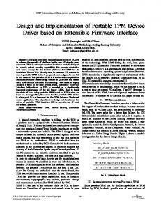
Figure 1: An overview of the cluster adapter software design. • A DMA engine is required in order to transfer large amounts of data in parallel with computation.
In the following we describe the design of a portable driver which implements these services on the Windows NT operating system. The driver uses the Dolphin PCISCI cluster adapter to access the global SCI address space shared by all the interconnected computers. A PC equipped with this cluster adapter can export selected parts of its local memory to the global SCI address space. Other nodes can then import selected areas from that global address space into their local address space, gain2 Design ing access to a shared region of memory hosted by some other node. An overview of the driver software is preIn light of the introduction, it is clear that programs com- sented in figure 1. municating through a shared memory interconnect need a The software is structured around an Interconnect Mannumber of supporting mechanisms. ager (ICM), which offers an abstraction of the cluster adapter to kernel mode clients (i.e. other drivers). As indi• First of all we need a mechanism for mapping remote cated in figure 1, the services of the ICM can for example memory into the address space of a user program. be used by a transport driver so that existing software can • A remote interrupt mechanism is needed if we want take advantage of the interconnect through established into implement a blocking form of message passing terfaces like TCP/IP. We have not written such a TCP/IP driver yet. through shared memory. The services of the ICM are made available to programs • A checkpoint mechanism is required to detect com- running in user mode through a parameter validation layer munication errors on the shared memory intercon- which shields the ICM from erroneous requests from user nect. Robust systems should update shared memory programs. In contrast, kernel mode clients are trusted to observe the preconditions of the ICM routines. Consein a transactional fashion using checkpoints.
M hosted by computer B, the RMM of A will send a request to the LMM of B. The LMM of B responds with the SCI address of M . Once the RMM of A has the SCI adLocal memory manager DMA service dress of M , it can map M into the local physical address space by setting up an address translation mechanism on its cluster adapter. Any access by A to this physical address range will then be serviced by the cluster adapter of Interrupter Remote memory manager A mapping the request into an SCI request for B. One such access takes about 2.6µs. This is high compared to local memory. However, the cluster adapter contains a pipelining mechanism [3] allowing large PIO transfers (consisting of many requests) to be done very efficiently. Figure 2: The modules of the Interconnect Manager. The LMMs and RMMs of the machines in a cluster communicate using a simple RPC protocol. This proquently, requests from kernel mode clients bypass the pa- tocol uses SCI packets targeted at a special node ID in the receiver. Packets send by A to the special node ID rameter validation layer for maximum efficiency. Programs use the services of the ICM through the US- of the adapter in B are simply stored in a ring buffer in RAPI library which issues IOCTLs down to the parame- B’s memory where they trigger an interrupt. These SCI ter validation layer. The IOCTL mechanism is a form of packets are known as software packets and are special to message passing from user mode to kernel mode allowing the Dolphin PCI-SCI adapter. In response to a software a user mode program to send requests to a driver running packet interrupt, the LMM of B retrieves the software in kernel mode. The parameter validation layer exists as packet from the ringbuffer and carries out the procedure a driver in kernel mode and invokes the matching routine call requested in the packet. The LMM then sends the rein the ICM in response to the IOCTL requests from US- sult of the procedure call back to the RMM of A using a software packet. RAPI. The software packet mechanism lets us use SCI as a The ICM can be divided into four modules as seen in traditional buffered and interrupt driven communication figure 2, each responsible for a particular service. In the channel. This allows us to send information to recipients following we discuss each service and the rationale beidentified only by node ID. Such a hardware mechanism hind it. is required as a basis for the communication between the LMM and RMM of different machines. Interconnect Manager (ICM)
2.1 Local memory manager The local memory manager (LMM) lets us export chunks of local memory into the SCI address space so that other nodes may access it. Only memory that has been explicitly exported is available to other nodes. The LMM maintains a list of the local memory chunks that have been exported to SCI, and responds to queries for the SCI address of chunks.
2.3 DMA service
The DMA service allows for high bandwidth transfers between the local address space and the global SCI address space. The transfers are done by a scatter-gather DMA controller which interrupts the CPU on completion. This leaves the CPU free to do other things while the DMA controller transfers data. Setting up a DMA transfer involves a lot of overhead. Much of the overhead stems from the fact that a DMA 2.2 Remote memory manager transfer is initiated from kernel mode and not directly The remote memory manager (RMM) lets us import a part from user mode. Starting a DMA transfer from a program of the SCI address space into the local physical address requires a transition from user mode to kernel mode. This space. If computer A wants to connect to a memory block is quite expensive in most operating systems. Clearly,
1. The entry phase covers the transition from user mode to kernel mode and locking down in physical memory the local user buffer which will be the source or target of the DMA operation.
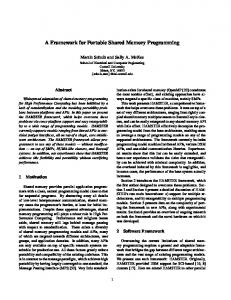
Overhead of medium size DMA transfers 80000
70000
60000 Time (CPU cycles)
transferring smaller blocks of data should be done directly from user mode by PIO. In order to analyze the sources of overhead in a DMA transfer, we divide DMA transfers into five consecutive phases:
50000
exit schedule transfer setup entry
40000
30000
20000
10000
2. The setup phase covers constructing the DMA controller’s scatter-gather list and establishing any required IO mapping of the user buffer in the IO MMU (if any).
0 0
2000
4000
6000
8000 10000 12000 Message size (bytes)
14000
16000
18000
3. The transfer phase covers the time spent by the Figure 3: The accumulated duration of DMA phases for DMA engine to complete the transfer once it has medium size transfers. started running. 4. The schedule phase covers the time interval between figure also displays the transfer time using PIO, showing the DMA completion interrupt and the start of the that we could have transferred roughly 5K by PIO using DMA completion interrupt handler. only the DMA overhead cycles. Note that DMA transfers 5. The exit phase starts on entry to the DMA comple- initiated directly from kernel mode have less overhead — tion interrupt handler and extends until the user pro- the 5K threshold is specific to transfers initiated from user gram thread has resumed running (the user program mode. has been waiting for the DMA operation to complete The motivation behind DMA is to allow computation in and must be unblocked by the DMA completion in- parallel with data transfer. If using the DMA engine from terrupt). user mode costs roughly 20000 CPU cycles of overhead as We measured the duration of the different DMA phases in CPU cycles on a 133 MHz Pentium-based PC. To do this, we took advantage of the 64-bit CPU cycle counter in the Pentium processor which is incremented by hardware on every clock cycle. The duration of each DMA phase was measured for transfers of different size from user mode. Figure 3 shows the accumulated duration of each consecutive phase. As expected, the duration of the transfer phase grows linearly with transfer size. All the other phases are fairly constant in duration and represent overhead. Figure 4 shows overhead dominating the transfer time for small transfers. Figure 5 is equivalent to figure 3 except that the transfer phase has been left out, thus showing only the phases that represent overhead. This tells us which phase represents the most overhead. We see that entering and leaving kernel mode is a considerable part of the overhead. The
indicated in figure 5, a program could just as well transfer the data by PIO if the message is less than 5K in size. In that case, using PIO means less work for the CPU than using DMA. Due to the fairly constant overhead per message when using DMA, the achievable throughput will increase with the message size. Figure 6 shows throughput from user space for both DMA and PIO. All the graphs shown here are very hardware dependant and particularly sensitive to implementation details of the host bridge that connects the PCI bus to the memory bus. The graphs shown were obtained on a 133MHz Pentium using the Intel 430HX host bridge. We note that PIO consistently outperforms DMA by a significant amount. The host bridge seems to offer better service to a CPU pushing data onto a local cluster adapter than to a cluster adapter DMA controller pulling data out of local memory.
Overhead of small DMA transfers
Cumulative overhead of DMA transfer excluding transfer phase. PIO transfer time.
40000
25000
35000 20000 pio exit schedule setup entry
Time (CPU cycles)
Time (CPU cycles)
30000
25000
20000 exit schedule transfer setup entry
15000
15000
10000
10000 5000 5000
0
0 0
500
1000
1500 2000 Message size (bytes)
2500
3000
3500
0
2000
4000
6000
8000 10000 12000 Message size (bytes)
14000
16000
18000
Figure 4: The accumulated duration of DMA phases for Figure 5: The accumulated duration of DMA phases when small transfers. ignoring the transfer phase. Transfer time using PIO.
2.4 Interrupter
set the most significant bit to zero so that the second write would trigger an interrupt. This should be a useful feature in master-slave parallel programs where a master expects a number of answers from its N slaves after presenting them with a task. By associating a single flag location with the answers and initializing that location to the value 1 − N , the master will receive a single interrupt when all slaves have signalled the completion of their task by incrementing the flag. Interrupts involve a transition into the kernel, and should be considered expensive. The interrupter allows user programs to wait for an interrupt from any one of a number of flag locations. Using a tracer we have measured the typical interrupt latency of the Windows NT kernel to roughly 6000 CPU cycles (ie about 50µs on a 133 MHz machine). Reflecting this interrupt up to user space adds another 12000 cycles resulting in a best case total interrupt latency of about 135µs for a user program. Clearly, programs that use shared memory as a medium for interrupt-driven message passing will not take full advantage of the low latency inherent in shared memory.
The interrupter allows a user program running on machine A to conditionally trigger an interrupt in machine B by writing to a part of the SCI address space through a specially configured address translation entry. All stores mapped to SCI through that address translation entry will result in an atomic increment of the value at the corresponding location in the target node. If the most significant bit in the old value was zero, this will trigger an interrupt in B. By modifying the initial values of these locations, B can control if other nodes will just increment a flag or interrupt as well. For example, by setting the initial value of a flag location in B to 0x7fffffff, only one interrupt will ever be generated because incrementing the flag will set the most significant bit. Subsequent writes will only increment the flag and not trigger an interrupt (until the counter eventually wraps around). In effect, the interrupt flag has automatically switched from interrupt mode to polling mode, allowing software in B to handle further signals from other nodes by spinning waiting for the flag to increment. Alternatively, the flag may be reset to its initial value in the interrupt handler, thereby immediately rearming the 3 Portability interrupt flag in favour of polling. Another scenario is to set the initial value of a flag to The software described here has been written in a mod(say) 0xffffffff. This would allow us to “gather” two inter- ular fashion. Operating system and hardware dependenrupts and process them as one. The first increment would cies have been isolated in separate source code modules.
Throughput for DMA and PIO
of the data transfer. We note that any interrupt processing by necessity involves the kernel, so interrupt driven mes50 sage passing through shared memory might still involve pio kernel transitions even though the message contents gets dma 40 written by user mode code directly into the memory of the recipient. The interrupter allows us to combine inter30 rupting with polling and also gathering of interrupts. This clearly has a potential for reducing the overhead. 20 We are currently developing an interface between our USRAPI and the Oracle Parallel Server (OPS). The Dis10 tributed Lock Manager of OPS is a prime candidate for exploiting the low latency offered through our USRAPI. 0 0 50000 100000 150000 200000 250000 300000 Message size (bytes) We are also experimenting with communication drivers (NDIS/TDI) that use the ICM from kernel mode. This allows existing software to use the cluster adapters through Figure 6: Throughput for DMA and PIO as a function of standard interfaces like TCP/IP. message size. Throughput (MByte/s)
60
For example, the Operating System Interface (osif) module isolates the other modules from the operating system. Porting amounts to reimplementing a few modules using the services of the target operating system and perhaps the mechanisms of a new cluster adapter. Defining the interface to the osif module is rather complex requiring detailed knowledge of several operating systems. Simply specifying a number of routines for memory allocation, synchronization etc is not sufficient because operating systems are organized into a number of run levels where all operating system services are not available at all run levels. For example, Windows NT does not allow allocating physically contiguous memory while servicing an interrupt. In order to define the osif module interface, we had to define our own abstract operating system including abstract run levels that map well to most popular operating systems. Each routine in the osif module was assigned a maximum abstract run level based on our knowledge about the restrictions in concrete operating systems exemplified by Windows NT and Solaris. The software is currently being ported to Solaris and UnixWare.
5 Acknowledgements This work is carried out as part of the OMI/ASCISSA research project. The authors would like to thank the development team at Dolphin Interconnect Solutions for their assistance.
References [1] Gregory F. Pfister. In Search of Clusters. Prentice Hall PTR, New Jersey 1995 [2] Knut Omang, Bodo Parady. Performance of LowCost UltraSparc Multiprocessors connected by SCI. Research Report no.219, Department of Informatics, University of Oslo. [3] Stein J. Ryan, Stein Gjessing, Marius Liaaen. Cluster communication using a PCI to SCI interface. IASTED 8th Int. Conf. on Parallel and Distributed Computing and Systems, Chicago October 1996. [4] Dolphin Interconnect Solutions. PCI-SCI Cluster Adapter Specification. January 1996.
4 Conclusion and further work
[5] Robert W. Horst. TNet: A Reliable System Area Network. IEEE Micro, February 1995.
The analysis of the DMA performance shows the overhead induced when driver software is on the critical path
[6] Richard Gillett. Memory Channel Network for PCI. IEEE Micro, February 1996.