Danny Alexander read much of this thesis in draft form, and I thank ...... [MSAW99] S Moorehead, R Simmons, D Apostolopoulos, and W Whittaker. Autonomous.
The development and evaluation of computer vision algorithms for the control of an autonomous horticultural vehicle
J B Southall
A dissertation submitted in partial fulfillment of the requirements for the degree of Doctor of Philosophy of the University of London.
Department of Computer Science University College London
1999
Abstract Economic and environmental pressures have led to a demand for reduced chemical use in crop production. In response to this, precision agriculture techniques have been developed that aim to increase the efficiency of farming operations by more targeted application of chemical treatment. The concept of plant scale husbandry (PSH) has emerged as the logical extreme of precision techniques, where crop and weed plants are treated on an individual basis. To investigate the feasibility of PSH, an autonomous horticultural vehicle has been developed at the Silsoe Research Institute. This thesis describes the development of computer vision algorithms for the experimental vehicle which aim to aid navigation in the field and also allow differential treatment of crop and weed. The algorithm, based upon an extended Kalman filter, exploits the semi-structured nature of the field environment in which the vehicle operates, namely the grid pattern formed by the crop planting. By tracking this grid pattern in the images captured by the vehicle’s camera as it traverses the field, it is possible to extract information to aid vehicle navigation, such as bearing and offset from the grid of plants. The grid structure can also act as a cue for crop/weed discrimination on the basis of plant position on the ground plane. In addition to tracking the grid pattern, the Kalman filter also estimates the mean distances between the rows of lines and plants in the grid, to cater for variations in the planting procedure. Experiments are described which test the localisation accuracy of the algorithms in offline trials with data captured from the vehicle’s camera, and on-line in both a simplified testbed environment and the field. It is found that the algorithms allow safe navigation along the rows of crop. Further experiments demonstrate the crop/weed discrimination performance of the algorithm, both off-line and on-line in a crop treatment experiment performed in the field where all of the crop plants are correctly targeted and no weeds are mistakenly treated.
Acknowledgements Sincere thanks must go to my two supervisors, Bernard Buxton at UCL and John Marchant at the Silsoe Research Institute, for their advice, encouragement and enthusiasm that has made the last three years as enjoyable as they have been educational. Danny Alexander read much of this thesis in draft form, and I thank him for his comments and pertinent questions. Simon Arridge and Søren-Aksel Sørensen at UCL, and Andy Frost and Robin Tillett at Silsoe have participated actively in the various committees set up to monitor my progress over the last three years, and their comments have been most helpful. This project would not have been possible without the contributions of a number of people at the Silsoe Research Institute. Tony Hague has been responsible for the design and development of the sensing and estimation systems on the autonomous vehicle that the work in this thesis is centred upon, and it is safe to say that without his efforts the on-line demonstrations presented here would not have been possible. I also thank Tony for many conversations on the practical use of Kalman filters, and much of my understanding of the subject is down to him. Ian Jeffs and Chris Slatcher supervised the growth of the cauliflowers used in experiments throughout this thesis, and Bob Wardell took the photographs of the treated crop seen in chapter 8. His patience in assembling the mosaics by hand is much appreciated. Simon Miles, John Butler and John Richards provided much assistance in putting together all manner of bits and pieces of experimental equipment. The members of the image analysis group at Silsoe made me particularly welcome during my stay in the lab, and I thank them all for their friendship, advice and library code. Dickson Chan and Robin Tillett risked eye and wrist strain to produce the HUMAN2 and HUMAN3 data sets seen in chapter 5. Both Tony and John helped me out with field measurements, and John’s skills as an impromptu milliner saved me from sun-stroke on more than one occasion. Without the help of my family, my time at university would have been a great deal harder. So, Mom, Dad and Rachel, thanks for eight years of ’phone calls and visits, and most of all for supporting me in everything I’ve done for longer than I can remember. In chapter 2, figure 2.5 shows reflectance spectra for brassica plants that is part of the
Acknowledgements
4
LOPEX plant spectra data set. The LOPEX data set was established during an experiment conducted by the TDP Unit of the Space Applications Institute/Joint Research Centre of the European Commission (Ispra). The qhull program from the Geometry Centre at the University of Minnesota was used in the production of the MRROC curves in chapter 8. This work was supported by the BBSRC via a Silsoe Research Institute studentship.
Contents
1 Introduction 1.1
1.2
1.3
14
Autonomous vehicles . . . . . . . . . . . . . . . . . . . . . . . . . . . . . . .
15
1.1.1
Indoor robots . . . . . . . . . . . . . . . . . . . . . . . . . . . . . . .
16
1.1.2
Outdoor vehicles . . . . . . . . . . . . . . . . . . . . . . . . . . . . .
17
1.1.3
Agricultural Vehicles . . . . . . . . . . . . . . . . . . . . . . . . . . .
19
The Silsoe autonomous vehicle project . . . . . . . . . . . . . . . . . . . . . .
20
1.2.1
Localisation . . . . . . . . . . . . . . . . . . . . . . . . . . . . . . . .
21
1.2.2
Plant recognition . . . . . . . . . . . . . . . . . . . . . . . . . . . . .
23
1.2.3
The aims and contributions of this thesis . . . . . . . . . . . . . . . . .
24
Thesis outline . . . . . . . . . . . . . . . . . . . . . . . . . . . . . . . . . . .
25
2 Image processing in the field environment 2.1
2.2
2.3
27
The semi-structured field environment . . . . . . . . . . . . . . . . . . . . . .
27
2.1.1
Model based tracking in machine vision . . . . . . . . . . . . . . . . .
28
2.1.2
Active contour models . . . . . . . . . . . . . . . . . . . . . . . . . .
29
2.1.3
Point distribution models . . . . . . . . . . . . . . . . . . . . . . . . .
31
2.1.4
Rigid models . . . . . . . . . . . . . . . . . . . . . . . . . . . . . . .
32
2.1.5
Flexible templates . . . . . . . . . . . . . . . . . . . . . . . . . . . .
33
Modelling and viewing the grid structure . . . . . . . . . . . . . . . . . . . . .
33
2.2.1
. . . . . . . . . . . . . . . .
35
Image processing . . . . . . . . . . . . . . . . . . . . . . . . . . . . . . . . .
36
2.3.1
Thresholding IR images . . . . . . . . . . . . . . . . . . . . . . . . .
38
2.3.2
Evaluation of the segmentation algorithm . . . . . . . . . . . . . . . .
38
2.3.3
Image sequences and ground truth . . . . . . . . . . . . . . . . . . . .
42
2.3.4
Segmentation experiments – algorithms and measurements
. . . . . .
44
2.3.5
Segmentation experiments – results . . . . . . . . . . . . . . . . . . .
46
2.3.6
Threshold gain selection . . . . . . . . . . . . . . . . . . . . . . . . .
48
Perspective imaging of the grid structure
Contents
2.4
6
2.3.7
Feature extraction . . . . . . . . . . . . . . . . . . . . . . . . . . . . .
53
2.3.8
Problems with feature extraction . . . . . . . . . . . . . . . . . . . . .
53
2.3.9
Image processing – summary . . . . . . . . . . . . . . . . . . . . . . .
56
Summary . . . . . . . . . . . . . . . . . . . . . . . . . . . . . . . . . . . . .
58
3 Tracking and estimation with Kalman filters 3.1
59
The Kalman filter . . . . . . . . . . . . . . . . . . . . . . . . . . . . . . . . .
60
3.1.1
Filter equations and derivation . . . . . . . . . . . . . . . . . . . . . .
62
3.2
The extended Kalman filter . . . . . . . . . . . . . . . . . . . . . . . . . . . .
66
3.3
Practicalities – initialisation and data association
. . . . . . . . . . . . . . . .
68
3.4
Controllability and observability . . . . . . . . . . . . . . . . . . . . . . . . .
69
3.4.1
Controllability and observability in LTI systems . . . . . . . . . . . . .
70
3.4.2
Controllability . . . . . . . . . . . . . . . . . . . . . . . . . . . . . .
70
3.4.3
Observability . . . . . . . . . . . . . . . . . . . . . . . . . . . . . . .
70
3.4.4
Implications for Kalman filtering . . . . . . . . . . . . . . . . . . . . .
71
3.4.5
Controllability . . . . . . . . . . . . . . . . . . . . . . . . . . . . . .
72
3.4.6
Observability . . . . . . . . . . . . . . . . . . . . . . . . . . . . . . .
73
3.5
Corruptibility, observability and the EKF . . . . . . . . . . . . . . . . . . . . .
74
3.6
Summary . . . . . . . . . . . . . . . . . . . . . . . . . . . . . . . . . . . . .
76
4 Process and observation models for crop grid tracking 4.1
4.2
4.3
78
State evolution model . . . . . . . . . . . . . . . . . . . . . . . . . . . . . . .
79
4.1.1
The model with fixed grid parameters . . . . . . . . . . . . . . . . . .
80
4.1.2
The model with estimated grid parameters . . . . . . . . . . . . . . . .
81
4.1.3
Forward distance estimation . . . . . . . . . . . . . . . . . . . . . . .
81
4.1.4
Forward distance estimation with fixed grid parameters . . . . . . . . .
82
4.1.5
Forward distance estimation with estimated grid parameters . . . . . .
82
Observation model . . . . . . . . . . . . . . . . . . . . . . . . . . . . . . . .
84
h
4.2.1
The matrix of partial derivatives x(k) . . . . . . . . . . . . . . . . . .
84
4.2.2
Partial derivatives matrix with fixed grid parameters
. . . . . . . . . .
85
4.2.3
Partial derivatives matrix with estimated grid parameters . . . . . . . .
85
4.2.4
The partial derivatives . . . . . . . . . . . . . . . . . . . . . . . . . .
85
4.2.5
Observation noise . . . . . . . . . . . . . . . . . . . . . . . . . . . . .
86
Alternative filter formulations 4.3.1
. . . . . . . . . . . . . . . . . . . . . . . . . .
87
The information filter . . . . . . . . . . . . . . . . . . . . . . . . . . .
87
Contents
4.4
4.5
4.6
4.7
4.3.2
The parallel update filter . . . . . . . . . . . . . . . . . . . . . . . . .
89
4.3.3
Equivalence of update schemes . . . . . . . . . . . . . . . . . . . . .
89
Corruptibility of the crop grid tracker
5.2
91
Corruptibility with fixed grid parameters
. . . . . . . . . . . . . . . .
91
4.4.2
Corruptibility with estimated grid parameters . . . . . . . . . . . . . .
92
Observability of the crop grid tracker . . . . . . . . . . . . . . . . . . . . . . .
94
4.5.1
Observability with fixed parameters . . . . . . . . . . . . . . . . . . .
94
4.5.2
Observability with estimated parameters . . . . . . . . . . . . . . . . .
95
The on-line vision system . . . . . . . . . . . . . . . . . . . . . . . . . . . . .
96
4.6.1
The data compression filter . . . . . . . . . . . . . . . . . . . . . . . .
99
4.6.2
Observability of the on-line system . . . . . . . . . . . . . . . . . . . 101
4.6.3
Estimating r� and �l on-line . . . . . . . . . . . . . . . . . . . . . . . . 101
Summary . . . . . . . . . . . . . . . . . . . . . . . . . . . . . . . . . . . . . 102 103
Off-line experiments . . . . . . . . . . . . . . . . . . . . . . . . . . . . . . . 104 5.1.1
Tracking with fixed grid parameters (AUTO) . . . . . . . . . . . . . . 105
5.1.2
Tracking whilst estimating grid parameters (AUTO2) . . . . . . . . . . 112
Test-bed experiments . . . . . . . . . . . . . . . . . . . . . . . . . . . . . . . 123 5.2.1
5.3
. . . . . . . . . . . . . . . . . . . . . .
4.4.1
5 Off-line and test-bed navigation trials 5.1
7
Results . . . . . . . . . . . . . . . . . . . . . . . . . . . . . . . . . . 124
Summary . . . . . . . . . . . . . . . . . . . . . . . . . . . . . . . . . . . . . 127
6 Initialisation and data association
130
6.1
The initialisation algorithm . . . . . . . . . . . . . . . . . . . . . . . . . . . . 131
6.2
Data association and validation . . . . . . . . . . . . . . . . . . . . . . . . . . 134
6.3
6.2.1
Feature validation . . . . . . . . . . . . . . . . . . . . . . . . . . . . . 136
6.2.2
Implications for filter implementation . . . . . . . . . . . . . . . . . . 137
Summary . . . . . . . . . . . . . . . . . . . . . . . . . . . . . . . . . . . . . 138
7 Image segmentation 7.1
7.2
140
The image segmentation algorithm . . . . . . . . . . . . . . . . . . . . . . . . 141 7.1.1
Size filtering . . . . . . . . . . . . . . . . . . . . . . . . . . . . . . . 141
7.1.2
Feature clustering
7.1.3
Classification summary . . . . . . . . . . . . . . . . . . . . . . . . . . 146
. . . . . . . . . . . . . . . . . . . . . . . . . . . . 143
Operating point selection . . . . . . . . . . . . . . . . . . . . . . . . . . . . . 146
Contents
7.3
7.4
7.2.1
The maximum realisable ROC curve . . . . . . . . . . . . . . . . . . . 147
7.2.2
Parameter selection . . . . . . . . . . . . . . . . . . . . . . . . . . . . 148
Segmentation experiments . . . . . . . . . . . . . . . . . . . . . . . . . . . . 151 7.3.1
Segmentation of ground truth plant matter features . . . . . . . . . . . 151
7.3.2
Segmentation of real images . . . . . . . . . . . . . . . . . . . . . . . 153
Summary . . . . . . . . . . . . . . . . . . . . . . . . . . . . . . . . . . . . . 156
8 Field trials 8.1
Experimental results . . . . . . . . . . . . . . . . . . . . . . . . . . . 162
Crop treatment . . . . . . . . . . . . . . . . . . . . . . . . . . . . . . . . . . 163 8.2.1
8.3
159
Position estimation . . . . . . . . . . . . . . . . . . . . . . . . . . . . . . . . 159 8.1.1
8.2
8
Experimental results . . . . . . . . . . . . . . . . . . . . . . . . . . . 167
Summary . . . . . . . . . . . . . . . . . . . . . . . . . . . . . . . . . . . . . 172
9 Conclusions
173
9.1
Localisation . . . . . . . . . . . . . . . . . . . . . . . . . . . . . . . . . . . . 174
9.2
Plant treatment . . . . . . . . . . . . . . . . . . . . . . . . . . . . . . . . . . 175
9.3
Further work . . . . . . . . . . . . . . . . . . . . . . . . . . . . . . . . . . . 176
Bibliography
178
Appendices
190
A The Hough transform row tracker
190
B The matrix inversion lemma
194
C Conditional density formulation of the Kalman filter
195
List of Figures 1.1
The Silsoe autonomous horticultural vehicle . . . . . . . . . . . . . . . . . . .
21
1.2
Vehicle control and navigation architecture . . . . . . . . . . . . . . . . . . . .
22
1.3
The crop row structure . . . . . . . . . . . . . . . . . . . . . . . . . . . . . .
23
2.1
The grid planting pattern as captured from the vehicle camera . . . . . . . . . .
28
2.2
A flexible template model of the human eye . . . . . . . . . . . . . . . . . . .
33
2.3
The grid model . . . . . . . . . . . . . . . . . . . . . . . . . . . . . . . . . .
34
2.4
The camera and world co-ordinate systems . . . . . . . . . . . . . . . . . . . .
35
2.5
Reflectance of plant matter and soil . . . . . . . . . . . . . . . . . . . . . . . .
39
2.6
The ideal and random chance ROC curves . . . . . . . . . . . . . . . . . . . .
42
2.7
Examples from the four image sequences . . . . . . . . . . . . . . . . . . . .
43
2.8
An image and its plant matter mask . . . . . . . . . . . . . . . . . . . . . . .
44
2.9
The effect of border pixels on classifier performance
. . . . . . . . . . . . . .
46
2.10 Experimental results, data sets A – D . . . . . . . . . . . . . . . . . . . . . . .
47
2.11 Example segmentation for sequence A . . . . . . . . . . . . . . . . . . . . . .
50
2.12 Example segmentation for sequence B . . . . . . . . . . . . . . . . . . . . . .
50
2.13 Example segmentation for sequence C . . . . . . . . . . . . . . . . . . . . . .
51
2.14 Example segmentation for sequence D . . . . . . . . . . . . . . . . . . . . . .
51
2.15 Example segmentation for sequence D with revised cost ratio . . . . . . . . . .
52
2.16 An example of chain-coding . . . . . . . . . . . . . . . . . . . . . . . . . . .
53
2.17 Large plants merge into a single feature . . . . . . . . . . . . . . . . . . . . .
55
2.18 A plant fractures upon thresholding
. . . . . . . . . . . . . . . . . . . . . . .
55
2.19 Projection errors and the virtual ground plane . . . . . . . . . . . . . . . . . .
57
4.1
The grid model . . . . . . . . . . . . . . . . . . . . . . . . . . . . . . . . . .
79
4.2
A comparison between a corruptible and partially incorruptible estimator
. . .
93
4.3
Network topologies . . . . . . . . . . . . . . . . . . . . . . . . . . . . . . . .
97
4.4
Estimation system schematic . . . . . . . . . . . . . . . . . . . . . . . . . . .
99
List of Figures
10
5.1
Trajectories of the state variables for sequence 1 . . . . . . . . . . . . . . . . . 106
5.2
Trajectories of the state variables for sequence 2 . . . . . . . . . . . . . . . . . 107
5.3
A scatter plot . . . . . . . . . . . . . . . . . . . . . . . . . . . . . . . . . . . 109
5.4
The Y estimates from AUTO2 and SEMI2 for sequence 1 . . . . . . . . . . . . 113
5.5
The Y estimates from AUTO and SEMI for sequence 1 . . . . . . . . . . . . . 113
5.6
Estimated and measured r� and �l for the first sequence . . . . . . . . . . . . . . 114
5.7
Estimated and measured r� and �l for the second sequence . . . . . . . . . . . . 115
5.8
Estimates from AUTO and AUTO2 . . . . . . . . . . . . . . . . . . . . . . . . 116
5.9
State trajectories whilst estimating the grid parameters, sequence 1 . . . . . . . 119
5.10 State trajectories whilst estimating the grid parameters, sequence 2 . . . . . . . 120 5.11 The vehicle in the test-bed environment . . . . . . . . . . . . . . . . . . . . . 123 5.12 The perpendicular offset h . . . . . . . . . . . . . . . . . . . . . . . . . . . . 125 5.13 Navigation trials . . . . . . . . . . . . . . . . . . . . . . . . . . . . . . . . . . 128 5.14 Estimate uncertainties . . . . . . . . . . . . . . . . . . . . . . . . . . . . . . . 129 6.1
Sampling along a row . . . . . . . . . . . . . . . . . . . . . . . . . . . . . . . 132
6.2
A real image sample . . . . . . . . . . . . . . . . . . . . . . . . . . . . . . . 132
6.3
Comparison of human and automatic assessment of row offset . . . . . . . . . 133
6.4
A validation gate . . . . . . . . . . . . . . . . . . . . . . . . . . . . . . . . . 136
6.5
Order of data incorporation . . . . . . . . . . . . . . . . . . . . . . . . . . . . 138
6.6
Parallel validation . . . . . . . . . . . . . . . . . . . . . . . . . . . . . . . . . 138
7.1
Blob size histograms . . . . . . . . . . . . . . . . . . . . . . . . . . . . . . . 142
7.2
The construction of the clustering region assoc . . . . . . . . . . . . . . . . . 144
7.3
Segmentation schematic . . . . . . . . . . . . . . . . . . . . . . . . . . . . . 146
7.4
Two classifiers and a line in ROC space . . . . . . . . . . . . . . . . . . . . . 147
7.5
A maximum realisable ROC curve . . . . . . . . . . . . . . . . . . . . . . . . 148
7.6
MRROC curves for ground truth plant matter segmentations . . . . . . . . . . 150
8.1
Measuring the plant and trail positions . . . . . . . . . . . . . . . . . . . . . . 161
8.2
Navigation trials . . . . . . . . . . . . . . . . . . . . . . . . . . . . . . . . . . 164
8.3
Spray measurement . . . . . . . . . . . . . . . . . . . . . . . . . . . . . . . . 166
8.4
Spray treatment results, part one . . . . . . . . . . . . . . . . . . . . . . . . . 169
8.5
Spray treatment results, part two . . . . . . . . . . . . . . . . . . . . . . . . . 170
8.6
Weed identification, example one . . . . . . . . . . . . . . . . . . . . . . . . . 171
S
List of Figures 8.7
11
Weed identification, example two . . . . . . . . . . . . . . . . . . . . . . . . . 171
A.1 The camera and world plane co-ordinate systems . . . . . . . . . . . . . . . . 190 A.2 The crop as seen by the camera . . . . . . . . . . . . . . . . . . . . . . . . . . 191 A.3 The Hough accumulator and the fitted row structure . . . . . . . . . . . . . . . 193
List of Tables 2.1
Area underneath ROC curves . . . . . . . . . . . . . . . . . . . . . . . . . . .
47
2.2
Threshold gains � for each image sequence . . . . . . . . . . . . . . . . . . .
50
2.3
Threshold gain, TPR and FPR for sequence D . . . . . . . . . . . . . . . . . .
52
5.1
Root mean-square differences on the tx estimate, sequence 1 . . . . . . . . . . 110
5.2
Root-mean square differences on the Y estimate, sequence 1 . . . . . . . . . . 110
5.3
Root-mean square differences on the estimate, sequence 1 . . . . . . . . . . 110
5.4
Root mean-square differences on the tx estimate, sequence 2 . . . . . . . . . . 111
5.5
Root-mean square differences on the Y estimate, sequence 2 . . . . . . . . . . 111
5.6
Root-mean square differences on the estimate, sequence 2 . . . . . . . . . . 111
5.7
Filter estimate standard deviations for sequence 1 . . . . . . . . . . . . . . . . 112
5.8
Filter estimate standard deviations for sequence 2 . . . . . . . . . . . . . . . . 112
5.9
The hand-measured sequence means of r� and �l . . . . . . . . . . . . . . . . . 115
5.10 Root mean-square differences on the tx estimate, sequence 1 . . . . . . . . . . 116
5.11 Root-mean square differences on the Y estimate, sequence 1 . . . . . . . . . . 117 5.12 Root-mean square differences on the estimate, sequence 1 . . . . . . . . . . 117 5.13 Consistency measures on estimates of r�, sequence 1 . . . . . . . . . . . . . . . 117
5.14 Consistency measures on estimates of �l, sequence 1 . . . . . . . . . . . . . . . 117
5.15 Root mean-square differences on the tx estimate, sequence 2 . . . . . . . . . . 118 5.16 Root-mean square differences on the Y estimate, sequence 2 . . . . . . . . . . 118
5.17 Root-mean square differences on the estimate, sequence 2 . . . . . . . . . . 118 5.18 Consistency measures on estimates of r�, sequence 2 . . . . . . . . . . . . . . . 118
5.19 Consistency measures on estimates of �l, sequence 2 . . . . . . . . . . . . . . . 119 5.20 Estimated standard deviations, sequence 1 . . . . . . . . . . . . . . . . . . . . 122 5.21 Estimated standard deviations, sequence 2 . . . . . . . . . . . . . . . . . . . . 122 5.22 Error measures . . . . . . . . . . . . . . . . . . . . . . . . . . . . . . . . . . 126 5.23 Estimated and measured track lengths . . . . . . . . . . . . . . . . . . . . . . 126
List of Tables
13
7.1
The area under MRROC curves . . . . . . . . . . . . . . . . . . . . . . . . . . 149
7.2
Operating points for the size filtering and clustering algorithms . . . . . . . . . 150
7.3
TPR and FPR for the operating points selected . . . . . . . . . . . . . . . . . . 151
7.4
TPR and FPR comparison
7.5
Run A segmentation results . . . . . . . . . . . . . . . . . . . . . . . . . . . . 154
7.6
Run B segmentation results . . . . . . . . . . . . . . . . . . . . . . . . . . . . 154
7.7
Run C segmentation results . . . . . . . . . . . . . . . . . . . . . . . . . . . . 155
7.8
Run D segmentation results . . . . . . . . . . . . . . . . . . . . . . . . . . . . 155
7.9
TPR and FPR ratios for the correctly identified plant matter pixels . . . . . . . 156
8.1
Error measures for outdoor navigation . . . . . . . . . . . . . . . . . . . . . . 163
8.2
Measured and estimated forward distance . . . . . . . . . . . . . . . . . . . . 165
8.3
Spray accuracy results . . . . . . . . . . . . . . . . . . . . . . . . . . . . . . 168
. . . . . . . . . . . . . . . . . . . . . . . . . . . . 152
Chapter 1
Introduction In 1731, Jethro Tull published his book The New Horse Hoeing Husbandry that contained, amongst other innovations, the designs for a device that would lead to the mechanisation of agriculture. This device was the seed drill, that allowed more orderly and reliable planting of crop than the traditional broadcasting technique. In broadcasting, the seeds are scattered randomly across the surface of the soil. Seed drilling deposits the seed on the earth in a regular row and presses it into the soil where it is more likely to be nourished and is protected from wind, rain and wildlife. The regular spacing of the rows ensures that the crop plants have approximately equal volumes of soil from which they can extract nutrients and sufficient access to sunlight, so each plant grows at a similar pace to its neighbours, and all will be ready for harvest at the same time. In addition to its agronomic benefits, the orderly arrangement of crop ensured by the seed drill paved the way for large scale use of agricultural machines. When seeds were sown by broadcasting, the resulting irregular positioning of the crop plants meant that weed control had to be performed by manual hoeing of the field around the plants. Crops planted using the seed drill grew in rows, which meant that a hoe could be drawn by a horse in straight lines between the crop rows. Horses were gradually replaced by tractors, and for many crops, mechanical weeding using a hoe has been replaced by chemical treatment for weed and disease control. Currently, approximately
$460 million are spent annually on 23,000 tonnes of agro-
chemicals in the UK alone. A rise in consumer interest in organic farming, together with recent controversy over food crops that have been genetically modified to resist herbicides used in weed control, has led to pressure to reduce the amount of agro-chemical used in our farms. Precision agriculture is a concept developed in response to these pressures, where new technology is exploited to achieve the most efficient use of agro-chemicals as possible. Instead of taking an approach where all of a field is treated with a fertiliser, fungicide or herbicide, the precision agriculture approach would be to apply differing amounts of chemical to different
1.1. Autonomous vehicles
15
parts of the field, according to local requirements. For instance, if a particular region of field was known to be vulnerable to weed infestation, then more herbicide would be directed toward that region than to other parts of the same field. The logical extreme of the precision agriculture approach is the treatment of individual plants. This approach is known as plant scale husbandry (henceforth PSH), and its aim is to direct treatment precisely, with no waste of fertiliser on weeds or soil, or herbicide on crop [THM96, HMT97b]. The technique may even pave the way to larger scale organic farming, with precisely guided mechanical weed control. For PSH to be economically feasible, the treatment systems will almost certainly require autonomy from direct human supervision. Hague et al [HMT97a] estimate that for precise spray treatment of individual plants, a vehicle carrying the treatment system would be limited to a maximum speed of approximately
1ms,1 .
This limit is imposed by both real-time
computational constraints and physical constraints relating to the time taken to activate a spray treatment system, and for the spray to reach the plant. Employing a farm worker to drive a vehicle at such a low speed would be prohibitively expensive, which has prompted scientists at the Silsoe Research Institute1 to develop an autonomous horticultural vehicle as a test-bed for experiments in PSH. This thesis reports the development and testing of computer vision algorithms designed to aid both navigation and treatment scheduling for the Silsoe vehicle. The remainder of this introduction reviews related work in mobile robotics and provides more detail on the Silsoe vehicle application, before we outline the contributions presented in this thesis and preview the contents of the next eight chapters.
1.1 Autonomous vehicles One of the earliest applications in computer vision was that of autonomous vehicle navigation in the SHAKEY project which ran at the Stanford Research Institute from 1966 – 1972 [Nil69]. SHAKEY was a mobile robot equipped with bump sensors, a laser triangulation range-finder and a camera, and was used as a platform for artificial intelligence research into topics such as object recognition, navigation and path planning in a well-structured indoor environment. Since this early work, a great deal of research has been performed with autonomous robot vehicles, and we review some of it below. The work has been partitioned into three categories: indoor robots, outdoor vehicles and agricultural vehicles. In each case, we concentrate on solutions which require little or no modification to the system’s working environment. 1
Silsoe is the UK’s national centre for agricultural engineering research.
1.1. Autonomous vehicles
16
1.1.1 Indoor robots Much of the research conducted into mobile robot navigation has concentrated on indoor applications. The typical scenario is a well-structured indoor space such as an office [SGH + 97], museum [DFBT99], or factory [BDWH+ 90]. In these situations, the challenges are localisation, obstacle avoidance and path planning. In our horticultural application, only localisation is of interest at the moment. Path planning is straightforward as the vehicle must simply follow the rows of crop and execute turns at the end of each row to progress to the next. Obstacle avoidance is not of concern because any evasive action taken in the field is likely to cause damage to the valuable crop, but obstacle detection will be important in any commercial system to bring the vehicle to a safe halt and prevent accidental damage to the horticultural vehicle (or the obstruction), and then to alert the farmer that there is something unexpected in the field. Localisation, the ability to determine one’s position relative to a co-ordinate frame, is vital for the success of PSH, where the horticultural vehicle must navigate safely in the field and target plant matter for treatment. Many successful mobile robot localisation systems combine both proprioceptive, or dead-reckoning, information with external views of the world. The combination of the internal and external sensing modalities helps compensate for the weaknesses in each. The readings from dead-reckoning sensors such as wheel odometry, accelerometers and gyroscopes are prone to drift, and position estimates from such measurements alone tend to become increasingly biased away from the true value as the sensor drift increases with time. External sensors such as sonar, infra-red laser ranging devices and computer vision are prone to outliers and missing readings, so estimates based upon these alone may be unstable. The combination of the two sensing modalities corrects for drift in the dead reckoning and allows inappropriate external sensor readings to be filtered out of the position estimate. Many successful robots have been constructed using this mixture of sensors. Brady et al [BDWH+ 90] describe an incarnation of the Oxford AGV project, designed for moving pallets around factory floors. In their test system odometry is married with a ring of sonar ranging devices. The sonar sensors are used to detect range to walls and corners of a room, and these are matched, where appropriate, to an a priori map of the factory environment [LDW91a]. Subsequently the methods were transferred to another vehicle[HGB97], where a scanning infra-red laser was incorporated into the estimation system to provide bearing information to a number of bar-code targets placed in the robot’s environment from which the robot’s position can be triangulated2 . An overview of the AGV project is given in the book edited by Cameron and 2
In the original GEC/Caterpillar “turtle” robots, localisation was attained by using the laser scanner to obtain
bearing information to bar-code targets. Much of the Oxford work concentrated on fusion of this information with
1.1. Autonomous vehicles
17
Probert [CP94]. Crowley [Cro89] describes a sonar-based robot localisation algorithm that bears some similarity to that of Leonard and Durrant-Whyte [LDW91a], although the features they extract from the sonar scans differ. Crowley fits line segments to the range readings, whilst Leonard and Durrant-Whyte search for regions of constant depth (RCDs). RCDs occur “naturally” in sonar scans, and are typically caused by concave corners in the environment. The projects mentioned above use pre-determined maps of the environment and the robots localise themselves with respect to these maps. A more difficult problem is simultaneous mapbuilding and localisation in unknown environments, which has been attacked using sonar by Leonard and Durrant-Whyte [LDW91b] and Rencken [Ren93], and with computer vision by Faugeras and co-workers [AF89, AF88, DF90], Harris [Har92a] and, lately, Davison [Dav98]. All of these approaches [HGB97, LDW91a, Har92a, AF89, Dav98], be they with a priori maps or not, have two common traits. The first is the use of what Leonard and Durrant-Whyte call geometric beacons as reference points in the world. These beacons may be artificial targets such as the bar-codes read by the laser scanner [HGB97], or distinctive features in the sensed data, such as RCDs in the sonar scans [LDW91a], corner features in images [Har92a], 3D points, lines or planes [AF89] or image regions detected by an interest operator [Dav98]. In our horticultural application, the regular pattern formed by the crop in the ground is a natural and reliable beacon that may be used as an aid for localisation. The second common feature of the work presented above is the use of the Kalman filter algorithm to estimate vehicle position and, in the map building applications, beacon position. The Kalman filter is a recursive estimation algorithm based upon a predict-correct cycle. A model of the vehicle’s kinematics is used to predict the vehicle’s position after motion has occurred, and a combination of dead-reckoning and external measurements are used to correct the predicted position estimate. The Kalman filter algorithm is used in the Silsoe vehicle as outlined below, and will be treated in greater depth in chapter 3.
1.1.2 Outdoor vehicles As we have seen, there are valuable lessons to be learnt from indoor navigation schemes, but there are several additional challenges for autonomous vehicles that operate outdoors. Inside buildings, the floor is smooth enough that smooth planar motion with no pitch or roll and little vibration may be assumed, artificial lighting is reasonably constant, and man-made objects typically provide strong features that may be extracted relatively easily from images or sonar scans. Outside, especially off-road, the ground plane is less reliably flat, there are fewer manlocal sensing modalities such as odometry and sonar [CP94].
1.1. Autonomous vehicles
18
made features, so features extracted from images may be less persistent throughout an image sequence, and there is no control over natural lighting. Outdoor vehicles may be separated from those that operate in man-made surroundings, such as Durrant-Whyte’s automated port container vehicle [DW96] and the many autonomous road vehicles developed in Germany [Dic98], the USA [TJP97] and Japan [Tsu94], and those vehicles that operate off-road, such as the AutoNav system [BLD+ 98], or Carnegie-Mellon University’s various off-road vehicles [LRH94] and the NASA Mars microrover [MS97]. Agricultural vehicles are discussed separately in a section below. The automated highways system (AHS) project has been the focus of much research in the United States [TJP97, BPT98, MM97]. The AHS project aims to reduce road accidents and increase traffic flows by placing vehicles under partial or total computer control. The work at Carnegie-Mellon has largely concentrated on problems such as road following and lane-changing for both automatic vehicle control and driver assistance [TJP97, BPT98]. Such an emphasis on lateral position estimation and control is typical of much research conducted into autonomous road vehicles [THKS88, TMGM88, DM96], although McLauchlan and Malik [MM97] describe a stereo vision system for longitudinal control. In their application, the vehicle is part of a “platoon”, a line of cars travelling in close proximity at high speed, and computer control is required to prevent collision in a situation where human reaction times are too long. The lateral position sensing in the platoon application is performed by electro magnetic “pickups” that sense the position of magnetic nails driven into the road surface at regular intervals. A full, recent review of road transport automation world-wide is provided by Masaki [Mas98]. Off-road vehicles have a less straightforward sensing task. Road vehicles may take advantage of lane markings and road surface modifications (such as magnetic nails) to aid steering and navigation, whereas off-road autonomous vehicles must determine safe routes for travel in a much less constrained environment. Dead-reckoning is much more difficult off-road, where odometry is particularly prone to inaccuracies caused by wheel-slip, and vibration of the vehicle as it traverses rough terrain adds noise to inertial sensor readings. Once again, Carnegie-Mellon University are leaders in this field, and have developed a number of off-road vehicles, amongst them the Navlab II vehicle [LRH94] equipped with odometry and inertial sensors for position estimation, and a laser range finger for obstacle detection. Stentz and Hebert describe goal-driven navigation [SH95] where the vehicle is provided with a map showing its start position and a goal to reach. The vehicle autonomously identifies steerable routes, marking cells in the map as untraversable, high-cost or traversable depending on whether a cell contains an obstacle, is near an obstacle or free of obstacles, and finds its way to
1.1. Autonomous vehicles
19
the goal. It has been demonstrated at speeds of approximately 2ms,1 over distances of 1:4km. A second off-road vehicle developed at CMU is the Nomad planetary rover, also equipped with odometry, inertial sensing and a laser range-finder [MSAW99]. In addition to these sensors it has a differential global positioning system (D-GPS) capability which enabled it to successfully explore large regions of the Antarctic on an autonomously derived route passing through a number of human demanded way-points. Carrier-phase D-GPS uses a base station in conjunction with the GLONASS satellite array to derive position estimates, and can be accurate within a few millimetres, but is very expensive and can suffer from problems with satellite occlusion in built-up areas, and if communication with the base station is lost, then the system fails. Nebot and Durrant-Whyte also demonstrate an outdoor autonomous vehicle equipped with a D-GPS system [NDW99]. Perhaps surprisingly, for our horticultural application we can learn more from the road vehicles than those designed for off-road use. The problem of following the rows of crop is closer to road lane-following than less constrained off-road navigation. For treatment purposes, however, we require precise forward distance estimates, so will be more concerned with longitudinal direction estimation and control than the autonomous road vehicles research community have tended to be.
1.1.3 Agricultural Vehicles The demands of precision agriculture have lead to a number of prototype autonomous agricultural vehicles. Yoshida et al [YOI88] describe a vision system for a wheat harvesting vehicle that can follow the border between the stubble left by crop that has been harvested and the uncut crop. They also detail a system for guidance of a robot in a paddy field, where the vehicle is guided along the rows of plants by laser and detects the end of each row by locating a target with an ultrasonic sensor. No details of the accuracy of location estimates or control are given for either of the two systems. Another automated harvesting machine, the Demeter automated forage harvester [OS97] has been developed in the US. Again, they use the line between cut and uncut crop for vehicle guidance, and are able to use vision to detect the end of the crop rows. No quantitative results for localisation precision are given, but the harvester has been demonstrated by cutting over 60 acres of alfalfa hay at speeds of 4.5 kilometres per hour (human operators typically drive harvesters between 3 and 6 kph). The authors intend to integrate a D-GPS receiver into the system to increase the reliability of the system for cases where the vision algorithms may fail. Billingsley and Schoenfisch [BS97] demonstrate an automatic guidance system that uses the crop rows as a cue for navigation (this will be seen below to be the approach taken for the
1.2. The Silsoe autonomous vehicle project
20
Silsoe vehicle). They detect plant matter in colour perspective images of the field collected from a camera mounted on their tractor, and use regression techniques to fit lines to the crop rows, and determine the vanishing point of the parallel rows in the image. This information is then used to provide steering information for the vehicle. They claim that their system is able to steer with an accuracy of
�2cm with respect to the crop rows, although these figures are
obtained from a test where the vehicle followed a line of white tape along a dark floor. The agricultural systems outlined above concentrate on guidance for steering control, estimating offset and bearing angle to a line, be that line the crop rows [BS97] or the edge of harvested crop [OS97]. This is a vital component of an autonomous plant scale husbandry system if it is to navigate along the field without damaging the crop, but we also require accurate longitudinal position estimation to allow precise direction of treatment to individual plants. Differential global positing system receivers are becoming popular in precision agriculture systems [Sta96] for directing spatially variable field operations3 , and they can sense position with an accuracy of a few millimetres [MF96]. McLellan and Friesen [MF96] claim that accuracy within the region of
2cm will be required for some agricultural operations.
However, D-GPS
with such high accuracy is still very expensive and has additional problems such as the relatively infrequent availability of readings (1 Hz), and can be prone to problems such as satellite dropout, or loss of communication with the local base station. It was decided not to use DGPS for navigation of the Silsoe vehicle, and that longitudinal position would be estimated by dead-reckoning.
1.2 The Silsoe autonomous vehicle project The Silsoe autonomous horticultural vehicle, pictured in a field of cauliflowers in figure 1.1, has been under development since late 1993 as a platform for the investigation of precise crop and weed treatment[TMH96]. The vehicle platform started life as a commercially produced manually controlled lightweight agricultural tool carrier, and has been fitted with computer hardware and sensors (a camera, wheel odometers and accelerometers) to allow autonomous operation in the field, and a rudimentary treatment system, the spray bar labelled in figure 1.1, for PSH experiments. Computing power has been provided by two systems. From 1993 until 1998, processing was performed by a network of transputers hosted by a laptop PC. In the Winter of 1998/1999, this rather out-moded hardware was replaced with a single processor Intel Pentium-II system running the Linux operating system, although some transputer hardware has 3
An example of this is patch spraying. Regions of field (typically
5 � 5 metres square) are mapped by satellite
for features such as weed density, and this information is used to control variable rates of herbicide application to the large patches of field.
1.2. The Silsoe autonomous vehicle project
21
been retained to perform data collection from the dead-reckoning sensors.
Camera
Spray Bar
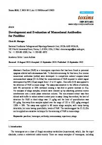
Figure 1.1: The Silsoe autonomous horticultural vehicle.
The new work presented in this thesis, started in 1996, extends the capability of the vehicle’s computer vision system, and has built on a considerable volume of previous effort invested in development of the vehicle [HT96, MB95, Mar96, PSM97, BM96, SPMB96, RWBM96, HMT97a]. The remainder of this section gives details of the autonomous vehicle and identifies the problems that the work presented later in this thesis aim to solve. For autonomous operation, the Silsoe vehicle requires two basic capabilities. The first is localisation, and the second is the ability to discriminate between the crop, weed and soil. Localisation with respect to some co-ordinate system is required if the vehicle is to navigate itself in a field of crop, and discrimination is necessary for the differential treatment of crop, weed and soil demanded by PSH. We shall treat the two capabilities separately below.
1.2.1 Localisation Hague and Tillett [HT96] presented the vehicle control and navigation architecture, an amended and simplified version of which is illustrated in figure 1.2. Many authors are concerned with estimating vehicle position relative to an absolute cartesian frame of reference [LDW91a, SSDW95, BDWH+ 90], but Hague and Tillet [HT96] argue that a more natural coordinate system for operation of the Silsoe autonomous vehicle is one that defines position relative to the rows of crop whose treatment is the focus of the PSH. The position estimator
1.2. The Silsoe autonomous vehicle project
22
in figure 1.2, which is a Kalman filter algorithm, calculates the distance that the vehicle has travelled along the row, the lateral position of the vehicle with respect to the central row of crop plants and the bearing angle of the vehicle with respect to the central row.
Path tracking control
demanded drive velocities
wheel velocity control
Motor drive signals Positional feedback
estimated position error
Position estimation
odometers accelerometers vision data
Figure 1.2: Vehicle control and navigation architecture.
Odometers and accelerometers are used to generate dead-reckoning estimates of the vehicle’s position, velocity and acceleration, with periodic drift correction to the lateral offset and bearing estimates provided by the computer vision system. The vision system designed by Marchant and Brivot [MB95], described in detail in appendix A, uses the Hough transform technique [Pra91] to fit a template of the crop row structure to the image, which yields the vehicle’s lateral offset and bearing relative to the rows. An input image and the fitted row model are pictured in figure 1.3. A small number of navigation trials performed by Hague et al [HMT97a] and Hague and Tillett [HT96], both in a test-bed environment and in a field of real crop, show that error in the estimate of lateral offset is of the order of 8 – 20
mm.
Forward position
estimates have not been assessed. The localisation system described above is used only when the vehicle is navigating along the crop row. At the end of a bed of crop, where a bed is three parallel rows as pictured in figure 1.3, the vehicle must turn and start following the neighbouring bed. The end of each bed is detected semi-automatically; the vehicle is given the approximate length of the bed and uses its estimate of forward motion, and the number of plant matter features detected by image processing to judge when the vehicle has reached the end of the bed. The vehicle then executes a pre-programmed turn under dead-reckoning control so that it is in approximately the correct position to travel along the next bed, the vision system starts up again and visually aided tracking re-commences [HMT97a].
1.2. The Silsoe autonomous vehicle project
23
Figure 1.3: The crop row structure. Left: a view of the field from the vehicle’s camera. Right: the crop rows as located by the Hough transform algorithm due to Marchant and Brivot [MB95].
1.2.2 Plant recognition In addition to localisation, a vehicle that performs PSH requires the capability to differentiate between crop plants and weed, so that treatment may be directed appropriately. To this end, Brivot and Marchant [BM96] propose candidate algorithms to separate crop, weed and soil pixels in monochrome images such as that seen in figure 1.3. The algorithms use a mixture of hysteresis thresholding of the pixel grey-levels, techniques from mathematical morphology and grey-level gradient information. Although they showed promise in off-line trials performed on a desk-top workstation with image sequences captured from the vehicle’s camera, the algorithms have proved unstable in on-line operation, and are sensitive to changes in illumination and also to the size of the crop plants and weeds [Mar99]. Sanchiz et al [SPMB96] and Reynard et al [RWBM96] present algorithms for tracking individual crop plants as the vehicle traverses the field. Both algorithms have been demonstrated off-line on sequences captured from the vehicle, but have not been implemented for on-line use. Sanchiz et al model each crop plant as a cluster of “blobs” extracted from the grey-level image by thresholding, and track the clusters to determine both the motion of the vehicle and the position of the plants with respect to the vehicle. The algorithm assumes that only image features that correspond to crop are given to the clustering algorithm, and relied on the method of Brivot and Marchant [BM96] to correctly provide these features. Reynard et al [RWBM96] model the crop plants using contour models [CB92] and demonstrate the robustness of their tracking algorithm to temporary occlusion, as may be caused by
1.2. The Silsoe autonomous vehicle project
24
shadows. No method of initialising contours to track particular plants was given, so again, the crop/weed discrimination problem was not solved.
1.2.3 The aims and contributions of this thesis The work presented in this thesis aims to extend the capability of the autonomous horticultural vehicle by introducing a vision algorithm that models the crop pattern as a grid of crop plants rather than a set of rows of plants. We aim to show that this seemingly small change leads to two principal advances: 1. Forward distance estimates may be obtained by a vision algorithm that tracks the crop grid model. In the original autonomous vehicle navigation system, estimates of forward distance are generated by dead-reckoning alone, and the row model used in the Hough transform vision algorithm does not permit estimation of forward motion. Deadreckoning systems are prone to accumulating errors that lead to biased position estimates, and problems with wheel-slip can lead to unreliable odometer measurements in the field. It is hoped that the addition of vision estimates of forward distance will correct for deadreckoning bias. 2. The crop grid model may be used as an aid for discriminating between crop and weed plants. For reasons we shall outline in chapter 2, discriminating between crop and weed plants with image processing techniques is a much harder problem than extracting both weed and crop features from the images. However, if we are successfully tracking the crop grid, then image features that support the estimate of grid position may be assumed to be crop plants, and the remainder weeds. The contributions made toward the autonomous vehicle project by this thesis are centred upon the development of an algorithm that tracks the crop grid model through image sequences using an extended Kalman filter. In addition to the advantages offered by a grid model over the row model, the use of the extended Kalman filter algorithm, described in detail in chapter 3, allows a more natural integration of the vision system with the vehicle’s position estimator than was achieved with Marchant and Brivot’s Hough transform algorithm. Furthermore, the Hough transform algorithm produces quantised estimates of vehicle position, whereas the Kalman filter tracker provides continuously valued output. In addition to the full development of two alternative grid tracking algorithms, a method for crop/weed discrimination is developed that clusters image features under the constraint that they support the crop grid model. The use of this algorithm leads to the segmentation of images
1.3. Thesis outline
25
into regions of crop, weed and soil. The classified image features may be used to guide the application of treatment. Each algorithm is implemented for off-line testing on a desk-top workstation, and performance judged on image data captured from the autonomous vehicle prior to implementation as part of the closed loop control of the autonomous vehicle. The off-line and on-line implementations differ for practical reasons, and these differences are discussed fully before both tracking and segmentation algorithms are demonstrated in the field with real crop. On a more theoretical note, we discuss the implications of the control theoretic concepts of observability and controllability for systems whose state is estimated by Kalman filters. A novel test for the observability of an extended Kalman filter is derived and the concept of “corruptibility” introduced, which is analogous to controllability for systems with stochastic inputs.
1.3 Thesis outline The development and testing of the tracking and segmentation algorithms is broken down into seven chapters. The first of these, chapter 2, introduces the crop grid model and discusses the perspective imaging of the crop through the vehicle’s camera. Two thresholding algorithms are proposed for extracting plant matter features from the image data, and their performance compared across a set of test images using receiver operating characteristic analysis, which also aids the selection of an operating point for the preferred thresholding algorithm. The recursive Kalman filter estimation algorithm, and the related extended Kalman filter, are discussed in chapter 3. We define and discuss the issues of controllability and observability and their implications for Kalman filtering. Corruptibility is defined, and a novel test for the observability of extended Kalman filters derived. The details of the extended Kalman filters implemented in this thesis are given in chapter 4. The process and observation models for the off-line implementations are given, and the transfer to the on-line system discussed. The filters are analysed in terms of their corruptibility and observability. The off-line tracking algorithms are demonstrated in chapter 5, together with initial navigation trials of the on-line system in a simplified indoor test-bed environment. In chapter 6, we address two practicalities that are important when using extended Kalman filters: initialisation and data association. The extended Kalman filter is a recursive algorithm where the latest estimate of the state of a process is a combination of the previous estimate and some measurements of the process of interest. The purpose of filter initialisation is to ‘bootstrap’ the recursion with an initial estimate of the vehicle’s location relative to the crop grid that will subsequently allow successful tracking. Data association techniques are required
1.3. Thesis outline
26
to extract appropriate features from the image data to use in estimating the crop grid position. Feature validation is also discussed. Whilst chapters 4 and 5 concentrated on the use of the crop grid model as a cue for navigation, chapter 7 shows how it can be used to classify image features as crop or weed. The algorithm is tested on image sequences captured from the vehicle at different stages of crop growth and in differing weather conditions. Two final experiments are presented in chapter 8, where the navigation and crop/weed discrimination algorithms are tested on a bed of real crop. Quantitative analysis of the online system’s navigation performance and spray treatment precision is given, and a qualitative analysis of crop/weed discrimination. We close with chapter 9, which reviews the results of our experiments and discusses their implications for plant scale husbandry. Directions for future work are identified.
Chapter 2
Image processing in the field environment In chapter 1, we introduced the Silsoe autonomous vehicle project as a test-bed for experiments in plant scale husbandry. The vehicle is equipped with a computer vision algorithm that uses a model of the rows of crop plants [MB95], in conjunction with a dead-reckoning estimator, to provide localisation information that allows the vehicle to navigate along the rows of crop plants in the field. In this thesis, we propose that using a crop grid model allows additional localisation information to be derived from the images (in the form of forward distance estimates) and also aids crop/weed discrimination. In this chapter, we review modelling techniques in computer vision to help us specify a model of the crop grid structure. The crop is viewed through a camera mounted on the front of the vehicle, and the perspective imaging of the scene is discussed, and formulae are presented which relate the ground plane position of the crop grid to the locations of crop plants in the image. We also discuss the processing of the images captured by the camera. To locate the crop grid model, it is necessary to extract the crop plant features from the image. In plant scale husbandry, we aim to treat weeds as well as (but in a different manner to) crop, so it is necessary to extract all plant matter from the image. Two grey-level thresholding algorithms are proposed for this purpose, and their performance on images collected from the vehicle is analysed using receiver operating characteristic curves. This method allows both overall performance comparison and a solution to the problem of operating point selection.
2.1 The semi-structured field environment As noted in chapter 1, the field environment in which the autonomous vehicle operates contains a natural “beacon” to navigate by in the form of the crop grid planting pattern. For agronomic reasons the crop, which in the examples given throughout this thesis is cauliflower, is planted in a grid structure which allows each individual plant space to grow and access to a region of soil
2.1. The semi-structured field environment
28
from which it draws nutrients. The standard practice is to grow seedlings in a greenhouse, and to transplant them into the soil at a later date. This planting process is performed mechanically by a transplanter, which places the seedlings on an approximately regular grid, a perspective view of which can be seen in figure 2.1. This approximate structure, imposed on the world by the crop planting can serve as a cue for the two aims of vehicle control: Navigation: the structure provided by the crop grid pattern may be used as a beacon to localise the vehicle relative to the crop. This localisation serves as an aid to the deadreckoning system for vehicle navigation. Treatment: the knowledge that crop plants are arranged in this grid structure may be used to discriminate between crop and weeds. Crop plants should lie within the grid structure where they were planted, whilst weeds will usually grow elsewhere, both because they tend to grow at random and because they will not thrive if germinating close to a well established seedling.
Figure 2.1: The grid planting pattern as captured from the vehicle camera.
The image in figure 2.1 has been taken from a sequence captured from the camera mounted on the vehicle. By using models of the grid structure and the motion of the vehicle, this grid structure will be tracked as the vehicle traverses the field. The following sections discuss object modelling in machine vision, whilst the problem of tracking receives attention in chapter 3.
2.1.1 Model based tracking in machine vision Model based tracking is a powerful method of reducing the computational load on an imageprocessing system. Rather than analysing all of a static image and categorising each object in it
2.1. The semi-structured field environment
29
separately, a model-based tracker aims to ‘lock on’ to a specific object or objects in an image sequence and use a priori knowledge of the appearance, and sometimes also the dynamics, of the object(s) to track it (them) throughout the sequence. Several different types of model have been proposed [Har92b, CTCG92, YCH89, Low90, BCZ93] with varying degrees of flexibility and rigidity, and it is important that an appropriate one is chosen, in order to capture the variability within the class of shapes modelled without introducing extraneous degrees of freedom. Subsequent sections review different modelling schemes that are popular in machine vision whilst bearing in mind that the task at hand is to model the grid structure of the crop planting pattern.
2.1.2 Active contour models A popular technique used in many tracking applications in machine vision is based upon the active contour model (ACM). Originally proposed by Kass et al [KWT87], the ACM, or “snake”, is a string of control points, coupled by an elastic material having tension and stiffness properties, which performs a local search in an image for features such as edges. In its original formulation, the snake is said to have converged when the “forces” caused by the internal stiffness and tension balance those derived from the edge features in the image. A drawback of the snake algorithm is that it requires a good initial configuration close to the required edge, otherwise it will simply relax to a straight line. The original tracking mechanism for the snake relied on small inter-frame motion. The predicted position of the snake in the next image of a sequence was simply the position at which the snake had converged in the current image. Later, more sophisticated predictive motion models were incorporated into the tracking mechanism [TS92, Bau96]. The idea of joining the ends of the contour to form a closed loop, or “balloon” with an added pressure force was then proposed [SWHB90, Coh91]. The pressure force makes the balloon expand until it meets a strong edge, so the initial position is no longer so critical. Also, owing to the internal smoothing forces, the balloon will ignore weak edges that may be caused by image noise. A further development of the balloon model is the statistical snake. This is an active region model (ARM) [IP94], which allows adaptive control of the pressure force to encourage the snake expand or contract in order to surround regions of an image conforming to a statistical model. This particular technique has been successfully applied to segmentation and tracking of road and track regions using statistical colour models [Ale98] and also to colour and texture segmentation [ZLY95]. The ACM incorporates a very simple shape model where the object of interest is a smoothly bounded region of the image enclosed by a perimeter of edge features. Such a model is sensitive to clutter in the image. A more robust tracker that is less sensitive to clutter could
2.1. The semi-structured field environment
30
be realised if the shape of the contour were further constrained to be specific to a particular class of objects. Curwen and Blake [CB92] describe such a method, where a B-spline ACM1 (or “dynamic contour”) is coupled to a template such that, in the absence of image forces, the contour’s shape is that of the template. This biases the contour to lock on to shapes in the image that are similar to the template. The models are permitted to deform under affine transformations, and a Kalman filter (see chapter 3) is used to track the contour position over time (similar motion models and tracking schemes have been proposed by Baumberg for more regular ACMs [Bau96]). This method was demonstrated to run in real-time on a small network of transputers. Since publication of the original work [BCZ93], the method has been developed extensively to incorporate features such as learning the dynamics of the object from training sequences [BIR94], and also differentiating between changes in object shape in the image that are caused by actual change of the object shape and apparent changes owing to object motion and change of viewpoint [RWBM96]. A further development is the CONDENSATION algorithm [IB96] used as the estimation mechanism in place of the Kalman filter. The strength of the CONDENSATION algorithm is that, unlike the Kalman filter which is restricted to the uni-modal Gaussian, it has the ability to handle multi-modal probability densities, thus enabling multiple hypotheses to be propagated through the tracking process. In particular, the capacity to maintain multiple hypotheses increases the robustness of the tracking process. For example, if the tracker becomes distracted by clutter in an image, a uni-modal tracker can fatally lose track because its single hypothesis allows only one object position to be represented. A multi-modal model, however, allows both the clutter positions and true object position to be represented, and when the clutter is found not to satisfy the dynamics of the model, then the true object mode will re-assert itself via propagation of the distribution through the state evolution model. Although active contour models have been used for tracking individual plants [RWBM96], and despite their success in many practical vision systems, active contour models and active region models are not natural candidates for the application at hand, which is tracking the position of the structure formed by a group of plants. When used to track the outline of an object, the ACM fits its control points to features (typically edge segments) and presents an interpolated outline of the object. The ACM method is not well suited to the crop grid tracking application of interest to this thesis, because the structure to be tracked is not a region or object enclosed by a boundary, but rather a set of individual crop plant positions.
1
This is essentially a B-spline where the control point positions are influenced by the image. Owing to the
implicit smoothness of the B-spline, the stiffness and tension forces of the Kass type snake are not required [BCZ93].
2.1. The semi-structured field environment
31
2.1.3 Point distribution models The point distribution model (PDM) [CTCG92] represents an object by the position of a set of, say n, landmark points derived from distinguishing features on its boundary or interior. The model is trained on several images, where landmarks have been specified by hand, which aim to represent typical variations in the object’s appearance. This is usually performed by aligning the training images using a Procrustes procedure [CTCG92] and carrying out a principal components analysis on the distribution of the aligned landmark points obtained from the training images. This determines the mean shape of the object together with vectors describing its statistically independent principal models of variation. Only the most significant modes are retained in the model and those accounting for little variation are ignored in order to limit the number of model parameters, thereby increasing efficiency and avoiding over-fitting problems. When coupled with an image feature search strategy, the PDM is known as an Active Shape Model (ASM). The feature search strategy is a method for fitting the model to a new instance of the object in an image. In fact, the original ASM paper [CT92] was subtitled “Smart Snakes”, highlighting the similarities between the ASM and ACMs discussed above, as both can be regarded as a collection of landmark or control points on an object whose positions are influenced by various “forces”. In an ACM, the control points are connected by elastic forces and there is no shape specificity. In the ASM formulation, the landmark point positions are coupled by the statistics underlying the PDM, which permits only certain modes of shape deformation. Since it allows the object shape to vary and since the variability may be learnt from example training data, active shape models have been used in the tracking of many types of biological objects, such as hands [Hea95], pigs [TOM97], fish [MT97] and flocks of ducks [SBT97]. With its ability to cope with deformations, the PDM/ASM is especially well suited to modelling the changes of shape caused by object flexibility, but it has also found application in fitting a generic model of an object to particular types. For example, Ferryman et al [FWSB95] construct a generic car model with basic features such as bonnet and boot of variable size and shape, and then train it on several different models of car, and use the resulting PDM in a system to lock on to and track any type of car present in the scene. Another option would be to use the PDM for the crop grid tracking problem with landmark points taken as the plant positions, but some care must be taken with the model construction. The Procrustes alignment procedure described by Cootes et al [CTCG92] uses a similarity transform (planar translation and rotation) to align the training shapes before the principal components analysis is performed. In our application, where we image the crop in perspective, a different transformation is required. Chatterjee and Buxton [CB98] use an affine transfor-
2.1. The semi-structured field environment
32
mation in the Procrustes alignment of examples of the outlines of drivable regions that have been extracted from images of unsurfaced country lanes. Although such an approach has not been taken in this thesis, it might be possible to use the perspective projection in an alignment scheme prior to computation of the mean of the aligned crop grid examples and computing their modes of variation in the usual manner. Chatterjee and Buxton also make the observation that the affine transformations between road surface and camera are not entirely random, because they are determined, by driver action, to keep the vehicle on the road. To capture this systematic variation they also performed PCA on the transformations [CB98].
2.1.4 Rigid models The planting pattern is an example of man-made structure imposed on the world. The tracking of man-made objects has been the focus of much attention [Ste89, Low90, Har92b]. Such objects are often rigid or have simple mechanical internal degrees of freedom and may usually be represented by CAD-like models. Stephens [Ste89] used a Hough transform method to track an object grasped by a robot arm. A full 3D model of the object was constructed, together with a look-up table to indicate which features (points on the object’s edges) should be seen from particular viewpoints. Although the pose estimates generated by the algorithm were noisy, the system was quite successful in dealing with occlusions and cluttered backgrounds. It should be noted that by its nature the resolution of any Hough transform pose estimator is limited by the quantisation of the Hough accumulator, and also that Stephens’ system had no means of capturing the dynamics of the model. The assumption was that there was little inter-frame motion and that the edge positions could be found in successive frames by local search from their previous locations. Lowe [Low90] extracted edge segments from the whole image and a non-linear minimisation procedure was used to fit a 3D model onto the image. In this case, both rigid objects and articulated objects with rigid subcomponents were modelled, although no quantitative analysis of the results was given. The RAPiD algorithm [Har92b] uses similar models to those of Stephens [Ste89] (points on object edges, with view graphs to predict occlusions for certain poses) to track aircraft and other objects. The tracking method employed here is the Kalman filter, and the algorithm produces high quality pose estimates in image sequences of both real and model objects. The Kalman filter yields continuous (i.e. unquantised) pose estimates, and also a measure of uncertainty on the estimate. Both the RAPiD algorithm and Stephens’ Hough transform method are designed for rigid objects of ideal shape. The crop grid pattern may be regarded as a rigid structure, because once the crop is planted it is fixed in position. However, the feature points (i.e. the crop plants)
2.2. Modelling and viewing the grid structure
33
should be allowed to occupy non-ideal positions owing to the variability in the planting process. Any model of the grid structure should allow for this uncertainty on individual plant positions, which leads us toward the flexible template model.
2.1.5 Flexible templates The flexible template [YCH89] is a relatively simple idea. A parameterised model of the object of interest is constructed, and the parameters are varied so as to fit the model to the image. Yuille et al [YCH89] introduced the deformable template and applied it to extracting features such as the eyes and mouth from images of human faces. Figure 2.2 illustrates their template for the eye. All of the labelled parameters are allowed to vary in a scheme which minimises a potential energy defined from the goodness of fit of the model to the image. The model of Xe Xc r a -P2
b
P1
c
b
Figure 2.2: A flexible template model of the human eye (adapted from Yuille et al [YCH89]).
the crop grid structure presented below bears similarities to both a rigid model and a flexible template, depending on whether or not its parameters are allowed to vary.
2.2 Modelling and viewing the grid structure The model of the crop grid pattern is depicted in figure 2.3, where the black circles represent the ground plane positions of the set of cauliflowers currently in the field of view of the camera. The figure also shows two sets of axes; (xw ; yw ) is the world co-ordinate frame with the world
z axis, zw , projecting into the page, and (xc; yc; zc ) are axes which belong to a co-ordinate system attached to the camera mounted on the vehicle, with zc describing the camera’s optic axis. Figure 2.4 shows an alternative view that clarifies the relationship between the two coordinate frames. The crop is assumed to lie on the ground plane zw
= 0, and the yw axis runs
through the central row of crop in the field of view. Errors arising from the assumption that the
2.2. Modelling and viewing the grid structure
34
crop lies in the ground plane are discussed in section 2.3.8 below. It should be noted that the world co-ordinate frames are local to the vehicle co-ordinate system, rather than being fixed to a particular origin in the world. Operations such as weed control and crop treatment are carried out by the vehicle, so it is sensible to describe the locations of the crop and weed in a co-ordinate system relative to the treatment system. As the vehicle moves across the field, the world axis xw axis moves in direct proportion to the distance travelled along the crop rows. A set of co-ordinates is marked on the diagram which specifies Row No. n -1
0
1
r -2 l Line No. m
-1
xw Y 0 zc xc tx yc
Ψ yw
Figure 2.3: The grid model. the position of the vehicle relative to the crop. These co-ordinates are tx , the offset of the optic axis from the central row of crop,
, the vehicle’s bearing relative to the central row of crop,
Y , which is the offset between the world xw axis and the bottom-most crop plant in the current image. Y is the co-ordinate which anchors the grid to the vehicle’s co-ordinate system. Two grid parameters, the mean inter-row spacing r� and inter-line spacing �l (figure 2.3) are used in conjunction with indices m and n to generate the world co-ordinates of the individual plants, and
as shown in equations 2.1 and 2.2.
xw = n � r�;
(2.1)
yw = m � �l + Y:
(2.2)
2.2. Modelling and viewing the grid structure
35
Marchant and Brivot [MB95] (appendix A) presented equation 2.1 in their work on using a Hough transform to track the row structure. As noted in chapter 1, their algorithm modelled the planting pattern as a set of rows only. In this thesis, the use of a grid model facilitates the identification of individual plants within the rows, as well as enabling the vision system to be used to estimate the forward position of the vehicle via Y . Estimates of the vehicle’s forward motion were not possible in the Hough transform approach. In chapter 4, two tracking algorithms are developed. The first estimates only the relative position of the crop to the vehicle, i.e. (tx ; Y and
).
In this case, the grid model is closely
related to the rigid models of Harris [Har92b]. In the second tracker, the grid parameters r� and
�l are also estimated.
In this case, the model is closer to the deformable template [YCH89],
although the fitting of
r� and �l is performed by an extended Kalman filter instead of via the
minimisation of a potential energy function.
2.2.1 Perspective imaging of the grid structure The crop grid structure is imaged by a monochrome CCD camera mounted on the front of the vehicle, with its optic axis pointing in the direction of motion at an angle � to the normal to the ground plane, as illustrated in figure 2.4. The images of the crop formed in this manner clearly show perspective effects as seen in figure 2.1 above.
xw
tz
φ
Y
yw
yc
zc
tz
zc xc
tx yc
yw
Ψ
Ground Plane zw
=Crop plant
Figure 2.4: The camera and world co-ordinate systems.
To model the imaging geometry, we begin with the perspective imaging equations of Tsai [Tsa86] and, following Marchant and Brivot [MB95] (appendix A), arrive at the following
2.3. Image processing
36
expressions for the 2D image plane co-ordinates (xu ; yu ) of ground plane features (xw ; yw ; 0):
(xw cos + yw sin + tx ) ; xu = f x sin w sin � , yw cos sin � + tz sin cos � + yw cos cos � + ty ) : yu = f (,xxwsin w sin � , yw cos sin � + tz
(2.3)
(2.4)
Equations 2.3 and 2.4 were derived by Marchant and Brivot [MB95] from those given by Tsai, with the added assumption that the camera does not pitch or roll (i.e that the camera axes
(xc ; yc ; zc ) of figure 2.3 do not rotate about the world axes xw or yw ). This assumption is made because the vehicle is running on well tended tilled fields, and it is confirmed from observation of several long image sequences. In equations 2.3 and 2.4, � is the angle between the camera’s
optic axis (zc ) and the world zw axis, whilst
is that shown in figures 2.3 and 2.4. f
is the
focal length of the camera’s lens. The quantity tz is distance along the optic axis between the camera’s optical centre and the point at which the optic axis intersects the ground plane. ty gives
the offset, in camera co-ordinates, of the point where the optical axis intersects the world xw axis and, as illustrated for our system in figure 2.4, may be set to zero. One further assumption is that the angle is small enough for the approximations
cos � 1 and sin � to hold.
This is typically the case when the vehicle is moving along the rows of crop. From the above, it is possible to generate image pixel co-ordinates
(xf ; yf ) for each plant
(m; n) by combining equations 2.1 and 2.2 with 2.3 and 2.4, and inserting a suitable estimate of the vehicle position (tx ; Y; ) and crop grid parameters r� and �l: f nr� + (m�l + Y ) + tx xf (tx; Y; ; r�; �l; m; n) = dx (2.5) nr� sin � , (m�l + Y ) sin � + tz + Cx ; f (m�l + Y , nr�) cos � yf (tx; Y; ; r�; �l; m; n) = dy (2.6) nr� sin � , (m�l + Y ) sin � + tz + Cy : centre
The values of dx and dy in equations 2.5 and 2.6 give, respectively, the horizontal and vertical dimensions of the camera pixels, whilst
(Cx ; Cy ) is the co-ordinate (in pixels) of the centre
of the imaging surface. It should be noted that equations 2.5 and 2.6 do not correct for lens distortion. Tsai’s original model and camera calibration algorithm do allow for radial lens distortions, but previous work from the autonomous vehicle project has suggested it is not necessary to include such factors here [Mar96].
2.3 Image processing Given the crop grid structure and imaging geometry, the expected image position of crop plants can be generated using equations 2.5 and 2.6 as described in the previous section. Image processing is then used to provide plant features to which the crop grid model may be fitted.
2.3. Image processing
37
Ideally, we would be able to extract the crop plants and weeds separately, and fit the crop grid model to the crop plant features alone. However, even plants of the same species and age may have different numbers of leaves or different sized leaves which can overlap in different ways, so there is a great deal of variability within a species. It would be difficult to build a model that could capture such variability without over-generalising to other species. An option might be to model an individual crop plant leaf and locate all of the leaves in the image. Nielsen et al [Nie94] and Abbasi et al [AMK97] both present schemes for recognising leaf outlines, either using point distribution models [Nie94] or a curvature scale-space representation [AMK97]. However, both of these systems rely on the leaves being imaged one at a time when they are laid flat. In the field, the leaves are three-dimensional objects that will most likely be partially occluded, and neither system addresses these issues. An active region model [IP94] (section 2.1.2 above) driven by a colour or texture model would be a useful solution for extracting one species of plant, provided that a suitable colour or texture model could be found. Zwiggelaar [Zwi98] conducted a survey of research using spectral techniques for plant species recognition with a view to their potential use in crop/weed discrimination. The conclusions of this review were that red and near infra-red wavelengths were most effective for species identification, but that a classifier based on spectral information alone was unlikely to prove robust. As we shall see below, spectral information is useful for differentiating between plant matter and soil, but it would appear that it is not the solution for crop/weed discrimination. Unfortunately texture modelling is not viable either. As visual inspection of figure 2.7 will confirm, our current imaging system does not have sufficient resolution to allow textural differences between crop and weed plants to be discerned. However, Soille [Soi99] has used morphological operators on higher resolution non-perspective colour images to extract cauliflowers with some success. The algorithm uses the distinctive vein structure found in the cauliflower leaves as a cue for segmentation, but this is not visible in the near infra-red perspective images captured from the vehicle. One cue that we can use, however, is scale. The weeds are typically smaller than the crop plants, and we will exploit this property in the crop/weed discrimination algorithm described in detail in chapter 7. Until we are able to model the plants more effectively, we aim to extract features describing both crop and weed from the images and use the data association techniques discussed in chapter 6 to select the features used for fitting the crop grid model. Our image processing algorithm for plant feature extraction comprises two stages. The first stage aims to extract crop and weed plant matter pixels from the image – this is performed by a
2.3. Image processing
38
grey-level threshold algorithm described below. The second stage is feature extraction. Pixels classified as plant matter are grouped into “blobs” in the image (a blob being a set of connected neighbouring pixels), and the centroid and size of these blobs are used to characterise them as crop plant or weed. The crop/weed classification process is detailed in chapter 7. Sections 2.3.1 – 2.3.6 present the thresholding algorithm and methods for performance evaluation and parameter setting of this algorithm. Feature extraction, and potential problems with the feature extraction process are then discussed (sections 2.3.7 and 2.3.8).
2.3.1 Thresholding IR images Biller [Bil98] has noted that contrast between soil and plant matter in monochrome images captured in the near infra red spectrum is greater than contrast in monochrome images taken in the visible spectrum. The reason for this is illustrated in figure 2.5, which shows the reflectance spectrum for a plant of the brassica family (of which cauliflower is a member) together with the reflectance of soil. The brassica data comes from the LOPEX data set [HJA+ 95], whilst the soil spectrum is modelled as a straight line using data from Biller [Bil98]. No reflectance data is available for the weed population, but the brassica data has characteristics typical of most plant species. In the visible spectrum (c. 400 – 700 nm), the reflectance of plant matter and soil are quite similar, soil being more reflective on the whole than the crop. However, in the near infra-red section of the spectrum (particularly in the 760 – 850
nm region), the
reflectance of the plant matter is much higher than that of the soil2 . This will lead to strong contrast between plant matter and soil in well illuminated images captured at these wavelengths (a typical monochrome CCD camera is sensitive to wavelengths of up to 1100
nm).
For this
reason, a filter is placed over the vehicle’s camera which blocks visible light and passes infra-red alone. The enhanced contrast makes the use of a grey-level threshold a viable plant matter/soil discrimination technique on the near infra red images thus formed. We now aim to demonstrate the effectiveness of thresholding on example images captured in the field at different stages of plant growth and under different weather conditions by using receiver operating characteristic curves to analyse the results of thresholding.
2.3.2 Evaluation of the segmentation algorithm To assess the utility of grey-level thresholding for classification of these images into plant matter and soil regions, and also to aid the choice of a suitable threshold level, receiver operator characteristic (ROC) curves [GS66, vT68] are used. The discriminatory power of a classification algorithm controlled by a single parameter is reflected by the area under the ROC curve, and 2
Unfortunately, consistent separation of crop and weed plant species using spectral reflectance is not achievable
[Zwi98].
2.3. Image processing
39
55 50 45
Degree of reflection (%)
40 35 30 25 20 15 10 5 400
brassica soil 500
600 700 Wavelength of ambient light (nm)
800
900
Figure 2.5: Reflectance of plant matter and soil. Solid line – reflectance of brassica plant material. Dashed line – soil reflectance.
the operating point for the controlling parameter may be selected using the slope of the ROC curve. The use of the area under an ROC curve is described below, whilst parameter selection is discussed further in section 2.3.6. The reflectance characteristics shown in figure 2.5 would indicate that plant matter should be considerably brighter than the soil under the infra-red illumination present in natural sunlight. In the image, the grey-levels of the plant matter pixels should thus be higher than those of the soil pixels. If this is so, then grey-level should be a useful discriminant between the two populations. A rank order statistic, known as the Wilcoxon statistic (sometimes known as the Mann-Whitney statistic) [vdW69] tests the null hypothesis that a variable is not useful for discriminating between samples from two populations. If this hypothesis is not proven, then the variable is a useful discriminant. The Wilcoxon statistic is described here because it has been shown to be equivalent to the area underneath an ROC curve [HM82]. The equivalence arises from the fact that both quantities measure the probability that in randomly paired soil and plant matter pixels, the grey-levels will allow the two pixels to be correctly identified. In subsequent sections, image pixels are separated into two classes; plant matter composed of both crop and weed, and soil. In the language of two class discrimination problems, the plant matter pixels are considered to be “positives” and the soil pixels to be “negatives”. Both classes may be characterised by a parameter
g (in our case the pixel grey-level).
If we denote the
2.3. Image processing
40
parameter value of a negative case by gN and the parameter value of a positive case by gP , over the population of positives and negatives it is traditionally stated that
gP > gN ;
(2.7)
i.e. that gP is “stochastically larger” than gN . This is assumed in the following discussion. In
the Mann-Whitney test, the null hypothesis is that the values gP are not statistically higher than
the values gN , i.e. that
Pr(gP > gN ) = 0:5;
(2.8)
Pr(�) denotes probability. This is the probability that is estimated by the Wilcoxon statistic. If g is a suitable discriminant, then this probability will be much closer to one than to
where
0.53 . In the case of discrete data (such as pixel grey-levels), Hanley and McNeil [HM82] showed that the Wilcoxon statistic may be computed from a set of comparison scores. Compare each pair of pixels gP and gN , and score the comparison as follows
8 > > 1 if > < S (gP ; gN ) = > 21 if > > :
0
if
gP > gN gP = gN : gP < gN
(2.9)
To compute the Wilcoxon statistic for a set of nP positive examples and nN negatives, the following formula is used:
1
nP X nN X
S (gP ; gN ): W = n �n P N 1 1
(2.10)
For two populations that are completely separable by parameter g , this statistic will have the value 1; if they are completely overlapping, then the null hypothesis that discriminant is true, and the value of W is 0.5. The closer
g is not a useful
W lies to 1, the better the two data
sets may be separated using the parameter g as a discriminant.
Hanley and McNeil [HM82] demonstrate the equivalence between the Wilcoxon statistic and the area under the ROC curve. Thus, the area under the ROC curve will indicate whether the parameter
g is suitable for distinguishing between two data sets.
Given the area under an
ROC curve � , it is stated that
� = W = Pr(gP > gN ):
(2.11)
The formation of the ROC curve for the binary classification of images is now discussed. 3
If the probability is close to zero, then the two data sets are distinct, but gP
< gN .
2.3. Image processing
41
If a pixel classification algorithm uses a single threshold
�
to control its performance,
then an ROC curve is produced by varying this threshold or decision parameter and analysing the performance of the algorithm at each operating point. To analyse the performance, a set of test images is required for which there is a ground truth classification, with every pixel labelled either positive or negative4 . These test images are used for comparison with automatic classification results. A number of settings of the threshold
�
are chosen and the algorithm
applied to a test image. At each setting, it is possible to place every pixel into one of four groups: 1. True Positives (TP): plant matter pixels correctly classified as plant matter. 2. False Positives (FP): soil pixels incorrectly classified as plant matter. 3. True Negatives (TN): soil pixels correctly classified as soil. 4. False Negatives (FN): plant matter pixels incorrectly classified as soil. From these four classes, two figures can be derived; the true positive ratio TPR =
number of TP ; number of TP + number of FN
(2.12)
FPR =
number of FP : number of FP + number of TN
(2.13)
and the false positive ratio
The TPR gives the probability that a positive (plant pixel) will be correctly classified at a threshold setting, whilst the FPR is the probability that a negative (soil pixel) will be incorrectly classified at the same setting. Because they are probabilities, TPR and FPR both lie in the range
(0; 1).
For each setting of the threshold � , a (TPR,FPR) pair is generated which are plotted against
each other to form the receiver operator characteristic (ROC) curve. We can similarly produce an ROC curve for an entire image test set by calculating TPR and FPR on the basis of classified pixels from each image in the set. Owing to the range of TPR and FPR, the curve is bounded by the unit square (the ROC space), and it is also always possible to find parameter settings that generate the extreme points (0,0) and (1,1), where every pixel is classified as negative or positive respectively. The area under the ROC curve is denoted
� and, as stated in equation
2.11, is equivalent to the Wilcoxon statistic [HM82]. 4
In practice, it may be wise to exclude certain pixels from the ground truth classification; this is discussed further
in section 2.3.4.
2.3. Image processing Whilst the Wilcoxon statistic
42
W tests the separability of two data sets using a parameter
g, the area � underneath an ROC curve generated over a range of algorithm parameter settings � reflects the ability of the algorithm to separate the data. An algorithm with the worst possible classification performance produces an ROC curve with area � = 0:5. Such an algorithm randomly classifies each pixel as positive or negative with equal probability regardless of the true class of the pixel. When
� = 1.0, the algorithm is perfect, and the two sets are classified
without error. ROC curves for these two extreme cases are illustrated in figure 2.6. The ROC curve for the perfect classifier runs along the TPR axis from (0,0) to (0,1) and then between the points (0,1) to (1,1), whilst the line running along the (0,0) – (1,1) diagonal is the ROC curve for the classifier which does no better than random chance. For this reason, the (0,0) – (1,1) line is often known as the “chance diagonal”. 1
0.8
TPR
0.6
0.4
0.2 random chance ideal 0 0
0.2
0.4
0.6
0.8
1
FPR
Figure 2.6: The ideal and random chance ROC curves.
If we have two (or more) rival algorithms designed to perform the same segmentation task, then the area � is a suitable metric to aid the selection of one of these algorithms. The algorithm which produces the ROC curve that encloses the greatest area will provide the best overall classification performance for a range of threshold or decision parameter settings.
2.3.3 Image sequences and ground truth Throughout this thesis, four sequences of images captured from the vehicle are used for offline testing of classification algorithms. An example image from each sequence is given in figure 2.7 (a)–(d). The sequences have been chosen to represent a range of crop growth stages and imaging conditions, although this range should by no means be considered exhaustive. Sequence A consists of 960 images of crop that is approximately 8 weeks old, with few weeds,
2.3. Image processing
43
recorded on an overcast day, sequence B has 960 images of 3 week old plants in overcast conditions with very few weeds present, sequence C contains 1380 images of 6 week old crop with a moderate weed density, and sequence D (1280 images) is again of 3 week old crop with few weeds, but this time in bright sunlight. The resulting shadows can be seen clearly in D. To
A
B
C
D
Figure 2.7: Examples from the four image sequences A – D.
test the effectiveness of thresholding these images, a subset of each image sequence was chosen such that no two images are of overlapping areas, which ensures that no two pixels in the test set represent the same patch of soil or plant. For each image in these test sets, a ground truth labelling was produced by hand segmenting the image pixels into three classes: crop, weed and soil. The ground truth images can then be used for comparison with the output of the automatic classification algorithms. The crop and weed ground truth images are combined to provide a plant matter labelling or “mask” image, used in the evaluation of the thresholding algorithms presented below. An example image from sequence C and its plant matter mask can be seen in figure 2.8, where the soil is black and plant matter is white. As can be seen from the mask
2.3. Image processing
44
Figure 2.8: An image and its plant matter mask.
image in figure 2.8, only the plants in a trapezoidal area of the image have been segmented by hand. This is because the segmentation algorithm described in chapter 7 operates only on those features that lie within the area between the wheels of the vehicle. This is the region that undergoes treatment from the vehicle’s spray bar, and it is determined by using knowledge of the vehicle’s dimensions and position relative to the crop.
2.3.4 Segmentation experiments – algorithms and measurements Two algorithms have been tested for the segmentation of plant matter from soil on the basis of infra-red image grey-level value. The first algorithm is a straightforward threshold on the grey-level, where the value of the output pixel O (xf ; yf ) is given by
8 < 255 if O(xf ; yf ) = : 0 if
I (xf ; yf ) � � ; I (xf ; yf ) < �
(2.14)
where I (xf ; yf ) is the corresponding pixel from the input image and � is the threshold setting that is varied to produce points on the ROC curve. According to equation 2.14, bright pixels above or equal to the threshold � are labelled white, as plant matter, whilst the duller pixels are labelled black, as soil. The second algorithm, proposed by Hague [Hag98], is based on the observation that there appears to be a brightness gradient across the ground plane in many of the example image sequences. The cause of such a gradient is most likely the position of the Sun relative to the ground plane and the vehicle’s camera, and the interaction of the illuminant with the rough surface of the soil. Accurate modelling of illumination and reflectance effects is a complex issue and not of concern in this thesis. More complex models are known for surface reflectance, such as those due to van Branniken et al [vBSK98] or Oren and Nayar [ON95].
2.3. Image processing
45
The thresholding algorithm proposed by Hague uses a linear approximation of this gradient as a function of the yf (i.e. vertical pixel co-ordinate) position of each pixel in the image. The algorithm is also adaptive to the average brightness of the image, which will offer some robustness to changes in illumination as, for example, when the Sun is temporarily masked by a cloud. A mean grey-level is computed for both the top (�1 ) and bottom (�2 ) halves of the image and these two means are used as fixed points to linearly interpolate a mean �(yf ) across
the height of the image. The value of the output pixel
O(xf ; yf ) is now given by the adaptive
interpolating thresholding algorithm:
8 < 255 if O(xf ; yf ) = : 0 if
I (xf ; yf ) � ��(yf ) ; (2.15) I (xf ; yf ) < ��(yf ) where � is a gain that is used to set the threshold level. � is varied to produce points on the ROC curve. As will be demonstrated by the results below, this simple algorithm offers an improvement on the straightforward fixed threshold of equation 2.14. Before we present the results and comparison of the two thresholding algorithms, a comment on the ground truth images used is required. The ground truth images are produced by hand using standard image-editing software, and are subject to error, especially at border pixels where plant matter is adjacent to soil. Some of these pixels will be soil misclassified by hand as plant matter, some plant matter pixels will be misclassified as soil, and some pixels will genuinely be of mixed class. Alexander [Ale98] noted such problems with border pixels and proposed that at the border between foreground (in our case plant matter) and background (soil), regions of doubt should be inserted, and the pixels within these doubt regions should be ignored for the purpose of assessing classifiers. This strategy is followed here. All pixels that are on the border of plant matter and soil in the ground truth images are assigned to the doubt class and ignored in the classification assessments. To demonstrate the effect of including and excluding the doubt regions on classification performance, figure 2.9 shows three ROC curves for the performance of the threshold described by equation 2.14 when applied to image sequence C. The solid line plots the ROC curve that results when the border pixels are excluded from the classification, the dashed line shows the ROC curve obtained when the border pixels are included as soil, and the dotted line plots the ROC curve when border pixels are included as plant matter. The area under the curve is greatest when the doubt pixels are excluded from classification: 0.9846, compared with 0.9790 when border pixels are classified as soil, or 0.9842 when they are classified as crop matter. Since this effect is caused by uncertainty in the ground truth classification, such border pixels should be ignored when assessing algorithm performance.
2.3. Image processing
46
1
0.8
TPR
0.6
0.4
0.2 Ignoring border pixels Border pixels are soil Border pixels are plant matter 0 0
0.2
0.4
0.6
0.8
1
FPR
Figure 2.9: The effect of border pixels on classifier performance.
2.3.5 Segmentation experiments – results Figure 2.10 shows the ROC curves generated for the fixed threshold algorithm (dashed), and the adaptive interpolating threshold algorithm (solid) on each of the four data sets. Each curve was generated using 27 parameter settings; 27 settings of the threshold
�
(equation 2.14) for
the fixed threshold algorithm, 27 settings of the gain � for the adaptive interpolating threshold algorithm (equation 2.15). The area under each ROC curve calculated using the trapezium rule is given in table 2.1. Alexander [Ale98] has demonstrated empirically that the area underneath an ROC curve calculated by this method is insensitive to the set of thresholds (or gains) chosen to generate the curve. Different choices of thresholds were found to lead to variation in area only in the 6th decimal place. A more principled analysis of the standard error of the area under the ROC curve is presented by Hanley and McNeil [HM82]. However, for this calculation to be computationally tractable on data sets of the size under consideration here (millions of pixels), knowledge of the underlying probability distributions of the positive and negative classes is required. For this reason, the areas are presented to the 4th decimal place, reflecting the level of confidence used by Alexander [Ale98]. Inspection of the figures in table 2.1 and of the curves in figure 2.10 shows that for sequences A–C the performances of the fixed threshold algorithm and the adaptive interpolating threshold algorithm are very similar. The adaptive threshold algorithm performs marginally better than the fixed threshold algorithm for sequences B and C, whilst the fixed threshold is very slightly superior for sequence A. The adaptive interpolating threshold is noticeably better with
1
1
0.95
0.95
0.9
0.9
TPR
TPR
2.3. Image processing
0.85
0.8
47
0.85
0.8
0.75
0.75 Adaptive Fixed
Adaptive Fixed
0.7
0.7 0
0.05
0.1
0.15
0.2
0.25
0.3
0
0.2
0.4
0.6
FPR
0.8
1
FPR
A
B
1
1
0.95 0.8
0.9
TPR
TPR
0.6 0.85
0.4 0.8
0.2 0.75 Adaptive Fixed
Adaptive Fixed
0.7
0 0
0.2
0.4
0.6
0.8
1
0
0.2
0.4
FPR
0.6
0.8
1
FPR
C
D
Figure 2.10: Experimental results, data sets A–D. Solid line – adaptive interpolating threshold. Dashed line – fixed threshold. Note the changes of scale between plots. Data Set
Fixed
Adaptive
A
0.9958
0.9957
B
0.9749
0.9779
C
0.9816
0.9846
D
0.8835
0.9241
Table 2.1: Area underneath ROC curves for the fixed threshold and adaptive interpolating threshold algorithms for data sets A–D.
2.3. Image processing
48
an area of 0.9241 vs. 0.8835 for the fixed threshold for sequence D. Interpolation across the height of the image would appear to compensate for the shadows present in sequence D (figure 2.7 D shows an example), even though the shadow only extends across the bottom quarter of the image. For this reason, the adaptive interpolating threshold algorithm is selected for image processing in preference to the fixed threshold.
2.3.6 Threshold gain selection The area under an ROC curve offers a measure of the effectiveness of an algorithm over a range of operating points. The slope of the ROC curve may be used to select the operating point of the algorithm (in our case, the threshold gain �). The “best” operating point is the one which minimises the Bayes risk attached to a decision. Bayes risk combines the probabilities of correct and incorrect decisions together with the costs incurred by making an error and the values associated with proper classification. van Trees [vT68] gives the following formula for the Bayes risk associated with a decision strategy,
R = CFPPNPr(FP) , VTNPNPr(TN) + CFNPPPr(FN) , VTP PPPr(TP);
(2.16)
Cresult is the cost of a particular incorrect decision, Vresult the value of particular correct decision. Pclass is the prior probability of a positive (P) or negative (N) case occurring (PP + PN = 1), and Pr(result) is the probability that the outcome of the thresholding decision
where
will be FN, FP, TN or TP. In fact, these probabilities are provided by
Pr(TN) = 1 , FPR;
(2.17)
Pr(FP) = FPR;
(2.18)
Pr(TP) = TPR;
(2.19)
Pr(FN) = 1 , TPR;
(2.20)
and
where TPR and FPR are given by equations 2.12 and 2.13. If we now substitute the four expressions above into equation 2.16, and differentiate it with respect to the threshold gain �, the following expression is obtained
@ R = P (C + V ) @ FPR , P (C + V ) @ TPR : N FP TN @� P FN TP @� @�
(2.21)
Equation 2.21 describes how the Bayes risk R changes with variation of the threshold gain �. The risk is at a minimum when this expression is set to zero, which occurs when the slope of the ROC curve, @TPR=@FPR, is given by
@TPR = PN(CFP + VTN ) : @FPR PP(CFN + VTP )
(2.22)
2.3. Image processing
49
Thus, the best operating point of a classifier is the threshold gain at the point on the ROC curve where the slope is given by equation 2.22. This result requires that the prior probabilities
PP
and PN of the occurrence of the positive and negative classes respectively are known, and also that the values and costs of correct and incorrect decisions are available. These values and costs are application specific and will ideally be set by a domain expert. The adaptive interpolating threshold algorithm has a gain parameter, �, that was varied to create the points on the ROC curves plotted in figure 2.10. For each sequence a value of this gain may be chosen using the gradient methods outlined in section 2.3.2, provided that prior probabilities for the occurrence of soil and plant pixels are known together with the costs and values of incorrect and correct decisions. The prior probabilities of the different types of pixel occurring may be obtained from analysis of the ground truth images (once again, the doubt category pixels are excluded), but no such simple prescription exists for assessment of the costs and values, which must be set according to the requirements of the task. In fact, if we look back at equation 2.22, which sets the slope for optimal performance, it can be seen that the individual costs and values are not necessarily required to set the operating point, provided that the “costs ratio”
CFP + VTN = @ TPR PP ; �= C FN + VTP @ FPR PN
(2.23)
is known. If the costs ratio is greater than 1, then the emphasis is on the correct classification of negatives; if the costs ratio is less than one the emphasis is on the correct classification on positives. In our case, navigation requires that the image processing provides features that support the crop grid model of figure 2.3. It should extract image features that accurately represent the crop plants with few false positive (i.e. misclassified soil pixels), especially at the edges of the plants. Equation 2.23 can be used to set the value of
�.
The parameter
� was tuned by hand
on images from sequence C5 , and the slope of the ROC curve for the adaptive interpolating threshold algorithm on sequence C was found (several values of � around the tuned point were used to generate a dense sampling of the ROC curve, and the slope was calculated by central
� derived as described above by hand is 1.64, corresponding to a costs ratio � of 3:644. The values of � set with � = 3:644 for each sequence are given in table
differences). The value of
2.2 below, together with the TPR and FPR associated with the given threshold gain. In table 2.2, where the costs ratio is set at
3:644, it can be seen that for sequences A–C,
over 80% of plant matter pixels are correctly identified (TPR), with less than 0.5% soil pixels 5
The parameter
� was set such that the plant matter in the image was well represented in the resulting binary
image, whilst keeping down the number of incorrectly classified soil pixels.
2.3. Image processing
50
Sequence
�
TPR
FPR
A
1.32
0.95623
0.00311
B
1.73
0.82434
0.00073
C
1.64
0.83421
0.00409
D
2.91
0.28627
0.00135
Table 2.2: Threshold gains � for each image sequence. misclassified (FPR). Although a correct classification rate for plant pixels of 80% may seem low, perusal of figures 2.11 – 2.13, where an example segmented image from each image sequence is presented along side its ground truth plant matter image, shows that most of the plants are well represented in the automatically segmented image. For sequence D, only 28.6% of plant
Figure 2.11: Example segmentation for sequence A. Left: ground truth. Right: automatic segmentation.
Figure 2.12: Example segmentation for sequence B. Left: ground truth. Right: automatic segmentation.
pixels are correctly classified, although the misclassification rate of soil pixels is only 0.135%. The example segmented image and its ground truth plant matter image can be seen in figure 2.14 where, as might be expected from the TPR and FPR figures in table 2.2, many of the plant
2.3. Image processing
51
Figure 2.13: Example segmentation for sequence C. Left: ground truth. Right: automatic segmentation.
Figure 2.14: Example segmentation for sequence D. Left: ground truth. Right: automatic segmentation.
2.3. Image processing
52
matter pixels are missed, and there are also very few misclassified soil pixels. The costs ratio was set for sequence C such that the crop plant pixels were well represented in the segmented images; in the absence of strong shadows, this costs ratio would seem suitable, as the results for sequences A and B bear out. If the performance of the segmentation algorithm were invariant to the effects of shadows, the costs ratio would ensure similar performance on sequence D. However, the figures in table 2.2 and the example image of figure 2.14 illustrate that the algorithm performance is not invariant to shadows, and the costs ratio set on sequence C leads to many plant pixels being misclassified. By setting � = 2:15, more plant matter pixels are correctly classified whilst keeping the number of misclassified soil pixels under 2%. The costs ratio corresponding to this operating point is 0.322; the TPR and FPR figures are given in table 2.3, and an example segmentation in figure 2.15. Sequence
�
TPR
FPR
D
2.15
0.599396
0.017743
Table 2.3: Threshold gain, TPR and FPR for sequence D with new costs ratio.
Figure 2.15: Example segmentation for sequence D with revised cost ratio. Left: manual ground truth image. Right: automatically segmented image.
Before moving on to how we extract features from the plant matter images, a comment on the cost ratios for sequences A – C and D should be made. In sequences A – C, the costs ratio is 3.644, so the emphasis is on the correct classification of soil pixels; in these evenly illuminated images the plant matter pixels are easily distinguished, so the challenge for the classifier is to reduce the number of soil pixels classified as plant matter. For sequence D, the ratio drops to 0.322, which places an emphasis on the correct classification on plant pixels. The bright sunlight present throughout sequence D results in deep shadows cast by the vehicle, and also specular highlights on the soil; the result of these effects is that it is harder to extract plant
2.3. Image processing
53
matter from the images, so the classifier is required to weight correct classification of plant matter more.
2.3.7 Feature extraction The thresholding algorithm described above takes images as input, and produces images (albeit simple ones) as output. Figures 2.11 – 2.15 show typical thresholded images, where, ideally, every white pixel is plant matter, and every black pixel soil. The pixels are clustered into “blobs” in the image, and each of these blobs will be interpreted as either a crop plant or a weed by the algorithms presented later in chapter 7. These algorithms classify the blobs on the basis of their position on the ground plane relative to the crop grid, and their size. The position of each blob is found by locating its centroid in the image and projecting this on to the ground plane via the camera calibration. The size of a blob is calculated by counting the number of pixels in that blob. The feature extraction process takes the binary images, clusters the pixels into blobs and produces a list of centroids and areas describing those blobs. We have chosen to use the chaincoding algorithm due to Freeman [Fre61] to perform these actions. Alternatives such as region growing or split and merge algorithms [Pra91] would give the same results on such simple binary images.
Figure 2.16: An image, its automatically extracted plant matter and the contours extracted by chain-coding the image.
The operation of the chain-coder is sketched in figure 2.16. The original image is seen on the left, with the thresholded binary image in the centre. The image on the right of figure 2.16 shows the blob contours extracted by the chain-coding algorithm. The centroid and size of each blob is easily computed from the outline.
2.3.8 Problems with feature extraction The feature extraction techniques described above are simple and fast, and therein lies their appeal for a real-time application such as vehicle navigation. The simple nature of the algorithms
2.3. Image processing
54
mean that some types of error are likely to occur. Pixels of different classes (representing crop, weed or soil) may become clustered into a single blob – each blob is interpreted, and classified, as a single type of plant, so some of these pixels will be misclassified. Furthermore, the centroid of a blob containing a mixture of pixels will not necessarily correspond to the centre of a plant, nor will the blob’s size in pixels reflect the size of a plant. The centre of the plant is taken to be the root of the plant for navigation purposes, as the root gives the grid position in which the cauliflower was originally planted. Other errors caused by the use of a simple threshold are illustrated below, together with a note on the interpretation of the blob centroids as points in 3D space. The experimental results of chapters 5, 7 and 8 demonstrate that the algorithms developed later in this thesis for vehicle navigation and image segmentation show considerable robustness to these errors in many circumstances. The centroid of the blob features is interpreted by the tracking algorithm as the position of the plant’s centre on the ground plane. Obviously, when a blob consists of a mixture of pixels from different classes, the centroid is not the centre of an individual plant. Notably, when the crop plants grow above a certain size, they start to touch in the image, which will lead to them being merged during feature extraction. An example of this from sequence A is illustrated in figure 2.17, where four plants merge into a single outline, and are therefore represented by a single centroid and area. This aspect of the feature extraction obviously limits the operating range of the autonomous vehicle. If a sizeable proportion of plants start to touch in the image, the features extracted from the image no longer relate to the crop plant centres required by the crop grid tracker. At this stage, the vehicle will be unable to track the grid, so navigation and segmentation will not be possible. This situation is one of the more compelling reasons for finding a more sophisticated image processing technique that will allow the extraction of plant centroids directly from the grey-level image data. The opposite of the merging of several plants can also occur. A single plant may become fractured into several disparate features. If there is a dark region (such as a shadow) between the main part of a plant and one of its leaves, then this leaf will be fractured from the plant body by the thresholding algorithm, and will generate a separate feature. An image detail from sequence C where this occurs is presented in figure 2.18. Chapter 7 contains an algorithm for clustering split features into single plants. One further problem pertains to the interpretation of the blob centroids in terms of their 3D position. The centroids are translated from screen to world co-ordinates using the camera calibration, together with the assumption that they lie on the ground plane, i.e. have zw
= 0.
In fact, the plants are complex three-dimensional objects, and the centroid of each image blob
2.3. Image processing
55
Figure 2.17: Large plants merge into a single feature. Left: image detail. Middle: thresholded detail. Right: feature outline.
Figure 2.18: A plant fractures upon thresholding. Left: image detail. Middle: thresholded detail. Right: feature outlines.
2.3. Image processing
56
represents a point in 3D space above the ground plane. When these true 3D positions are interpreted as ground plane positions, a projection error will occur. Unless the shape of the plants is known, it is impossible to exactly quantify the magnitude of these projection errors. An estimate of the errors may be obtained, however, by modelling the crop as a simple shape, such as an inverted hemisphere (to mimic the spreading of the cauliflower’s leaves), then rendering a scene of these hemispheres as if viewed through the vehicle’s camera. Results from such a test with hemisphere radius 150mm yielded a maximum error on the yw co-ordinate of 178:0mm (minimum 44:3mm), and on xw co-ordinate of 53:2mm (minimum 0mm, along the camera’s optic axis). To reduce the magnitude of these errors, we construct a “virtual ground plane” above the soil and project the feature centroids onto this, as illustrated with inverted hemispheres in figure 2.19. By setting the height of the virtual ground plane equal to that of the hemispheres, the projection errors drop to a maximum magnitude of 90:8mm in the yw direction (minimum
50:0mm) and 23:0mm maximum error in the xw direction (minimum 0:0mm, again along the
optic axis). For smaller plants such as the weeds which lie closer to the ground plane than the crop, projection onto the virtual ground plane will increase the feature localisation error. However, this is acceptable for navigation because it is the crop plants whose position directly affects the estimate of crop grid location. For precise treatment of weeds, however, the use of the virtual ground plane may be undesirable, because of the enlarged projection errors for plants closer to the true ground plane.
2.3.9 Image processing – summary This section has covered the image processing algorithms used to extract features describing plant matter from the images captured by the autonomous vehicle. Two alternative thresholding algorithms have been tested, a fixed threshold algorithm and an adaptive interpolating threshold algorithm, and their performance compared using the area under ROC curves. Operating points have been set using the slope of the ROC curves for the adaptive interpolating threshold algorithm. Clusters of plant matter pixels (“blobs”) are extracted from the images, and the centroid and size of each blob computed. The crop grid model should be fitted to the crop feature centroids, ignoring the weed features. The problem of selecting the correct features to use in fitting the crop grid is a problem of data association, and will be discussed in chapter 6. The blob sizes and centroids are also used in the classification algorithm described in chapter 7 which categorises the blobs as weed or crop for treatment purposes. We have seen that the image thresholding and pixel clustering processes are subject to certain types of error, although the experimental results presented in chapters 5, 7 and 8 show
2.3. Image processing
57
Extent of projected feature Camera centre
Centre of feature’s virtual ground plane projection Rays from camera
Virtual ground plane
Ground plane
True feature centre Centre of feature’s ground plane projection
Figure 2.19: Projection errors and the virtual ground plane. Rays intersecting the extremes of the hemispherical feature show the extent of the feature’s projection (marked by � symbols) on the real and virtual ground planes. The centres of the projected features are also marked, and the projection onto the virtual ground plane is closer to the true object centre than the projection onto the true ground plane.
2.4. Summary
58
that these errors do not prevent respectable system performance. Improving the algorithms used for image processing would be a rich source of further research, principally because of the challenging levels of variation in shape, size and texture of the plants and weeds of interest.
2.4 Summary The autonomous horticultural vehicle operates in a semi-structured field environment, where the available structure arises from the grid formation of the crop plants in the soil. This chapter has introduced the crop grid model which is used as a landmark for navigation that is superior to the row model used previously by Marchant and Brivot [MB95] (appendix A) because it allows the estimation of forward distance in addition to offset and bearing of the crop rows. The method used to estimate the crop grid position is the extended Kalman filter, which is described in chapter 3. The crop grid model can also be used for crop/weed discrimination. If a set of features that represent plant matter can be extracted from an image, then those features that support the crop grid model may be classified as crop and the remainder as weed. This forms part of a segmentation algorithm described in chapter 7. Plant matter features are extracted using a grey-level thresholding algorithm and a clustering algorithm. Receiver operating characteristic curves were used in the selection of the thresholding algorithm, and also to set the algorithm’s operating point. Finally, the limitations of the image processing system were discussed, including feature localisation errors caused by perspective projection from the image to the ground plane, and the use of a “virtual ground plane” was proposed to reduce the projection errors for crop features. The crop grid model has been developed, and a method for extracting plant matter features from the image has been demonstrated. The following two chapters detail the Kalman filter estimation mechanism used to track the crop grid model as the vehicle traverses the field.
Chapter 3
Tracking and estimation with Kalman filters The theme of this thesis is the exploitation of the semi-structured nature of the field environment for the control of a horticultural vehicle. The previous chapter described a model of the structure present in the field, namely the grid pattern formed by the crop plants, together with formulae relating the position of the vehicle to the imaged position of the crop plants. This chapter presents the Kalman filter and the extended Kalman filter, which is used to track the position of the crop pattern through the image sequence captured as the vehicle traverses the field. The Kalman filter is a recursive least-squares estimation algorithm, consisting of a prediction stage followed by a correction stage. Its recursive nature makes it appealing for tracking tasks as information from each image may be utilised as it is collected and the filter does not require a “history” of past inputs to form its latest estimate of the crop grid position. The crop grid structure is used in the correction stage where new image measurements are incorporated, whilst knowledge of the vehicle’s motion is exploited in the prediction stage, which gives the expected position of the grid structure prior to measurement in each image. The Kalman filter equations are derived below from the conditional density viewpoint, illustrating how the filter forms an optimal estimate of a system’s state based upon a set of uncertain measurements and predictions. In addition to the derivation of the Kalman filter, the extended Kalman filter (EKF) is also presented. The EKF is a sub-optimal variant of the Kalman filter adapted for estimation in non-linear systems, such as the perspective imaging process described in the previous chapter. The equations presented here are independent of the crop grid tracking problem. Specific models relating to state evolution and observation for crop grid tracking are given in chapter 4. Finally, the control theoretic issues of controllability and observability are discussed. The standard tests for the controllability and observability of linear time invariant systems are presented, together with a discussion of their implications for the analysis and design of Kalman filters. A novel test is derived for the observability of the linearised system at the heart of the
3.1. The Kalman filter
60
extended Kalman filter [SBM98]. The Kalman filter equations and derivation are widely available in the control theory and estimation literature, and we follow Brown and Hwang [BH97], with some reference to BarShalom and Fortmann [BSF88]. Controllability and observability are covered in many standard textbooks, such as Gopal [Gop84] or Jazwinski [Jaz70].
3.1 The Kalman filter First presented in 1960 by R.E. Kalman [Kal60], the Kalman filter provides a recursive least-squares estimation mechanism for discrete-time systems (an equivalent mechanism for continuous-time systems was published by Kalman and Bucy the following year [KB61]). Given a process whose state at discrete time-step
k is denoted by the vector x(k), a stochastic
model for evolution of the process and a method for measuring the process (also stochastic), the Kalman filter forms estimates
x^(k) of the process state variables by combining predictions
from the evolution model with measurements. For linear systems with Gaussian (normally) distributed stochastic inputs, or noise sources, the Kalman filter is optimal in two senses. First of all it is an unbiased estimator, so the estimate is equal to the mean value of the corrupted state. Secondly, the Kalman filter is an efficient estimator which produces estimates which minimise the square error between the estimate and the true value. The recursive nature of the filtering algorithm also makes it very convenient to use in real-time systems where data can be integrated into the filter’s state estimate as it arrives and there is no need to store a “history” of predictions or measurements. Finally, the filter not only produces state estimates but also a covariance matrix that reflects the confidence in those estimates which may be used in higher-level decision making tasks. For non-linear systems, such as ours, where observations are via a perspective camera, there exists a suboptimal variant of the Kalman filter known as the extended Kalman filter (EKF) [BSF88]. The EKF uses first order linear approximations of the state evolution and measurement processes to update the state estimate. The noise terms are corrupted by the non-linearity and do not retain their Gaussian form, so the Kalman filter update equations, which are derived using the Gaussian assumption, are no longer optimal. Despite this sub-optimality, the EKF is a popular choice for non-linear estimation problems [LDW91a, SSDW95, MAD99]. The Kalman filter has proved to be immensely popular in the fields of computer vision and robotics for tracking, estimation and data fusion. The short review presented below is far from exhaustive, but aims to provide a broad overview of the uses to which the filter has been put by the computer vision and robotics communities.
3.1. The Kalman filter
61
Many schemes have used the Kalman filter as an estimation mechanism, for example the tracking of image tokens such as “corners”1 . Harris [Har92a] and Shapiro et al [SWB92] both use corner features tracked by means of Kalman filters to infer 3D descriptions of the moving scene, whilst Deriche and Faugeras [DF90] track line segments extracted from images for the same task. Smith [Smi95b] uses a Kalman filter to track corners in order to extract objects from image sequences. The line and corner tracking schemes mentioned above all aim to infer structure from image sequences by grouping the tracked tokens into objects. Higher-level descriptions of objects, such as rigid models [Har92b] or contours [CB92] may also be tracked using Kalman filters. In this thesis, the Kalman filter is used to track a model of the crop grid as the vehicle traverses the field. The approach we have adopted is similar to that of Harris’ RAPiD tracker [Har92b]. As explained in chapter 2, Harris tracks a rigid wire-frame model of the object of interest, estimating its pose relative to the camera in free space, whilst we are interested in estimating the position of the vehicle relative to the crop grid structure on the ground plane. In the review of model based tracking methods in section 2.1.1 we noted that for tracking more flexible objects, active contour models are often used [KWT87]. The Kalman filter has been used to drive many contour tracking schemes [CB92, TS92, Bau96]. Kalman filters have also found use in parameter estimation problems, such as ellipse fitting [Zha97] and as part of a scheme for homography estimation for an augmented reality application [JZF98] (although its use there is primarily as a tracker), and in stereo matching [PPP+ 89]. The contour tracking work of Blake et al [BCZ93] has been extensively developed to incorporate factors such as learning the dynamics of an object from training sequences [BIR94, NB97], and decoupling changes in contour shape that are caused by change of viewpoint from those caused by an actual change in object shape [RWBM96]. In addition to these improvements to the contour models, a new recursive estimation mechanism has been developed to track the learned contour models through image sequences. This new mechanism is known as the
CONDENSATION
algorithm [IB96] which, unlike the Kalman filter which as-
sumes Gaussian distributions for its stochastic components, allows the probability distribution for contour position and shape to take an arbitrary form. The strength of the TION
CONDENSA -
algorithm is its robustness to noise and distractors in the image. In particular, because
it can maintain multi-modal probability distributions, multiple hypotheses of object position 1
These are not corners in the usual sense of the conjunction of two or more lines, but points in an image that
differ from their immediate neighbourhood. The most popular method for corner feature extraction is probably that of Harris and Stephens [HS88].
3.1. The Kalman filter
62
may propagated through the tracking process. If a uni-modal tracker (such as the Kalman filter) were to be used in such situations, it can lose track fatally because it can only maintain a single hypothesis of object position. The multi-modal tracker allows both distractor and target positions to be represented simultaneously and, once the distractor is found not to satisfy the target dynamics, the true object will re-assert itself as the distribution is propagated through the contour’s dynamical model. In our application, the crop grid model is distinctive, and it is unlikely that a group of weeds would mimic the grid formation, so we have opted to use the uni-modal Kalman filter approach which is computationally simpler than the
CONDENSATION
algorithm. The Kalman filter (and extended Kalman filter) has also been used in of the robotics applications mentioned in chapter 1, for tasks such as localisation relative to known landmarks or maps [LDW91a, SSDW95], simultaneous map building and localisation [Dav98, Smi95a, Har92a, WNDDW00, LDW91b], and for sensor fusion with dead-reckoning sensors such as odometers, accelerometers and gyroscopes and estimates from global positioning systems [CDW94, Cro95, MAD99].
3.1.1 Filter equations and derivation As we noted above, the Kalman filter estimates the true value of a process state
x(k) through
combination of predicted values of the state and measurement of the state. The equations for performing this combination, and the criteria for optimality are given below, together with a derivation of the equations from the conditional density viewpoint, where the filter’s estimate and covariance are presented as a probability density function conditioned on the stream of measurements to date. The derivation presented below closely follows that presented by Brown and Hwang in their excellent introductory text to filtering theory [BH97]. The filter is couched in state-space terms and assumes that the process of interest may be modelled like so:
x(k + 1) = A(k)x(k) + B(k)u(k) + v(k);
(3.1)
and it may be measured (or observed) by a system such as
z(k) = H(k)x(k) + w(k); where:
(3.2)
3.1. The Kalman filter
x(k) A(k) u(k) B(k) v(k) z(k) H(k) w(k)
= =
= = = = =
63
(n � 1) state vector at time step k, (n � n) state evolution matrix at time step k, that specifies the transformation of state x(k) into x(k + 1), (p � 1) control input vector; external input which influences the state evolution, (n � p) control gain matrix that couples the control inputs to the states, (n � 1) noise vector; assumed to be drawn from a white sequence with known covariance, (m � 1) observation vector at time step k, (m � n) observation matrix; transforms the state vector into the observation space. Describes the ideal (i.e. noise-free) sensing process,
=
(m � 1) measurement noise vector, once more assumed to be drawn from a white sequence with known covariance.
The covariance matrices
Q(k) and R(k) of the noise sources are specified by 8