Applied Energy 226 (2018) 784–796
Contents lists available at ScienceDirect
Applied Energy journal homepage: www.elsevier.com/locate/apenergy
The development and validation of a vehicle simulator for the introduction of Worldwide Harmonized test protocol in the European light duty vehicle CO2 certification process☆
T
⁎
Georgios Fontaras , Víctor Valverde, Vincenzo Arcidiacono, Stefanos Tsiakmakis, Konstantinos Anagnostopoulos, Dimitrios Komnos, Jelica Pavlovic, Biagio Ciuffo European Commission-Joint Research Centre, Directorate C - Energy, Transport and Climate, Sustainable Transport Unit, Ispra 21027, Italy
H I GH L IG H T S
MPAS uses WLTP test data and vehicle information to calculate NEDC CO • CO validated over 3958 synthetic and 63 measured test cases. • Extensively 390 in-use results show very low errors and uncertainty similar to testing. • First 2/3 of the vehicles certified avoid additional testing by using CO MPAS. • About • CO MPAS application does not affect the reported NEDC CO values. 2
2.
2
2
2
A R T I C LE I N FO
A B S T R A C T
Keywords: Light duty vehicles CO2 emissions Energy consumption WLTP NEDC Correlation CO2MPAS
As of July 2017, the emissions type-approval of light-duty vehicles in Europe is based on the Worldwide Harmonized Light-duty vehicles Test Procedure (WLTP), introduced to replace the old and outdated New European Driving Cycle (NEDC) test procedure. Since some elements of the European Legislation are still based on the NEDC (2020 CO2 emission targets, vehicle labelling, national vehicle taxation policies, etc.) in order to allow sufficient lead time to vehicle manufacturers and national authorities to adapt to the new procedure, a simulation-based approach was chosen to calculate CO2 emissions and fuel consumption according to the NEDC regime in the period 2017–2020. To achieve this objective without significantly increasing the cost and duration of the certification procedure, existing regulation foresees that vehicles are tested over the WLTP for CO2 emissions, the test results are used as input in a simulation model that then calculates the corresponding CO2 according to the NEDC test protocol. A dedicated vehicle simulation model (CO2MPAS) was developed for the purpose and is currently used for the type-approval of new vehicles in Europe. The development specifications of CO2MPAS were challenging, as it had to be highly accurate, exhibit fast operation, and function with a limited number of input data. This paper presents the development principles and process followed, details of the physical models employed in CO2MPAS, and provides information regarding its accuracy, validity and in use operation. CO2MPAS achieves low errors in the prediction of the NEDC cycle that in the controlled sample used for its development are of the order of 1% with a standard deviation of 3%, while the respective in-use numbers are of the order of 1.5% and 5%. In parallel, random sampling and testing of a 10% of the type-approved vehicles also occurs in order to guarantee the quality of the CO2MPAS results and the validity of the process. It is concluded that CO2MPAS can be used to accurately estimate emissions of conventional vehicles within a ± 4% accuracy range, even when limited input data are available. In addition, the in-use data analyzed suggest that the use of the tool enables the certification of about 2/3 of the new vehicle models without the need of additional experimental tests. This is an important achievement as it reduces the costs and time necessary to certify lightduty vehicle CO2 emissions during the transitional period. Finally, it can be concluded that the use of CO2MPAS does not affect the declared CO2 emissions of vehicles over NEDC conditions.
☆ ⁎
The views expressed in the paper are purely those of the authors and shall not be considered as an official position of the European Commission under any circumstance. Corresponding author. E-mail address:
[email protected] (G. Fontaras).
https://doi.org/10.1016/j.apenergy.2018.06.009 Received 15 March 2018; Received in revised form 20 May 2018; Accepted 1 June 2018 0306-2619/ © 2018 The Authors. Published by Elsevier Ltd. This is an open access article under the CC BY license (http://creativecommons.org/licenses/BY/4.0/).
Applied Energy 226 (2018) 784–796
G. Fontaras et al.
Nomenclature
MVL velocity limits matrix N engine rotational speed NEDC new european driving cycle OEM original equipment manufacturer P power Q heat R ratio s engine stroke t time T temperature or torque TA type-approval TC torque converter v velocity VMEP fuel mean effective pressure WLTP worldwide light duty vehicle test procedure z number of gears a, b, c, a2, l, l2 Willans Lines Model parameters F0, F1, F2 road load coefficients k1, k2, k3 transmission efficiency empirical constant factors α acceleration η efficiency κ thermal model exponent φ road gradient ω angular speed
AT automatic transmission BMEP brake mean effective pressure Cm engine Mean Piston Speed CMV gear-Shifting Velocity Matrix CO2 carbon Dioxide CO2MPAS CO2 Model for PAssenger and commercial vehicles Simulation Cp specific Heat Capacity EC european commission EEA european environmental agency EU european union FLHV fuel lower heating value FMEP friction mean effective pressure g acceleration of gravity gbp gearbox efficiency parameters GhG greenhouse gas GSPV gearshift power-velocity matrix i constant inertial factor JRC european commission’s joint research centre KF k-factor curve LDV light duty vehicle m vehicle mass MT manual transmission
1. Introduction
account [23–26]. The NEDC/WLTP uplift factor is nevertheless anticipated to be highly vehicle specific [27]. The regulations setting out the CO2 emission standards acknowledged the need to change the test procedure subject to the condition that the CO2 reduction requirements imposed on manufacturers should remain of comparable stringency after the change had been performed [28]. The approach that was developed to address this condition was the calculation of the NEDC equivalent CO2 emissions based on the CO2 results obtained over the official WLTP certification test. This process is known as the “Correlation process” and has been officially introduced in European legislation together with the WLTP in July 2017 [29,30]. The foundation of the correlation process is an ad-hoc developed vehicle simulation software, the CO2 Model for PASsenger and commercial vehicles (CO2MPAS). Practically, during vehicle CO2 certification the measurement data obtained from the WLTP test are supplied as input to CO2MPAS which is then used by the type-approval authority or designated technical services in order to calculate the NEDC equivalent CO2 emissions. These calculated NEDC-equivalent emissions are used as the criterion for accepting or rejecting the NEDC CO2 emissions that are officially declared by the vehicle manufacturer. The process runs in the same way as it did prior to the WLTP introduction, with the difference that CO2MPAS simulations replace the NEDC chassis dyno tests. If accepted, the NEDC CO2 emissions value declared by the manufacturer for the vehicle being type approved is recorded officially and used for assessing the compliance of each manufacturer to the European CO2 target. If rejected then the vehicle manufacturer has the possibility to use the CO2MPAS calculated NEDC CO2 result as the official value or to request that a physical test of the vehicle over NEDC takes place, as would be the case in the previous framework. In this sense, CO2MPAS was developed for serving as a virtual chassis dyno according to the needs and the specifications of both NEDC and WLTP. This approach allows avoiding extra physical testing and hence reduces the cost of the certification process during the WLTP phasing-in (2017–2020). As a safeguard to the process, a 10% random sampling procedure is also included in order to validate that CO2MPAS results have not been inappropriately exploited in any way. The reasoning behind the adoption of the correlation process and the political motivation for developing CO2MPAS has already been presented in detail [28,31].
Light-duty vehicles produce around 15% of the European Union's (EU) total emissions of carbon dioxide (CO2), the main Greenhouse Gas (GHG) [1–3]. The EU has so far used a series of policy instruments to curb CO2, such as voluntary agreements [4] and fleet-wide CO2 targets [5,6], that are implemented in parallel to the pollutant emissions’ notto-exceed limits (Euro standards) [7,8]. Current fleet-wide, salesweighted, CO2 targets (95 g/km for cars in 2021 and 147 g/km for light commercial vehicles in 2020) are based on the type-approval Regulation [9] that implements the New European Driving Cycle (NEDC) originally established in the early seventies [10–12]. The NEDC test procedure had long been criticized for becoming unrepresentative of real-world conditions, for yielding test results prone to optimizations [13,14] and for incorporating test practices that lead to unrealistically low emissions and fuel consumption [6,15,16]. Following a lengthy and complex drafting process, in 2014, Global Technical Regulation n. 15 [17] has been adopted with a first detailed description of a new test cycle (speed-profile) and test procedure, the Worldwide Harmonized Light-duty vehicle Test Procedure (WLTP) [12]. Following the efforts put by the European regulatory bodies, the pressure built up due to dieselgate’s impacts [14] and the increasing fuel consumption gap [6], in July 2017 the WLTP has been officially adopted in the EU [18]. The WLTP and the accompanying certification regulation significantly changed the way vehicles are certified for pollutant emissions, CO2, and fuel consumption in Europe [19]. It is very likely that its introduction will affect the design, development, and calibration of vehicles, vehicle powertrains, and exhaust after-treatment systems in the years to come [20,21]. The introduction of the WLTP has been particularly important, and complex, in the case of CO2 emissions due to the pre-existence of mandatory fleet-wide sales weighted emissions targets [22]. Despite the fact that since August 2017 CO2 emissions of light-duty vehicles (LDV) are measured and reported according to the WLTP, the preexisting CO2 targets for LDVs in Europe still make reference to the NEDC testing procedure until 2021. Inevitably, CO2 emissions under the WLTP will be different from those of NEDC, with first estimations suggesting higher CO2 values when the entire certification process is taken into 785
Applied Energy 226 (2018) 784–796
G. Fontaras et al.
particularities of both high and low conditions.
CO2MPAS is not the only vehicle simulation software that is being used for certification purposes. In fact, the concept of replacing complex and expensive certification tests had already been discussed in the past [32] while in recent years a series of tools have been developed mainly for Medium and Heavy Duty Vehicle CO2 certification purposes. Simulation software is used for this purpose in the US [33], Japan [34], Korea [35], Europe [36] while also a heavy duty hybrid-powertrain simulator for official purposes has been developed and used in Japan [37] and was further discussed as a possible global approach at United Nations level. Most of these simulators share the same or similar approaches regarding the modeling of vehicles and their components and more or less the same scientific principles. As the transport sector advances towards electrification [38], the use of simulation models and other quantitative tools in certification and policy-making is likely to increase in order to optimize transport energy consumption and achieve seamless interoperability between the transport and the energy sector [39]. CO2MPAS presents the unique characteristic of being self-calibrated using only experimental data from an official test as input. CO2MPAS uses tests results recorded over the WLTP test in order to calibrate specific sub-models (eg. gearshifting of automatic transmission vehicles) or fine-tune pre-calibrated sub-models (eg engine fuel consumption as a function of engine speed and brake mean effective pressure). Such an approach could offer great advantages in the future when powertrains will become more complex [40], or transport electrification [41,42] and vehicle-grid integration advance [35] to a level that a single test protocol will not be able to capture all possible operating conditions. Hence, a hybrid approach that combines the benefit of experimental testing with advanced analytical approaches, that can extrapolate results into non-predefined operational conditions, becomes highly relevant. Only scattered information has been published so far regarding CO2MPAS, its structure, and development. This was due to the fact that CO2MPAS underwent continuous development and the first official releases were made in 2017 together with the correlation legislation. The objective of this paper is to provide a comprehensive outline of CO2MPAS, its structure, development path, operation logic, validation, and in-use results. The paper is structured as follows. Section two presents the development and validation process followed for creating CO2MPAS. Section 3 presents the results of its application on synthetic and real test data and some estimates of the emission over the two test protocols (3.1), a summary of CO2MPAS’ in-use performance over actual type approval conditions (3.2) and a discussion about its impact on reported emissions (3.3). Finally the main conclusions and possible follow up activities that have been identified are summarized.
2.2. Design principles The main design principles and operation specifications of CO2MPAS are summarized below. Accuracy: The specification set for the average error margin (bias of the model) over the predicted NEDC cycle was ± 2 gCO2/km (1–2% depending on the vehicle’s emissions). This links to the high monetary penalties imposed in case a manufacturer exceeds the established CO2 targets in a given year. Operating modes: CO2MPAS offers two operating modes. In engineering mode the user is free to assign any value to the model’s variables. In type approval mode input values can be provided strictly for the variables foreseen in the regulation. The latter is relevant for official use and complies with the conditions and boundaries foreseen by the two test protocols, the NEDC & WLTP. Limited input: When operating in type approval mode CO2MPAS uses a very limited number of input variables. In absence of detailed established protocols for measuring light-duty vehicle component efficiency and performance, such as the engine fuel map or gearbox efficiency map, CO2MPAS operation is based on the relatively limited number of officially declared vehicle characteristics and the limited number of physical quantities measured during the WLTP test. The boundary conditions of the respective test protocols are imposed and in particular for NEDC the updated provisions of 2017/1152/EU and 2017/1153/EU for the NEDC-test boundary conditions are considered. Openness and transparency: To ensure transparency the software is open source. Because its use is regulated it is made available for free1. The workflow of CO2MPAS’ code can be visualized for inspection purposes after any simulation run. An example of an interactive workflow chart can be found in [44]. Execution time: Further to the above, execution time had to be short in order to allow a high number of simulations in the limited timeframe that vehicle certifications are performed. Technology inclusive: Inclusiveness was a requirement set early in the development of CO2MPAS. The model has the capacity to capture the effect of specific fuel/energy consumption reduction technologies, when individually applied or in combination, at the vehicle level. To comply with the requirements and ensure adaptability CO2MPAS is based on physical models making limited use of predefined statistical factors. The current official version of CO2MPAS covers vehicles propelled by an internal combustion engine and fueled with gasoline, diesel, LPG, Natural Gas, ethanol, or biodiesel. In order to achieve the above, CO2MPAS follows a hybrid approach between a fully detailed vehicle simulation model and a more general purpose emissions calculation model. CO2MPAS was developed in Python-3.6 programming language under Windows 7, MacOS, and Linux’s standard python environment. The code is publicly available in a GitHub repository (https://github.com/JRCSTU/CO2MPAS-TA). It runs as a console command and with a Graphical User Interface. The tool is licensed under the EUPL and distributed publicly as a python library hosted on PyPI repository or as a stand-alone tool for Windows environment (All-in-One).
2. Model development and validation 2.1. General framework CO2MPAS is a vehicle CO2 emissions and energy consumption simulator, created in order to facilitate the introduction of the WLTP test protocol in the European legislation. CO2MPAS will be used during the period of transition from the old NEDC emissions test to the new WLTP, starting from September 2017 until December 2020 [43] for the purpose of assessing vehicle manufacturers' compliance with existing CO2 emission targets until 2020–21. The use of CO2MPAS is mandatory according to regulations 2017/1152/EU and 2017/1153/EU. The WLTP [18] foresees the execution of two tests per vehicle family, one test for the family member that exhibits the highest average positive power demand over the cycle (WLTP High) and one test for the member with the lowest positive power demand (WLTP Low). Following the same concept, the correlation procedure foresees the simulation or measurement if necessary of two vehicle configurations over the NEDC, NEDC – High and NEDC – Low respectively. As a result, CO2MPAS was developed and validated taking into consideration the
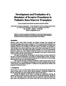
2.3. Development cycle Due to the demanding design principles and in particular the high accuracy-limited data paradox, an extensive support framework was established for CO2MPAS development. The development cycles of were divided into two distinct phases as demonstrated in Fig. 1, the Model Development Phase (MDP) and the Model Validation Phase (MVP). 1
786
CO2MPAS and its documentation are available online at (http://co2mpas.io)
Applied Energy 226 (2018) 784–796
G. Fontaras et al.
Sy Synth.Input Cases (7916 WLTP-NEDC
Development Phase
Simulations)
Model & submodules development update
WLTP & NEDC Simul. Quantities Improving?
Real Input Cases (63 WLTP-NEDC measured cases)
Real Datasets (28 MT , 19 AT & 1 CVT Vehicle),
Yes
Calibration and submodules optimization
Simul. CO2 & secondary metrics improving?
Bug Reports, User Feedback, Internal evaluations Yes
Noo
Final Model Set-up
Validation Phase
Synthetic Datasets (12 MT & 8 AT Vehicles)
Release
Fig. 1. CO2MPAS development cycle.
github.io/co2mpas/.
2.3.1. Model development For the MDP various industrial and research stakeholders provided actual test data and information about real vehicles. This data was subsequently used to create detailed simulation models in a commercial vehicle simulation software (AVL Cruise) [45,46]. The Cruise simulation results were used to create an extensive number of test cases. Because of data confidentiality issues, lack of a finalized WLTP version at the time, and the need to further detail and agree on the applicable NEDC test conditions, the creation of a broad test-case sample was necessary. MDP test-cases development process and the main findings of the activity are described in detail in [20,46,47]. In total twenty vehicles, twelve with manual transmission and eight with automatic transmission were simulated in Cruise over different operating conditions (150–200 depending on the vehicle) covering the European lightduty fleet composition to the extent possible. This resulted in a pool of 7916 test cases (triplets of simulated NEDC, WLTP-high and WLTP-low cycles) henceforward refer to as synthetic data.
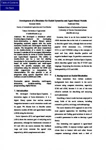
2.4. CO2MPAS characteristics The core of CO2MPAS is a backward-looking, longitudinal dynamics physical model simulating energy flow and losses at various components. Investigations [48] indicated that the four most important factors affecting CO2 emissions for WLTP and NEDC are, energy demand at the driveline, gear-shifting strategy for automatic transmission vehicles, hot and cold start engine fuel consumption, and the operation of specific fuel-saving technologies. In order to maximize accuracy and in lack of detailed input data CO2MPAS has an integrated self-calibration functionality. More details are provided in the subsequent paragraphs. 2.4.1. Model workflow CO2MPAS workflow is presented in Fig. 2. As a first step data from the WLTP certification test are provided as input combined with NEDC relevant parameters of the vehicle (eg. mass, road loads and test boundary conditions). The model then assigns specific and generic values that are standard according to the correlation process. Following, specific submodules, such as the temperature prediction, gear-shifting prediction, and power loss module are calibrated using the WLTP test data. Once this step finishes, an optimization loop takes place for configuring the engine submodule. The initial vehicle/engine model setup predicts the CO2 emissions over WLTP and is validated against the supplied WLTP measured values. In total, six fuel-consumption related parameters and two cold start related parameters are optimized. Once the optimization loop is finished, the final model configuration for the specific vehicle is used to predict the NEDC CO2 emissions. The process
2.3.2. Model validation Following the MDP, the resulting version of CO2MPAS entered the validation phase. During the MVP, CO2MPAS was assessed using only real measurement data (pairs or triplets of WLTP-high and/or WLTPlow and NEDC tests). Initially, the number of validation test data was limited but grew with time as the project evolved. The 2017 final validation phase of CO2MPAS was based on 48 tested vehicles (28 manual-transmission vehicles, 19 automatic-transmission vehicles, and one continuously variable transmission vehicle) tested over different configurations resulting in 63 WLTP-NEDC test cases. Detailed reports of all MDP and MVP results are publicly available at http://jrcstu. 787
Applied Energy 226 (2018) 784–796
G. Fontaras et al.
Fig. 2. CO2MPAS model logical flow-chart.
where a and Pmotive represent the acceleration and the motive power respectively, while i represents an inertial factor dependent on the number of dyno axes used during the test, and is equal to 0.015 for NEDC and 0.03 for WLTP (one axle mode and two axle mode respectively). Factors F0, F1, F2 are commonly used to characterize the road loads of vehicles; they express the constant part of a vehicle’s resistances (tire rolling resistance), the part that is proportional to velocity (partly tire rolling resistance partly drivetrain losses), and the
is concluded with the production of the necessary reports containing the results and information about the execution of CO2MPAS. 2.4.2. Drivetrain module Vehicle energy demand is calculated via simple vehicle longitudinal dynamics. The drivetrain module includes the various sub-models of the vehicle’s drivetrain, excluding the engine. Fig. 3 presents the outline of the Drivetrain Module and the various steps for the calculation of the engine speed and power demand. The calculation starts with a predefined velocity profile, and, respecting the energy equilibriums in the various steps, goes backward from the forces applied to the vehicle and the wheels, to the final drive, the gearbox, the clutch or torque converter, up to the required engine’s speed and power output. 2.4.2.1. Vehicle model. The first step of the calculation is to derive the motive energy required to move the vehicle at the respective velocity profile. The Vehicle Model starts from the velocity profile and calculates the acceleration profile and motive power, taking into account the vehicle mass, the road loads, and the various inertias, as described in the equations below.
a (t ) = dv (t )/ dt
(1)
Pmotive (t ) = (m ∗a (t ) + m ∗g ∗sin(φ) + F 0∗cos(φ) + F 1∗v (t ) + F 2∗v (t )2 + m ∗i ∗a (t )) ∗v (t )
Fig. 3. Drivetrain Module’s outline.
(2) 788
Applied Energy 226 (2018) 784–796
G. Fontaras et al.
drive efficiency in each time step. The final drive efficiency, ηfinal drive, is considered constant with its value depending on the type of driveline of the vehicle (2-wheel drive or 4-wheel drive).
part that is proportional to the square of the vehicle’s velocity (aerodynamic component). Variables m and g are the mass and acceleration of gravity respectively while φ is the road gradient (not used in regulatory cycles but can be used for simulation of on-road operation).
2.4.2.4. Gearbox model. The Gearbox Model calculates the gearbox’s input shaft speed, power, and torque, taking into account torque losses at the gearbox.
2.4.2.2. Wheels model. The Wheels Model calculates the wheel speed, power, and torque, starting from the velocity profile and motive power of the vehicle, as described in the equations below.
Nwheels (t ) = v (t )/2∗π ∗Rdynamic
(3)
Pwheels (t ) = Pmotive (t )
(4)
Twheels (t ) = Pwheels (t )/ Nwheels (t ) ∗2∗π
(5)
Nis (t ) = Nout (t ) ∗Rgearbox (t )i
2.4.2.3. Final drive model. The Final Drive Model calculates the final drive’s rotational speed, power, and torque, starting from the respective wheels figure and taking into account the various losses. (6)
Tfinal drive (t ) = Twheels (t )/ Rfinal drive + (1−ηfinal drive )/(ηfinal drive ∗Rfinal drive ) ∗Nwheels Pfinal drive (t ) = Pwheels (t )/(Twheels (t )/(Tfinal drive (t ) ∗Rfinal drive ))
Tis (t ) = Tos (t ) ∗Rgearbox (t )−i + Tgearbox loss
(10)
Tgearbox loss (t ) = (gbp01 ∗Tis (t )−gbp10 ∗Nis (t )−gbp00 )
(11)
where Tis is the torque at the gearbox input shaft and Tos the torque at the output shaft, Nis is the revolutions at the input shaft and Nout the revolutions at the output shaft respectively and gbpxy are empirically defined parameters that depend on the gearbox type (automatic, manual or CVT) and the gearbox temperature. The input shaft is considered as the shaft connected to the engine in case the torque output of the gearbox is positive and as the shaft connected to the vehicle final drive in case the torque output of the gearbox is negative. Similarly, exponent i is equal to 1 and −1 respectively. Since CO2MPAS operates as a backward model Tis, Tos, Nis, Nout are equal to Tfinal drve and Nfinal drive depending on the conditions. A generic Gearbox Temperature Model is included to account for the changes in gearbox torque losses due to cold start.
where Nwheels, Pwheels, and Twheels represent the wheels’ speed, power, and torque respectively, π stands for the mathematical pi constant, and Rdynamic is the dynamic rolling radius of the wheels.
Nfinal drive (t ) = Nwheels (t ) ∗Rfinal drive
(9)
(7) (8)
where Nfinal drive, Pfinal drive, and Tfinal drive represent the final drive’s speed, power and torque respectively, and Rfinal drive represents the final drive ratio. The second part of the right side of Eq. (7) represents the final drive losses, while the denominator of Eq. (8) represents the final
Tempgearbox (t ) = Qgearbox (t )/ m ∗c pgearbox + Tempinit
(12)
Qgearbox (t ) = Tgearboxloss (t ) ∗2∗pi∗Nis (t )/60
(13)
where Tempgearbox is the gearbox temperature, Qgearbox the heat released in the gearbox due to torque losses, m the mass and Cpgearbox the
Fig. 4. Example of automatic gear-shifting models (a: CMV, b: GSPV) based on real experimental tests. Dashed lines indicate downshift limits while solid lines indicate upshift limits. 789
Applied Energy 226 (2018) 784–796
G. Fontaras et al.
model allows the use of a higher gear at constant speed operation. 2.4.3.1. Clutch and torque converter. The Clutch/Torque Converter (TC) Model defines the rotational speed and power at the input shaft of the component. In both cases, an “RPM-slip” model is fitted based on experimental data. The RPM-slip provides the difference in the rotational speed at the entrance and exit of the component as a function of rotational acceleration during gearshift events. Additionally, the clutch/torque converter power is calculated using predefined torque transfer curves (k-factor curves) that have been defined empirically.
SR = Nclutch / tcout (t )/ Nclutch / tcin
(14)
ηclutch / tc (t ) = KF (SR) ∗SR
(15)
Nclutch / tcout (t ) = Ngearbox
(16)
Nclutch / tcin (t ) = Nclutch / tcout (t ) + RPMslip
(17)
Pclutch / tc (t ) = Pgearbox (t )/ ηclutch / tc (t )
(18)
Fig. 5. Engine Module’s outline.
In the above equations, ηclutch/tc stands for the clutch/torque converter efficiency which is provided by the k-factor curve (KF), while Nclutch/tc and Pclutch/tc represent the clutch/torque converter speed and power respectively. For the clutch, a linear torque transfer curve as a function of the ratio of the rotational speeds is used whereas for torque converters a non-linear function is used. For TCs a lock-up velocity is set to 48 km/h above which RPM-slip is considered to be zero.
equivalent heat capacity of the gearbox. In addition to the previous, the gear-shifting profile must be provided or calculated. For that purpose, the model is divided into submodels, for the two main transmission types: manual and automatic. 2.4.3. Automatic transmission gearshifting For manual transmission vehicles, gear shifting over the NEDC is straightforward as the respective test protocol foresees specific shifting points. However, the accurate prediction of gear shifts over the NEDC is crucial for Automatic Transmission (AT) vehicles. Two methods are included in CO2MPAS for AT gearshifting for official purposes, the Constant gear-shifting Velocity Matrix (CMV) and the GearShift PowerVelocity matrix (GSPV). The CMV simulates the up-shifting and down-shifting only as a function of vehicle velocity. Practically upshifts and downshifts occur at fixed velocity points. GSPV simulates upshift as a function of both vehicle velocity and motive power at the wheels, with a different curve applicable per gear. CO2MPAS does not operate on predefined CMV – GSPV matrices but calculates them per each vehicle using the WLTP test data. Once calculated, a validation comparing with the test data takes place and the model that exhibits the best capacity to predict engine RPM over WLTP is selected automatically. Two sets of gear-shift maps are calculated, one for hot and one for cold conditions. In particular, for CVT a gradient boost regressor is calibrated based on WLTP data and used to predict engine speed as a function of vehicle speed, acceleration, and power at the gearbox over NEDC. Typical examples of the CMV and GSPV methods are presented in Fig. 4. Dashed lines in the figure indicate the downshift limit line while solid lines indicate the upshift line (CMV method) or curve (GSPV method). Dots demonstrate the actual gearsihfting points that occur during the calibration cycle and which are used for calibrating the two models. To avoid instabilities in gear shifting and better reflect the actual operation over constant speed driving the gears predicted by the CMV or GSPV method are also corrected according to the following:
2.4.4. Engine module The Engine Module includes the various sub-models related to the calculation of fuel consumption, starting from the engine’s required speed and power from the drivetrain and the engine temperature. Fig. 5 presents the main outline of the Engine Module. Engine power is derived from the following equation:
Peng = Pdtr + Pelc + Pmec
(19)
Pelc = Pelect /(ηalt ∗ηbat )
(20)
Pmec = Tmec ∗ω or constant value
(21)
where Pdtr is the power requested at the driveline, Pelc is the power demand for the vehicle’s electrical system, e.g. the alternator power demand, and Pmec represents additional mechanical losses from systems connected to the engine’s shaft, e.g. pumps. Pdtr is calculated as described in previous paragraphs. Pelect is calculated based on the info extracted from the WLTP input data. The battery and alternator efficiencies, ηbat and ηalt respectively, are considered to be constant. It shall be noted here that the Electrics Model, even though not directly related with the engine, is included in the Engine Module, as it is not a direct part of the drivetrain. The alternator is presumed to be mechanically connected to the engine Pmec can be set to a constant value or as fixed mechanical torque loss, Tmec. Variable ω denotes the angular speed of the engine. Some common energy saving technologies, such as startstop and brake energy recuperation system, are incorporated. They are simulated by a generic operating strategy which takes into account vehicle motion state and other vehicle characteristics. More details are provided in subsequent paragraphs.
(a) Full Load Curve: the engine power demand at the resulting engine speed cannot exceed th full-load-curve power output of the engine (applicable also to MT vehicles). (b) Minimum Engine speed: the resulting rotational speed shall not be less than the idle engine speed of the vehicle. (c) Velocity Limits: the resulting vehicle velocity shall not exceed the limits provided by the Velocity Limits Matrix (MVL), defined as the minimum and maximum velocity allowed for each gear at quasisteady-state conditions. The MVL is also calibrated using WLTP data. (d) If the vehicle is equipped with a fuel-saving gear-shifting mode, the
2.4.4.1. Fuel consumption module and calibration. Fuel consumption is calculated by an extended Willans Lines Model [49,50]. It is represented as follows:
BMEP (t ) = a2∗VMEP 2 + (a + b∗Cm (t ) + c ∗Cm (t )2) VMEP + (T (t )/ Ttrg )−k ∗FMEP
(22)
where:
Cm (t ) = 2∗N ∗s /60 790
(23)
Applied Energy 226 (2018) 784–796
G. Fontaras et al.
BMEP (t ) = 2∗Peng ∗60/(CC∗N )
(24)
FC (t ) = VMEP (t ) ∗CC∗v /60/(2∗FLHV )
(25)
FMEP (t ) = l + l2∗Cm (t )2
(26)
2.4.5.1. Start/stop model. The engine start-stop model defines when the engine should be switched off. Users provide as input the minimum start-stop activation time. Using WLTP test data CO2MPAS calculates a status variable, on or off. as a function of the vehicle’s velocity and acceleration. Following, CO2MPAS calibrates a classifier in order to associate engine switch off events to vehicle deceleration, velocity and battery state of charge.
VMEP stands for Fuel Consumption Mean Effective Pressure: it represents a normalized quantity to the engine’s capacity, representative of fuel consumption. Similarly, BMEP stands for the engine’s Brake Mean Effective Pressure. Cm stands for the engine Mean Piston Speed. FMEP is the engine friction mean effective pressure. T it the engine’s temperature, Ttrg is the target operating temperature of the engine, N, s, and CC are engine speed, engine stroke, and engine capacity, respectively, and FLHV is the fuel lower heating value. Lastly, parameters a, b, c, a2 relate to the thermodynamic efficiency of the engine, while l and l2 correspond to the engine’s losses (friction, pumping, etc.). The normalized equation above (20) allows for engine rescaling to different engine capacities and engine speed operating ranges. During the CO2MPAS engine calibration loop, the values of the parameters a, b, c, a2, l, l2, and k are optimized. An initial estimate of the instantaneous (second by second) CO2 emissions of the vehicle over WLTP is made based on generic values for the parameters. This initial estimate is then rescaled for each sub-cycle so that the integral of CO2 emissions over the subcycle is equal to the measured CO2 values (rescaled CO2 time series). A fitting algorithm calculates new values for the parameters minimizing the error between the rescaled CO2 time series and the ones simulated. The process is repeated until convergence is achieved to given parameter values, with a maximum number of iterations set to 100. As the last step, a final optimization is done solely on the basis of minimizing the error of the CO2 time series integral per WLTP subcycle against the measured CO2 values.
2.4.5.2. Alternator model. The alternator model comprises 2 parts, the logic part that defines when the alternator operates and how, and the physical part that defines how much current is supplied by the alternator and hence how much power is absorbed from the engine. The logic part identifies different phases of alternator operation such as idling, regenerative braking, battery charging, battery depletion and associates those with specific vehicle operating conditions. The physical part identifies the current’s supply per each phase associating it with engine speed, battery state of charge and vehicle deceleration. A gradient boost regressor is calibrated using the logic and physical data extracted from the WLTP cycle. Current prediction takes place considering the abovementioned parameters. It should be noted that the alternator logic is set to maintain a fixed battery state of charge, which is identified based on the WLTP alternator and battery current data. A fixed initial battery state of charge for WLTP is set at 90% of maximum capacity. 2.4.5.3. Engine technologies. A series of fuel-saving technologies are currently simulated using the extended Willans approach described previously and empirical fuel reduction factors. For gasoline engines, those are variable valve actuation, lean combustion type, and cylinder deactivation. For diesel engines, the technologies are external EGR and cylinder deactivation. The engine parameters are modified according to empirical correction factors [51] that result in lower or in some cases higher fuel consumption depending on the type of technology. The technology is not applied uniformly across the entire operation field of the engine but within predefined areas. These areas are defined using the maximum and minimum mean piston speed over which the technology is relevant and the maximum and minimum break mean effective pressure. These technologies are considered during the calibration process of the engine model.
2.4.4.2. Engine temperature prediction. A regressor is used to predict the instantaneous engine temperature differential as a function of engine speed, acceleration, and power at the gearbox. The regressor is calibrated based on WLTP recorded time series using Gradient Boost algorithm (Ransac algorithm used for inlier and outlier detection). This approach allows for significantly faster model calibration, as the engine temperature calculation is not influenced by the engine fuel consumption, which is calibrated at a later stage. A semi-empirical energy-balance based approach for engine temperature prediction has also been investigated and is considered as a supplementary option for future releases.
3. Results and discussion The results of the final MDP, the final MVP and the feedback obtained during the first six months of CO2MPAS’ official use are presented below. Results are grouped according to vehicle engine (gasoline or diesel), gearbox (MT or AT) and test-vehicle configuration (high or
2.4.5. Other technologies A series of fuel-saving technologies are included in the model and simulated.
Fig. 6. WLTP to NEDC CO2 [g/km] for the MDP (a: High vehicle configuration, b: High vehicle configuration). 791
Applied Energy 226 (2018) 784–796
G. Fontaras et al.
vehicle configuration low ones. The CO2 results of the final MVP are summarized in Fig. 9. The test results confirm the observations of the MDP sample. There is a strong linear correlation between the emissions measured over the two cycles. In the case of vehicle configuration, high diesel vehicles appear to increase their emissions over WLTP more than gasoline ones while in the case of vehicle configuration low WLTP appears to affect both types of powertrain in the same way. WLTP measurement results are 5–20% higher compared to the NEDC ones. However, as the emissions of vehicles increase the difference between NEDC and WLTP emissions becomes smaller. When looking at the CO2MPAS’ accuracy in predicting the NEDC emissions the main findings of the MDP are also verified by the results obtained from the MVP sample. As presented in Fig. 10 the error distribution of the MVP was similar to that of the MDP for manual transmission vehicles, although 40% of the MVP sample consisted of automatic transmission vehicles. The average error over NEDH-H was −0.31% with a standard deviation of 2.51% (Table 3). The respective numbers for NEDC-L were −1.34% and 2.65, over a much smaller sample, however; 93.6% and 85.7% of the cases being inside the ± 4% range. In particular, for the automatic transmission vehicles, the average error was −0.8% and the standard deviation 2.3% over all cycles, while the same numbers for manual transmission vehicles were −0.3% and 2.7% respectively. No particular bias of the CO2MPAS in the case of specific automatic transmission vehicles was found. No particular influences of the engine type (gasoline/diesel) were observed and similar average error values and standard deviation were calculated. Table 3 provides the details of MVP error statistics.
low). 3.1. Development and validation phase results 3.1.1. MDP results The CO2 results of the final MDP are summarized in Fig. 6. The sample included 3958 synthetic test cases for each configuration (high/ low). The sample included vehicles with emissions ranging from 100 to 250 gCO2/km covering the vast majority of the European LDV fleet. There appears to be a strong linear correlation between the emissions simulated over the two cycles. The WLTP appears to influence more diesel vehicles compared to gasoline ones, particularly the vehicle configuration high. The low WLTP configuration yielded emissions close to those of NEDC while the high configuration resulted in higher overall emissions, increase that ranged in the order of 10–30% depending on the conditions. The results are consistent with those reported previously in the literature [20,47]. Focusing further on the accuracy of CO2MPAS, Figs. 7 and 8 present the error distribution of the model for all MDP test cases for MT and AT vehicles. Similarly, Tables 1 and 2 provide the details of the statistical analysis on the corresponding error. For manual transmission vehicles, the average error of the NEDC CO2 prediction in the MDP sample (2495 cases) is −0.45% for the NEDC-H configuration and −0.04% for the NEDC-L one. The standard deviations of the error are 2.67 and 2.26% accordingly (Table 1). The majority of the cases have an error within ± 5% of their target CO2 emission on NEDC, 85.6% have an error within ± 4% over NEDC-H, and 92.4% over the NEDC-L. The median of the distribution of the error is centered (Fig. 7). The maximum underestimation is −7.3% and −5.3% for NEDC H and NEDC L respectively while the maximum overestimations are 6.8% and 6.9%. These values suggest that more than 90% of the sample could be type approved directly using the CO2MPAS result for validation while for the rest of the vehicles a real chassis dyno test would be required. Regarding engine technology, the results are similar. Diesel vehicles (976 cases) present average errors of 0.4% and 1.0% respectively for NEDC-H and L with standard deviations of 2.8 and 2.0%. For gasoline vehicles (1519 cases), NEDC-H average error is of −1% with a standard deviation of 2.39% and NEDC-L average error is of −0.7% with a standard deviation of 2.1%. No statistically significant differences in the model’s CO2 prediction capacity was found between gasoline and diesel vehicles. Considering the automatic transmission vehicles, 1463 different synthetic test cases were used for CO2MPAS development. The average error performance is similar as in the case of manual transmission vehicles (errors of −0.18% and −0.44% observed see Table 2). However, the spread of the distribution is wider (see Fig. 8) with standard deviations of the order of 3.6% in all cases, about 1% higher than in the case of manual transmission vehicles. The increase in the error spread was initially associated with limitations in CO2MPAS’ automatic transmission logic to fully capture the NEDC gear-shifting of certain vehicles. This increased the variability, with 70 and 75% of the cases achieving the ± 4% error range for H and L configurations respectively. As will be presented later this behavior is not observed in the data received from real type-approved vehicles or the sample of vehicles used in the model validation phase. Engine type did not significantly influence the average model error with gasoline engine vehicles (840 cases) presenting average errors of 0.17% (NEDC-H) and 0.24% (NEDC-L) while diesel engine vehicles (623 cases) presented average errors of −0.64% and −1.37% respectively. The standard deviations of the error of the order of 4.4% for gasoline vehicles and 2% for diesel vehicles.
3.2. In-use results Every time that CO2MPAS is officially used for certifying the CO2 emissions of a vehicle, the EC receives a notification about the outcome of the simulation and the status of the model’s operation. The information received contains the deviation between the NEDC CO2 value declared officially by the vehicle OEM and the value predicted by CO2MPAS. This apparent error allows an indicative assessment of the accuracy of CO2MPAS. The terms apparent error and indicative are used because the declared value is not necessarily linked to a specific test result but is rather a qualified estimate made by the manufacturer regarding the NEDC CO2 emissions of the vehicle. At this point, it is noted that a random sampling procedure is foreseen by the correlation legislation to avoid that CO2MPAS results are exploited for artificially achieving lower emissions. Hence, the apparent CO2MPAS error is considered to be a reliable proxy for the behavior of the model. This section provides a summary of the feedback gathered in the period July 2017–January 2018. In the first months of CO2MPAS deployment, the EC received
3.1.2. MVP results The MDP dataset was used for CO2MPAS development. The validation of the model was done against real experimental data. The sample, in this case, included 47 vehicle configuration high tests and 16
Fig. 7. MDP NEDC prediction error distribution Manual Transmission vehicles. 792
Applied Energy 226 (2018) 784–796
G. Fontaras et al.
Fig. 8. MDP NEDC prediction error distribution Automatic Transmission vehicles.
Fig. 10. MVP NEDC prediction error distribution. Table 3 MVP NEDC error statistics.
Table 1 MDP NEDC error statistics Manual Transmission Vehicles.
Average St. Dev. Min. Max. Percent within ± 4% Percent within ± 2.5% P75-P25 Count
NEDC-H [%]
NEDC-L [%]
−0.45 2.67 −7.39 6.84 85.6 58.7 3.72 2495
−0.04 2.26 −5.28 6.91 92.4 73.1 3.37 2495
Averages StdDev Minimum Maximum Cases in ± 4% Cases in ± 2.5% P75-P25 Count
NEDC-L [%]
−0.31 2.51 −4.99 4.22 93.6 61.7 4.11 47
−1.34 2.65 −7.37 2.38 87.5 68.8 3.25 16
Table 4 TA sample characteristics.
Table 2 MDP NEDC error statistics Automatic Transmission Vehicles.
Averages StdDev Minimum Maximum Cases in ± 4% Cases in ± 2.5% P75-P25 Count
NEDC-H [%]
NEDC-H [%]
NEDC-L [%]
Transmission type
Automatic
Manual
CVT
−0.18 3.68 −7.4 12.53 70.7 47.6 4.82 1463
−0.44 3.66 −7.31 14.2 75.6 50 4.07 1463
Fuel Type Engine capacity list
Diesel
Gasoline
Diesel
Gasoline
Gasoline
1800–2200 cc > 2200 cc 1400–1800 cc < 1000 cc 1000–1400 cc
113 50 14 0 0
33 11 9 4 4
46 0 23 0 0
9 1 15 22 23
0 1 5 1 6
201 63 66 27 33
Total
177
61
69
70
13
390
Fig. 9. WLTP to NEDC CO2 [g/km] for the MVP (a: High vehicle configuration, b: High vehicle configuration). 793
Total
Applied Energy 226 (2018) 784–796
G. Fontaras et al.
existing, NEDC-based, one where an OEM declared a representative CO2 value for the vehicle undergoing type approval. Under the former procedure, the NEDC test results obtained from a chassis-dyno test were used to verify the declared value, within an uncertainty margin of 4%. CO2MPAS is used as a replacement for the chassis dyno test in order to facilitate the process and reduce the experimental costs. As shown previously, the CO2MPAS error in predicting NEDC CO2 is comparable to the uncertainty of the chassis dyno test foreseen by the NEDC legislation; its average error (bias) close to 1%. Thus in most cases, the OEM declared value is directly accepted as confirmed by the in-use results. If CO2MPAS prediction is higher than 4% compared to the declared CO2 value, the vehicle OEM is given the possibility to perform a physical test in order to prove the validity of the declared value. On the other hand, in order to avoid artificially low CO2 declarations in cases where CO2MPAS result is lower than −4% compared to the NEDC measurement, a measurement-based safeguard clause has been introduced. According to the regulation, 10% of the type-approved vehicles are randomly sampled and physically tested over the NEDC regardless of the CO2MPAS’ prediction. In case this random testing indicates an attempt by the OEM to exploit the CO2MPAS results for achieving lower CO2 emissions, a CO2 penalty is applied across the entire fleet of the OEM. This can indirectly lead to severe penalties in case the increase triggers non-compliance to the established CO2 standards. In the sample of vehicles investigated previously, about 1/3 will eventually undergo also an NEDC measurement. It should be noted however that the correlation procedure, whilst not changing the NEDC test procedure, provides further details and clarity on some of the NEDC testing conditions and this may also have an impact on the reported NEDC CO2 value. If there are differences in the NEDC CO2 emissions following the correlation procedure as compared to NEDC CO2 values that were type approved for the same or a similar vehicle prior to September 2017, those differences may be due to the fact that existing NEDC test conditions have been clarified in the correlation. Regulations are being applied and interpreted in the same way by all manufacturers and type approval authorities. For example, NEDC temperature has been fixed to 25 C, when previously a range of possible temperatures was acceptable, and the way the NEDC road loads are being determined has changed. Moreover, it should be noted that the same vehicle model and variant may have been modified in order to comply with the new requirements on pollutant emissions testing of light-duty vehicles, fact that in turn may also have an impact on NEDC CO2 values. Contrary to CO2MPAS itself, these elements may have a nonmarginal impact on the reported NEDC CO2 value.
notifications corresponding to 390 Vehicle WLTP-High and 313 Vehicle WLTP-Low configurations officially type approved (TA-sample). The above figures correspond to 390 unique vehicles receiving type approval during the aforementioned period. Table 4 reports a summary of the characteristics of the sample. The majority of the vehicles certified in the reporting period were diesel and automatic transmission vehicles with an engine capacity in the range 1800–2200 cm3. Fig. 11 and Table 5 report the main characteristics of the error distribution of the TA sample. The average CO2MPAS error is 1.9% (CO2MPAS overprediction) for vehicle configuration High and 1.4% for vehicle configuration Low. More importantly, the percentage of vehicles with an error lower than 4%, the acceptance limit set in the regulation, is 70% for the vehicle configuration high and 77% for the low configuration. Still considering the 10% randomly selected vehicles that are subjected to NEDC physical testing for control purposes, it is expected that more than two-thirds of the type approved vehicles use CO2MPAS, reducing considerably the associated testing burden, i.e., no need to undergo a physical chassis dyno test. The CO2MPAS overprediction (positive bias of 1.4–2% on average in the declared CO2 value but) is similar to the experimental test procedures tolerances. What is probably an unexpected result is the variability of the prediction that is higher compared to both MDP and MVP results, at 5.5% for NEDC-H and 5.8 for NEDC-L configurations. To a certain extent, this can be attributed to the learning effect, as engineers involved in the certification process, both inside the manufacturers and at authorities supervising the process, had to implement a new data measurement, handling and analysis procedure. Indeed the JRC has received multiple communications regarding possible problems and questions on the appropriate implementation of CO2MPAS, particularly in the first months of its official use. For certain outliers where CO2MPAS error exceeded 10% the input data provided had quality issues that lead to higher errors (e.g. erroneous time alignment). Certain cases where the simulation itself has failed to produce an accurate result have been identified and discussed with the respective user in order to improve the model in future releases. Fig. 12 presents the CO2MPAS prediction error split per engine fuel type (chart a for diesel and b for gasoline) and per transmission type (chart c for automatic transmission and d for manual transmission). The pictures obtained are very similar to that of the general fleet discussed above. Average errors for diesel engines are 2.8% and 1% for high and low configuration respectively and 0.6% and 2.6% for gasoline ones. The standard deviations are also in this case of the order of 5.5%. The 4% acceptance limit is met by 67% (diesel configuration high) up to 80% (diesel configuration low) of the sample. Looking at transmission type, the average errors for automatic vehicles are 2% and 0.5% for configuration high and low respectively. The same numbers increase to 2.5% and 3.4% in the case of manual transmission vehicles. The standard deviation of the samples remains of the order of 5.5%. The 4% acceptance limit is achieved by 63% (manual, high configuration) to 85% (automatic, low configuration) of the sample. It is difficult to extract solid conclusions as to possible reasons leading to the differences in the error distributions between the different technology types. So far no particular model failure has been identified that could explain this situation. In particular, the high error observed for manual transmission vehicles (high configuration) was unexpected as for these vehicles gearshifting is standardized hence the simulation process is more straightforward with less unknown factors. Further analysis is necessary to understand if this situation can be traced to implementation issues. 3.3. Influence of CO2MPAS in official CO2 monitoring Based on the findings presented above and considering how the type approval process takes place, CO2MPAS itself is likely to have only a marginal effect on the reported CO2 emissions from light-duty vehicles in Europe. It is important to note that the CO2MPAS CO2 estimate is not the official certification value. The current process replicates the pre-
Fig. 11. Distribution of apparent CO2MPAS error. 794
Applied Energy 226 (2018) 784–796
G. Fontaras et al.
Table 5 Apparent CO2MPAS error statistics.
Count Mean St. dev. 25% 50% 75% < 4%
NEDC-H [%]
NEDC-L [%]
388 1.9 5.5 −0.7 2.1 4.5 70
313 1.4 5.8 −0.5 1.3 3.8 77
• •
4. Conclusions
physical testing was probably necessary to complete the type approval process. In the context of the above numbers, one should consider the learning effect in the application of the entire process. It is expected that over time the error profile might improve. A random sampling and testing process is also in place to safeguard the proper use of the simulator and the validity of the correlation results. Intentional misuse of CO2MPAS is linked to corrections of the manufacturer’s CO2 emissions across the fleet. The use of CO2MPAS does not affect the reported NEDC CO2 emissions as, eventually, it is the OEM declared-value that is used for monitoring and reporting purposes.
Regarding future activity and developments, given the expected shift towards hybrid and electric powertrains in the years to come, the development team is working on the necessary adaptations for covering also electric powertrains and conventional vehicle operation over broader operating conditions. The authors are investigating the possibility of calibrating CO2MPAS using real-world measurement data in order to extend the tool’s applicability to fuel consumption prediction over real-world operation for consumer information and research purposes.
The paper presented the main characteristics of the CO2MPAS model and analyzed the results obtained from its development, validation and official operation (as of January 2018). The CO2MPAS model was developed in order to facilitate and accelerate the introduction of the WLTP in the European regulatory framework by reducing the time and costs needed for certifying vehicles over both WLTP and NEDC during the transition period. CO2MPAS does so by substituting the necessary extra chassis dyno test with computer simulation. The main conclusions drawn are:
Acknowledgments
• CO MPAS achieves low errors in the prediction of the NEDC cycle 2
•
which in the controlled sample used for its development are of the order of 1% with a standard deviation of 3% while in actual operation the respective numbers appear to be of the order of 1.5% and 5% respectively. In-use results show that for about 2/3 of the newly certified vehicles the manufacturer’s declared value was validated with CO2MPAS, avoiding additional experimental testing; for the remaining ones
Authors are grateful to all the staff of the VELA/JRC and LAT/AUTH laboratories who have been involved in extensive experimental testing throughout the last 4 years for the needs of the project. The authors would like to thank Mr. Iker Prado and Mr. Alessandro Tansini for their invaluable support in the validation of CO2MPAS and Mr. Cosmin Codrea and Mrs. Susanna Lindvall for their comments.
Fig. 12. Error distribution per fuel type (a: diesel, b: gasoline) and transmission type (c: automatic, d: manual). 795
Applied Energy 226 (2018) 784–796
G. Fontaras et al.
References [27]
[1] EEA. Total greenhouse gas emissions by sector (%) in EU-27, 2009; 2012. [2] European Commission. Reducing emissions from transport; 2015. (accessed January 12, 2015). [3] EEA. Final energy consumption by sector and fuel — European Environment Agency; 2015. (accessed August 25, 2016). [4] Fontaras G, Samaras Z. A quantitative analysis of the European Automakers’ voluntary commitment to reduce CO2 emissions from new passenger cars based on independent experimental data. Energy Policy 2007;35:2239–48. http://dx.doi.org/ 10.1016/j.enpol.2006.07.012. [5] Fontaras G, Samaras Z. On the way to 130gCO2/km—Estimating the future characteristics of the average European passenger car. Energy Policy 2010;38:1826–33. http://dx.doi.org/10.1016/j.enpol.2009.11.059. [6] Fontaras G, Zacharof N-G, Ciuffo B. Fuel consumption and CO2 emissions from passenger cars in Europe-Laboratory versus real-world emissions. Prog Energy Combust Sci 2017;60:97–131. [7] Fontaras G, Franco V, Dilara P, Martini G, Manfredi U. Development and review of Euro 5 passenger car emission factors based on experimental results over various driving cycles. Sci Total Environ 2014;468:1034–42. http://dx.doi.org/10.1016/j. scitotenv.2013.09.043. [8] May J, Favre C, Bosteels D. Emissions from Euro 3 to Euro 6 light-duty vehicles equipped with a range of emissions control technologies. Intern. combust. engines perform. fuel econ. emiss. Woodhead Publishing; 2013. p. 55–65. http://dx.doi.org/ 10.1533/9781782421849.2.55. [9] 2007/46/EC. Directive 2007/46/EC of the European Parliament and of the Council of 5 September 2007 Establishing a framework for the approval of motor vehicles and their trailers, and of systems, components and separate technical units intended for such vehicles; 2007. [10] UNECE. Regulation No. 83 Addendum 82: concerning the adoption of uniform technical prescriptions for wheeled vehicles, equipment and parts which can be fitted an d/or be used on wheeled vehicles and the conditions for reciprocal recognition of approvals granted on the basis of these prescriptions; 2011. [11] Franco V, Kousoulidou M, Muntean M, Ntziachristos L, Hausberger S, Dilara P. Road vehicle emission factors development: a review. Atmos Environ 2013;70:84–97. http://dx.doi.org/10.1016/j.atmosenv.2013.01.006. [12] Marotta A, Pavlovic J, Ciuffo B, Serra S, Fontaras G. Gaseous emissions from lightduty vehicles: moving from NEDC to the new WLTP test procedure. Environ Sci Technol 2015;49:8315–22. http://dx.doi.org/10.1021/acs.est.5b01364. [13] Contag M, Li G, Pawlowski A, Domke F, Levchenko K, Holz T, et al. How they did it: an analysis of emission defeat devices in modern automobiles; 2017. [14] Anenberg SC, Miller J, Minjares R, Du L, Henze DK, Lacey F, et al. Impacts and mitigation of excess diesel-related NOx emissions in 11 major vehicle markets. Nature 2017;545:467–71. http://dx.doi.org/10.1038/nature22086. [15] Weiss M, Bonnel P, Hummel R, Provenza A, Manfredi U. On-road emissions of lightduty vehicles in Europe. Environ Sci Technol 2011;45:8575–81. http://dx.doi.org/ 10.1021/es2008424. [16] Tietge U, Diaz S, Mock P, German J, Bandivadekar A, Ligterink N. White paper from laboratory to road: a 2016 update of official and “real-world” fuel consumption and CO2 values for passenger cars in Europe; 2016. [17] UNECE. Global technical regulation No. 15. worldwide harmonized light vehicles test procedure. Geneva: UNECE; 2015. [18] European Commission. Regulation (EC) 2017/1151 of 1 June 2017 supplementing Regulation (EC) No 715/2007 of the European Parliament and of the Council on type-approval of motor vehicles with respect to emissions from light passenger and commercial vehicles (Euro 5 and Euro 6) and on access to vehicle repair and maintenance information, amending Directive 2007/46/EC of the European Parliament and of the Council, Commission Regulation (EC) No 692/2008 and Commission Regulation (EU) No 1230/2012 and repealing Commission Regulation (EC) No 692/2008; 2017. [19] Pavlovic J, Anagnostopoulos K, Clairotte M, Arcidiacono V, Fontaras G, Rujas IP, et al. Dealing with the gap between type-approval and in-use light duty vehicles fuel consumption and CO2 emissions: present situation and future perspective. Transp Res Rec J Transp Res Board 2018. http://dx.doi.org/10.1177/0361198118756894. 036119811875689. [20] Tsokolis D, Tsiakmakis S, Dimaratos A, Fontaras G, Pistikopoulos P, Ciuffo B, et al. Fuel consumption and CO2 emissions of passenger cars over the new worldwide harmonized test protocol. Appl Energy 2016;179:1152–65. [21] Alam MS, Hyde B, Duffy P, McNabola A. Assessment of pathways to reduce CO2 emissions from passenger car fleets: case study in Ireland. Appl Energy 2017;189:283–300. http://dx.doi.org/10.1016/j.apenergy.2016.12.062. [22] European Commission. Regulation (EC) No 443/2009 of the European Parliament and of the Council setting emission performance standards for new passenger cars as part of the Community’s integrated approach to reduce CO2 emissions from lightduty vehicles; 2009. [23] Dimaratos A, Tsokolis D, Fontaras G, Tsiakmakis S, Ciuffo B, Samaras Z. Comparative evaluation of the effect of various technologies on light-duty vehicle CO2 emissions over NEDC and WLTP. Transp Res Procedia 2016;14:3169–78. [24] Pavlovic J, Marotta A, Ciuffo B, Serra S, Fontaras G, Anagnostopoulos K, et al. Correction of test cycle tolerances: evaluating the impact on CO2 results. Transp Res Procedia 2016;14:3099–108. [25] Fontaras G, Ciuffo B, Zacharof N, Tsiakmakis S, Marotta A, Pavlovic J, et al. The difference between reported and real-world CO2 emissions: how much improvement can be expected by WLTP introduction? Transp Res Procedia 2017;25:3937–47. [26] Suarez-Bertoa R, Zardini AA, Keuken H, Astorga C. Impact of ethanol containing gasoline blends on emissions from a flex-fuel vehicle tested over the Worldwide
[28]
[29]
[30]
[31] [32]
[33]
[34]
[35]
[36]
[37]
[38]
[39]
[40]
[41]
[42]
[43]
[44]
[45] [46]
[47]
[48]
[49] [50]
[51]
796
Harmonized Light duty Test Cycle (WLTC). Fuel 2015;143:173–82. http://dx.doi. org/10.1016/j.fuel.2014.10.076. Tsiakmakis S, Fontaras G, Ciuffo B, Samaras Z. A simulation-based methodology for quantifying European passenger car fleet CO2 emissions. Appl Energy 2017;199:447–65. Fontaras G, Ciuffo B, Tsiakmakis S, Anagnostopoulos K, Marotta A, Pavlovic J, et al. A simplified technology-specific simulation approach for the estimation of CO2 emissions from traffic simulation models. In: 94th Annu. Meet. Transp. Res. Board; 2015. European Commission. Regulation (EU) 2017/1152 of 2 June 2017 setting out a methodology for determining the correlation parameters necessary for reflecting the change in the regulatory test procedure with regard to light commercial vehicles and amending Implementing Regulation (EU) No 293/2012. vol. Official Journal of the European Union L 175; 2017. European Commission. Regulation (EU) 2017/1153 of 2 June 2017 setting out a methodology for determining the correlation parameters necessary for reflecting the change in the regulatory test procedure and amending Regulation (EU) No 1014/2010. vol. Official Journal of the European Union. L 175; 2017. Ciuffo B, Fontaras G. Models and scientific tools for regulatory purposes: the case of CO 2 emissions from light duty vehicles in Europe. Energy Policy 2017;109:76–81. Fontaras G, Kouridis H, Samaras Z, Elst D, Gense R. Use of a vehicle-modelling tool for predicting CO2 emissions in the framework of European regulations for light goods vehicles. Atmos Environ 2007;41:3009–21. http://dx.doi.org/10.1016/j. atmosenv.2006.12.004. Lee S, Lee B, Zhang H, Sze C, Quinones L, Sanchez J. Development of greenhouse gas emissions model for 2014–2017 heavy- and medium-duty vehicle compliance. SAE Int 2011. http://dx.doi.org/10.4271/2011-01-2188. Technologies and approaches to reducing the fuel consumption of medium- and heavy-duty vehicles. Washington, D.C.: National Academies Press; 2010. 10.17226/ 12845. Lee H, Choi H, Park M, Min K, Lee N, Park J, et al. Development of a vehicle system model for the first medium- and heavy-duty commercial vehicle fuel efficiency standards in Korea. In: SAE tech. pap. SAE International; 2015. 10.4271/2015-012774. Fontaras G, Rexeis M, Dilara P, Hausberger S, Anagnostopoulos K. The development of a simulation tool for monitoring heavy-duty vehicle CO2 emissions and fuel consumption in Europe. In: SAE Tech. Pap., SAE International; 2013. 10.4271/ 2013-24-0150. Morita K, Shimamura K, Yamaguchi S, Furumachi K, Osaki N, Nakamura S, et al. Development of a fuel economy and exhaust emissions test method with HILS for heavy-duty HEVs. SAE Int J Engines 2008;1:873–87. http://dx.doi.org/10.4271/ 2008-01-1318. Mozafar MR, Amini MH, Moradi MH. Innovative appraisement of smart grid operation considering large-scale integration of electric vehicles enabling V2G and G2V systems. Electr Power Syst Res 2018;154:245–56. http://dx.doi.org/10.1016/ j.epsr.2017.08.024. Amini MH, Moghaddam MP, Karabasoglu O. Simultaneous allocation of electric vehicles’ parking lots and distributed renewable resources in smart power distribution networks. Sustain Cities Soc 2017;28:332–42. http://dx.doi.org/10.1016/ j.scs.2016.10.006. Bishop JDK, Martin NPD, Boies AM. Quantifying the role of vehicle size, powertrain technology, activity and consumer behaviour on new UK passenger vehicle fleet energy use and emissions under different policy objectives. Appl Energy 2016;180:196–212. http://dx.doi.org/10.1016/j.apenergy.2016.07.111. Du J, Ouyang D. Progress of Chinese electric vehicles industrialization in 2015: a review. Appl Energy 2017;188:529–46. http://dx.doi.org/10.1016/j.apenergy. 2016.11.129. Falcão EAM, Teixeira ACR, Sodré JR. Analysis of CO2 emissions and techno-economic feasibility of an electric commercial vehicle. Appl Energy 2017;193:297–307. http://dx.doi.org/10.1016/j.apenergy.2017.02.050. Commission Implementing Regulation (EU) 2017/1153 of 2 June 2017 setting out a methodology for determining the correlation parameters necessary for reflecting the change in the regulatory test procedure and amending Regulation (EU) No 1014/2010; n.d. Arcidiacono V, Tsiakmakis S, Fontaras G, Ciuffo B, Valverde V, Pavlovic J, et al. CO2MPAS interactive workflow chart; 2018. . AVL CRUISE™ - avl.com; n.d. (accessed July 11, 2017). Tsokolis D, Tsiakmakis S, Triantafyllopoulos G, Kontses A, Toumasatos Z, Fontaras G, et al. Development of a template model and simulation approach for quantifying the effect of WLTP introduction on light duty vehicle CO2 emissions and fuel consumption, SAE Technical Paper; 2015. Tsokolis D, Dimaratos A, Samaras Z, Tsiakmakis S, Fontaras G, Ciuffo B. Quantification of the effect of WLTP introduction on passenger cars CO2 emissions. J Earth Sci Geotech Eng 2017;7. Tsiakmakis S, Ciuffo B, Fontaras G, Anagnostopoulos K, Arcidiacono V, Praksova R, et al. Introducing a new emissions certification procedure for european light-duty vehicles: monte carlo simulation of the potential effect on fleet carbon dioxide emissions. Transp Res Rec J Transp Res Board 2016;2572:66–77. http://dx.doi.org/ 10.3141/2572-08. Introduction to Modeling and Control of Internal Combustion | Lino Guzzella | Springer; n.d. Application of Willans Line Method for Internal Combustion Engines Scalability towards the Design and Optimization of Eco-Innovation Solutions; n.d. (accessed November 28, 2016). Dimaratos A, Tsokolis D, Doulgeris S, Samaras Z. Additional simulation and measurement activity in support of the WLTP-NEDC correlation exercise; 2017.