Dec 9, 2004 - [3] describe Scribe as a scalable application-level multicast infrastructure. Scribe creates a multicast tree, rooted at a rendez-vous point, ...
The Distributed Spanning Tree: A Scalable Interconnection Topology for Efficient and Equitable Traversal∗ Sylvain Dahan, Jean-Marc Nicod and Laurent Philippe Laboratoire d’Informatique de l’Universit´e de Franche-Comt´e 16, Route de Gray - 25030 Besanc¸on cedex - France E-mail: {dahan,nicod,philippe}@lifc.univ-fcomte.fr Abstract The peer-to-peer and GRID applications currently have few structures that allow efficient discovery mechanisms in large scale system. The trees are the most appropriate structures for this task. However, the tree’s bottlenecks are a significant drawback in large scale architectures and connected graphs are used most of the time. In this paper we propose an appropriate architecture named Distributed Spanning Tree (DST) to allow discovery in large scale environment. This structure is organized into a hierarchy of groups. The nodes are put together in groups and groups are gathered in groups of higher level, recursively. This organization, built on top of routing tables allows the instantaneous creation of spanning trees rooted by any nodes and keeps the load balanced between the nodes. The first studies about the Distributed Spanning Tree suggest that it has all the advantages of a tree without its drawbacks. This can be explained by the following complexity order: each node stores only O(log(n)) information; a parallel traversal needs n − 1 messages and takes O(log(n)) units of time; adding or removing a node needs O(n) messages in the worst case but only needs in average O(log(n)) messages. Load balancing and fault tolerance are ensured by the architecture of the Distributed Spanning Tree itself.
1
Introduction
Sending messages efficiently between components is of primary importance for the distributed systems. The messages passing methods can be classify into three families: point-to-point communication, multicast and sequential traversal. The sequential traversal means an in-order n-ary tree traversal. The sequential traversal visits all the components one by one and it is mostly used by search algorithms. ∗ Manuscript
sent for review the 9th December 2004.
Several solutions like hypercube, torus, tree and mesh have been extensively studied to build parallel computers. However parallel computers and distributed systems do not have the same constraints. Their algorithms needs a permanent, known and regular architecture which makes them unusable in most of the distributed systems. On the other side, distributed applications should be dynamic, and use an indeterminate number of computers. The number of links is a minor issue for the distributed systems because they are mostly build on top of the Internet Protocol or hardware like Fast/Ethernet, Myrinet or ATM switches. So, when the computers are connected to the network, the cost of creating links between two components is negligible. For these reasons, few distributed system algorithms are based on parallel architectures. Distributed systems traditionally prefer the use of simpler topologies like cliques, rings, connected graphs or trees. Although these topologies perform efficiently in small systems, they are not always scalable. In a clique, each node must know all the other nodes at all time, which is difficult when the number of nodes raises. The ring latency is proportional to the number of nodes and becomes unworkable at high scale. A connected graph has a better scalability, but not for the traversal algorithm. Graph traversal algorithms need to stamps the nodes and are not scalable because the number of stamps is proportional with the number of simultaneous requests. In this context, the tree has a better scalability. But the load is not equally distributed between nodes and a node can reach its limits quicker than if the load was equally distributed. Recent papers have demonstrated the abilities of the Distributed Hash Tables (DHT). The DHT was initially designed to route efficiently a message to a node and to be scalable. Their main advantages are their scalability, a fair load distribution and their simplicity. Lately the DHT are used to build easily efficient spanning trees which can be used for multicast and traversal. But these spanning trees are just like the other trees and do not share the specificities of the DHT.
The present work addresses the following issue. A distributed system is composed of a large number of nodes. Each node provides some dynamic resources like available services. The system should be able to find one or several nodes which match some properties. This system is too dynamic to use a lookup directory. As explains by R. E. McGrath [13], the system implement a discovery mechanism which queries the nodes until the requested nodes are found. Thus the sequential traversal of the nodes is of primary importance for this system. Unfortunately, the existing structures are not able to allow traversal at high scale. So, we propose the Distributed Spanning Tree (DST), a architecture which address this issue. The aims of the Distributed Spanning Tree are scalability and efficient traversal. To achieve these two objectives, the DST is a hierarchical architecture that makes each node plays the same role than the others. By a simple routing mechanism, each node is able to create instantly and without communication a spanning tree with itself as root. The memory space complexity order of the route tables is O(log(n)) and the tables are easily updated when a node join or leave the structure. This paper is organized as follows. Section 2 presents the aims of the DST. Section 3 explains the precepts underlaying the structures and gives the specification of the DST. Then section 4 describes the algorithms used by a node to join or leave the structure. Section 5 presents a multicast algorithm and a sequential traversal algorithm running on top of a DST. Section 6 reviews several structures which are related to our works. At the end, section 7 concludes and discusses about future works.
2
The Structure
A Distributed Spanning Tree structure can be described with three points of view. Those are the logical level, the interconnection level and the physical level. The logical level is useful to understand the basics concepts of a DST and its organization. The interconnection level is used by software to run a distributed tree and it is responsible of linking the nodes together. Finally, the physical level is the mapping of the interconnection level on a physical network layer.
2.1 2.1.1
The Logical Level Description
The DST’s Logical level is a straightforward description of a DST. At this level, we do not care about how the nodes are linked together but how the nodes are organized. At the logical level, a DST is composed of subjects and groups. A DST can be described as a multicast tree make of two kinds
of elements: processors or leaves which received the messages and relays which forward the messages to the leaves. Subjects take the role of the processors. Groups take the role of the relays which forward the messages to the subjects. At the logical level a DST is like a pyramid. The subjects form the base of the pyramid. The subjects are put together to form groups of level 1. The groups of level 1 are also put together to form groups of level 2. And so on until all the groups of level n − 1 can be put together in a unique group of level n which is called the top level group. For efficiency and balancing reasons, each group has between a and b elements. To simplify the live cycle of the DST (adding and removing of a node), the relation 2 ≤ a ≤ 2b should be respected.
ǫ 1
2
3
11
12
21
22
23
31
32
111
121
211
221
231
311
321
112
122
212
222
232
312
322
213
233
323
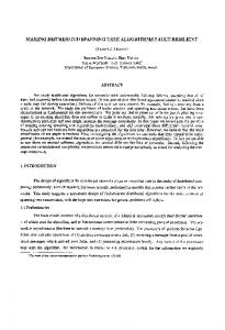
Figure 1. The Logical level of a DST The Fig. 1 is an example of the logical level of a DST. The figure represents the subjects with continuous line rectangles and the groups with dotted line rectangles. In the example, there are seventeen subjects, seven groups of level 1, three groups of level 2 and the top level group is the group � of level 3. Each group contains between two and three elements in this example. Creating groups is not enough. They must be linked together to allow communication between the groups. The following paragraphs explain how and why the groups are connected together. A group is an abstract entity made of elements. Depending on the level, an element can be a group or a subject. But an abstract entity can not affect the reality directly. So, a group can not do anything by itself. This is its elements which act for the group. For example, a basketball team can not play by itself. But players can play together for a team. To take this fact into account, each group must have at least one group representative. The representative of a group must know all the other elements to be able to send a message to the whole group. But there is no reason why an element is the representative and not the others. This is why all the elements of a group are linked together to form a clique. This way, every element can represent its group.
2.1.2
Definition
An element can be a group or a subject. Each group must have between a and b elements with 2 ≤ a ≤ 2b except the top level group which can have less than a elements. Groups of level 0 are composed of subjects and groups of level i are composed of groups of level i − 1.
2.2 2.2.1
The Interconnection Level Description
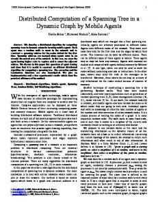
The following metaphor is interesting to understand the interconnection level of a DST. Mr McLeod lives at Edinburgh. Thus, Mr McLeod is Scottish, British, European and Human. Mr McLeod can not be the Scottish people, but he can act as a Scottish. He can also acts as a human being but can not be the humanity. Otherwise, Scotland is a province (something abstract) that can not act by itself, but a Scottish like Mr McLeod can act for Scotland. The same is true for the humanity, Mr McLeod can act for the humanity. The interconnection level of a DST follows the same principles. At the interconnection level subjects are replaced by nodes. A node can be a software, an hardware or something else which acts as a subject and as a group representative for each level. The goal of nodes is to participate together to multicast a message or to participate to a tree traversal. If the DST has h levels, each node acts as a subject, as a member of a group of level 1, ..., as a member of the group of level h. As well, any node can not be a group by itself. In the logical level section, we explained that the subjects are put together to form groups of level 1 and all of the elements of a group form a clique. To meet this hypothesis, the nodes are put together to form groups of level 1. Inside those groups of level 1, every node knows each other and form a clique. At this level, the nodes know nobody outside their own group of level 1. The Fig. 2 shows how seven nodes are linked together to form three groups of level 1.
21
212
23 211
231
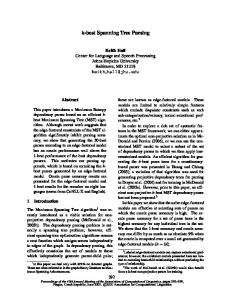
In the logical level, we also explained that the groups of level 1 are put together to form groups of level 2 and every element of the group forms a clique. To meet this second hypothesis, the groups of level 1 are put together to form groups of level 2. Every group of level 1 must know all the other groups of level 1 that are members of the same group of level 2. But how to form a clique of groups ? As explained before, a group is something abstract that can not do anything by itself. The answer is that we do not link the groups together, but we link the nodes that are members of those groups. Because, like Mr McLeod can act as a Scottish, as a British, etc., each node can act as a member of its group of level 1, of its group of level 2, ..., of the top level group. The purpose of a group is to be able to contact all of its members. By watching the Fig. 2 it is clear that every node can do it at level 1, because of the cliques. So it is enough to send a message to a node by calling it “group of level 1” to see the message send to every member of this group. So, to form a group of level 2, all the nodes of the group of level 2 have a link toward a representative of each group of level 1 of the group of level 2. A group representative is a node that can act as the group. The Fig. 3 give an example of this clique. Here, clique means that all the groups of level 1 form a clique because every node is connected to a representative of every group of level 1, which form the group of level 2. 2 21
212
23 211
231 233
213
232
222
221 22
Figure 3. Interconnections between nodes to form a group of level 2
233
213
232
222
221 22
Figure 2. Interconnections between nodes to form three groups of level 1
By watching the Fig. 3, we can see that every node can act as the group of level 2, because every node is able to send a message to a representative of the three groups of level 1. Then those three nodes send the message to the nodes of their group of level 1. This way, every node of the group of level 2 receives the message. To share the load between the nodes, it is a bad idea to have only one representative per group (Fig.4). All the work of the group will be concentrated on it. It is better that each node try to choose a different representative for each group
like shown by the Fig. 3. This way, each node shares the load of the groups. 2 21
23 211
231 233
213
212
2.2.2
Definition (continuation)
If a DST has h levels, each node must be able to be the representative of itself and its groups for each level. To be able to be the representative of a group of level i, a node must know at least one node of each group of level i − 1 which form the group of level i. A node must always choose itself as representative of its own groups.
232
2.3 The Physical Level 222
221 22
Figure 4. A badly balanced group of level 2 It is also possible to form a group of level 3 by putting together groups of level 2 with the same method. The only invariant is that every nodes must know a node (a representative) of each group of level 2 to be able to form a clique. Recursively, we are able to build a h levels Distributed Spanning Tree. Finally, as shown in the Fig. 3, a node always chooses itself to be the representative of its own group. This is to minimize the number of distant messages and maximize the number of local messages. We consider the cost of a local message to be negligible in term of time and processing cost. So, only the distant messages are count in this paper. By counting the number of distant messages, we can see that, for a n nodes DST, only n − 1 distant messages are sent to multicast the message to the n nodes. Routings tables are used to store the representatives used by each nodes. The table 1 displays the routing table of the example node 221. For each level, the routing table has a list of groups. For each group, it stores the name of the group (grp) and the name of the node (rep) that is used to represent the group. A group has at most b elements. If a DST has n nodes, it has at most dloga (n)e levels. So, the routing table can not have more than b.dloga (n)e entries and has a complexity order of O(log(n)) because a and b are constants.
Table 1. Routing tables of the node 211 level grp rep grp rep grp rep 2
1
112
2
211
3
322
1
21
211
22
222
23
231
0
211
211
212
12
213
213
The DST structure has been defined in the two previous sections. The physical level examines how the interconnection level map onto the physical links of a wired network. There are two possibilities about the network: the topology of the network is known or it is unknown. A known network can be a company or a university network and an unknown network can be the Internet. The following section studies those two cases. But most of the time a real application only knows a part of the network and knows nothing about the other. 2.3.1
Mapping on a known network
A huge network can be seen as a set of interconnected network. There are high speed local area networks which are connected to form metropolitan networks which are connected to form a world area network. A DST can take advantage of this structure to maximize the use of the local area networks communication links. √ Take a DST of n nodes with h levels and x = h n the number of elements per group. Each node has x − 1 links toward the elements of its group of level 1. It has also x − 1 links toward the elements of each level (see section 2.2.2). So, in a group of level 1, there is x.(x − 1) links that connect the x nodes together. There is also xi .(x − 1) links that connect the xi nodes of a group of level i. To multicast a message from a node to the others, a message transits on x − 1 links of the n.(x − 1) possible links of the top level h. A message transits on x − 1 links of the x.(x − 1) possible links of every groups of level i. Thus, there are xh−i .(x − 1) messages that transit through the n.(x − 1) links of level i. Two remarks come from those values. If i and j are two level numbers with i > j, xi−j more messages are sent at the level j than at the level i. A link of level j has xi−j more chance to transfer a message that a link of level i. To optimize the network use, the group must take into account the topology of the network. The nodes of a local network are put together to form the groups of the lower levels. Those groups are put together following the metropolitan networks to form the groups of metropolitan levels. Finally the group of metropolitan levels are put together to form the upper groups.
With this layout, most of the messages transit inside the local area networks and a small minority of messages are sent through the world area networks. 2.3.2
Mapping on an unknown network
From this hypothesis, it is a difficult task to describe how a interconnection level structure map on a network because nothing is known about the physical structure of the network. The Internet is an example of such network because the Internet Protocol hides the physical structure of the network. On the Internet, for a defined set of host, if we increase the number of links between the hosts, we also increase the number of paths use to route the message from host to host. By increases the number of paths, we also increase the probability to use new physical links. Finally, by increasing the number of physical links used to send messages, the probability that a link becomes a bottleneck decreases. So, the following hypothesis is used: for a defined number of hosts, if the number of logical communication links between the hosts increases, there is less chance that the link becomes a bottleneck. In the next paragraphs, the graphs, trees, rings and DST are compared in term of network use. Each topology has n nodes. We count how many messages pass through each logical links to multicast a message m from a node to the n − 1 other nodes. We count how many messages are sent through each logical links of those topologies and how many messages are sent in total. The topology that send less messages than the others and that use more links than the others should have the better scalability in term of network used. A tree has n − 1 links that connect n nodes. To multicast m, n − 1 messages are needed and each link transfers one message. A ring has n links that connect n nodes. To multicast m, n − 1 messages are needed and n − 1 of n possible links transfer one message. A graph has |E| links that connect n nodes into a connected graph. To multicast m, 2.|E| messages are needed and each links transfers two messages. A DST of n nodes, h levels and x the number of elements per group. This DST has n.h.(x−1) links that connect the n nodes. The probability to use a link of the first level is much more important that the probability to use a link of the other levels. To multicast m, n − 1 messages are needed. At level 1, nx .(x − 1) links of the n.(x − 1) possible links are used. At level i, xni .(x − 1) links of the n.(x − 1) possible links are used. So, for the most loaded DST links which are the links of level 1, each link has only a probability of x1 to be used. At level i, each link has a probability of x1i to be used. We suppose that every node has the same probability to
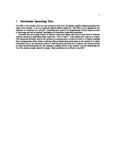
be the initiator of a multicast. We can conclude that the DST has a better scalability than the other topology in terms of network use. It sends the minimum number of messages which can be sent onto a number of links which are much more important than the other topologies. A comment can be made about this conclusion. If all the logical links use the same physical link it is useless to have lot of logical links, because the same number of messages transit through this physical links. This is true, but this worst case is unlikely to occur. The Fig. 5 display the logical links of each level of the Fig. 1 DST example. Despite the logical links are organized, the Fig. 5 suggests that there are links everywhere. So the probability to use a lot of different physical links should be hight.
Figure 5. Logical links of a DST
3
Life of a Distributed Spanning Tree
During a DST lifetime, nodes join and leave the structure. A simulator which is available [7] has been written to study the behaviors of a DST when nodes join and leave the structure. The principle of the join and leave algorithms are described in this section. There are similarities between DST and B-Trees. D. E. Knuth [11] writes: B-tree of order m is a tree that satisfies the following properties: 1. Every node has at most m children. 2. Every node, except for the root and the leaves, has at least m/2 children. 3. The root has at least 2 children (unless it is a leaf). 4. All leaves appear on the same level, and carry no information. 5. A nonleaf node with k children contains k − 1 keys. Both of them share those specifications: every node has at most b children; every node, except for the root and the
leaves, has at least a children; the root has at least two children (unless it is a leaf) and all leaves appear on the same level. This is why our algorithms are based on the B-tree algorithms.
3.1
The join algorithm
A node ni initiates the join algorithm to join a DST. To be able to join the DST, ni must know at least one member of it. We suppose that ni already knows this member node nd before executing the join algorithm. The algorithm has five steps. 1. ni asks nd to join the DST. 2. nd checks if there is enough space inside its group of level 1. If there is already b nodes in its group of level 1, the group splits into two groups of level 1. To be able to split, it must have enough space in the group of level 2 to host the new group of level 1. If not, the nd ’s group of level 2 splits in two groups as well, and so on. In the worst case, a new level must be added by splitting the top level group. At the end of the second step, there is always enough space in the group of level 1 to accept a new node. 3. nd sends to ni the list of the members of the group of level 1, the list of its representatives of the other groups for every level and the authorization to join the DST. 4. ni is added in the nd ’s group of level 1. 5. ni need to have a representative for every group of each level to be able to form a clique. ni had already got the list of the nd representatives at the third step. ni can use this list, but this way, every node uses the same set of representatives. This is against the load balancing expectations explained in section 2.2. Instead, ni asks to every nd ’s representative a reference on another representative which has the same role. If n the number of nodes which form a DST, the complexity order of splitting a group is O(n). The complexity order of adding a node if there is no need to split the group of level 1 is O(log(n)) and O(n) otherwise.
3.2
The leave algorithm
A node ni initiates the leave algorithm to leave a DST. This algorithm can be easily run by another node in case of node failure. The algorithm has three steps. 1. ni asks to every node which use ni as a representative to use another one. At the end of this step, no node depends of ni to forward any messages. To simplify this step, in our simulator, every node has a list of nodes
that use it as a representative and the new representatives are chosen by ni . 2. ni checks if there is enough nodes in its group of level 1 to be able to leave. If there is already a nodes in the group, ni merge the group of level 1 with another group of level 1 which is in the same group of level 2. If there is not enough groups in the group of level 2, ni merges two groups of level 2, and so on. In the worst case, a level is removed. 3. ni leaves its group of level 1. Merging two groups together is a little more difficult than splitting a group into two parts. If we suppose that the first group has a elements and the second has x elements with a ≤ x ≤ b, three cases appear. In the first case a + x < 2a, then the two groups must be merged in one. In the second case a + x > b, then the two groups must not be merged in one. Instead, some nodes of the bigger group are transfered to the smaller group. In the third case 2a ≤ a + x ≤ b, then the two previous actions are possible. If n is the number of nodes which form a DST, the complexity order of merging groups is O(n). The complexity order of removing a node if there is no need to merge the group of level 1 is O(log(n)) and O(n) otherwise.
4. Distributed Spanning Tree Traversals There are several algorithms to do a DST traversal. This section explains two of them. A parallel traversal to send a message m in O(log(n)) units of time and a sequential traversal which visits the nodes one by one. If a DST has n nodes, these two algorithms use respectively n − 1 and 2n − 2 distant messages. Those algorithms use these two properties of a DST: every node knows a representant of each element of its groups; a node must use itself to be the representant of its groups. For these algorithms, we suppose that the DST has n nodes and h levels, and ni is the initiator of the traversal. The local messages are considered to be transmitted instantaneously and to add no load on the network. We also suppose that the time of the distant message transmission is much more important that the processing time of a request. The presented algorithms send recursively the message hgroup of level i, mi. Each node acts as a leaf and as a representative of its group for every level. This is why the message states the name of the group that receives the message. m is the message which is multicasted.
4.1. Parallel traversal ni start the traversal by sending hgroup of level h, mi to ni . This is a local message, so it has no cost.
When a node receives a hgroup of level i, mi message with i > 0, the node send hgroup of level i − 1, mi to all of the representatives of the elements of its group of level i. If there are x elements in the group of level i, only x − 1 distant and 1 local messages are send. All of the messages are sent at the same time, so it takes one unit of time to send the messages to every element of the groups of a level. When a node receives hgroup of level 0, mi, the node does not send any messages but it can process m. This is the terminal condition of this traversal.
fied to enhance local connectivity in a hierarchical, modular fashion. The k children of every node are grouped together to form a clique. These cliques add robustness and alternate paths to the tree structure. This topology was designed to build parallel computer which combines the positive features of the tree and the hypercube. But with the HiC, all nodes are not equal. There are processor elements which are the leaves and switching elements which forward the messages. Another disadvantage of the HiC is if the root and its k children fail, the whole structure is split in k separated groups.
4.2. Sequential traversal
Q. M. Malluhi and M. A. Bayoumi [12] proposed the Hierarchical Hypercube (HHC). An n-HHC has three levels with n = 2m + m. The first level is constituted of 2n nodes. At the second level the 2n nodes are grouped into 2m hypercubes of 2m nodes called SonCubes. At the third level, the 2m SonCubes are connected in an hypercube fashion to form a father cube. Each SonCube has exactly 2m links that connect it to the other SonCubes, and each link is incident to one node of the SonCubes. This is interesting because every node has the same role. It also share with the DST a common vision: it uses recursively, a distributed structure to add several levels and is able to keep a degree for each node with a complexity order of O(log(n)). But the HHC was designed to build parallel computers and not to build distributed systems. So it has a low degree for each node and need a static number of nodes. It is also a very static structure where it is difficult to remove or to add a node.
ni start the traversal by sending hgroup of level h, mi to ni . This is a local message, so it is considered that it has no cost. Then, ni waits for the result. When a node receives a hgroup of level i, mi message with i > 0, it sends hgroup of level i − 1, mi to itself and waits for the result. After, for each representative of the elements of the group of level i, if the representative is not the node itself, it sends to the representative the message hgroup of level i − 1, mi and waits for the result. This loop is done sequentially, waiting for the result before sending the next message. Finally it sends the result to the node which has sent the hgroup of level i, mi message. If there are x elements in the group of level i, 2 local and 2x − 2 distant messages are sent. Some uses of sequential tree traversal stop the traversal before visiting every node. For example, this happend when a particular node is found. This is why this algorithm gives the priority to the local messages. If the elements of the lower levels groups are linked through local network as explained in the section 2.3.1, going down first through the local node gives the opportunity to visite the node of the local area network before the others. Finally, when a node receives hgroup of level 0, mi message, the node processes m and returns the result to the node which sent the message.
5
Related Work
The Distributed Spanning Tree is not the first structure which try to interconnect a set of nodes efficiently. Well known structures like hypercubes or fat-trees was studied extensively and are used to build parallel computer. Other structures like the Distributed Hash Tables are interesting because they are organized, completely distributed and specifically designed to build distributed systems. Finally, other algorithms are able to send a message to every node and share the load between them, without any strict organization. S. Campbell, M. Kumar and S. Olariu [2] proposed the hierarchical cliques (HiC). The HiC is a k-ary tree, modi-
S. D. Gribble et al. [9] introduced a data structure (DDS) with a Distributed Hash Tables (DHT). The DHT provides incremental scalability of throughput and data capacity as more nodes are added to the cluster. To achieve this, they horizontally partition tables to spread operations and data across bricks. The DDS was used to build a large scale file service. After the DHT become a peer-to-peer system, gaining more scalability. Chord and Pastry are two implementations of DHT. A. Rowstron and P. Druschel [16] explains that Pastry bear some similarity to the work by Plaxton et al. [15]. In the Plaxon structure, each object has a unique address x of n bits. The structure uses the address prefix to route the message to the object. Each node has a routing table of nb levels. Each node has at the ith level of the routing table, a list of links with the following constraints: the (i−1).b bits prefix of the pointed nodes must be the same as the current node, for the 2b permutations of the i.b bits prefixes with the same (i − 1).b bits prefix, two nodes (for fault tolerance) are pointed by the routing table. At most, nb hops are needed to route a message to an object with this structure. The approach of routing based on address prefixes can be viewed as a generalization of hypercube routing. Pastry with its ring topology and its traversal links appears less complex and more flexible. I. Stoica et al. [17] explains that Chord, on the other hand, is substantially less complicated
and handles concurrent node joins and failures well. The DHT are interesting because every node is able to send a message to any other nodes in only O(log(n)) hops. They also need only O(log(n)) entries in their routing table. Finally, they are theorically scalable, resistant to failures and the load is equally balanced between nodes. Those properties are common with the Distributed Spanning Tree. But their use is completely different. The DST are able to send efficiently one to all messages, the DHT are able to send efficiently one to one messages. Research have been made to use DHT topology to build multicast tree. M. Castro et al. [3] describe Scribe as a scalable application-level multicast infrastructure. Scribe creates a multicast tree, rooted at a rendez-vous point, to disseminate the multicast messages in the group. The multicast tree is created using a scheme similar to reverse path forwarding. The tree is formed by joining the Pastry routes from each group member to the rendez-vous point. Druschel et al. [4] explain that Scribe can be used to build cooperative multicast environments called SplitStream. The key idea in SplitStream is to split the content into k stripes and to multicast each stripe using a separate tree. The challenge is to construct this forest of multicast trees such that an interior node in one tree is a leaf node in all the remaining trees. All the interior nodes that look for new children register in a Scribe multicast group. When a new node arrives, it sends a message to the Scribe groups and contact k interior nodes to join the k trees. When an interior node has the desired number of children, it leaves the Scribe group. With SplitStream, every node is an interior node for only one tree. So, the load is equally distributed between the participating nodes. But SplitStream is one source only multicast structure and all the data must be send from a unique set of nodes. Some peer-to-peer system use less structured topology and use best effort algorithm. The Gnutella specification [5] explains that a Gnutella servent connects itself to the network by establishing a connection with another servent currently on the network. The acquisition of another servent’s address is not part of the protocol definition. So the topology is a connected graph without more specification. In such topology, search and multicast are done by flooding. Despite the high bandwidth consumption of the flooding, the structure is strong against faults and the algorithms that add or remove a node are straightforward. The Kazaa networks allow to pass an additional scale by the use of supernodes [14]. Nodes elect supernodes to represent themselves. The discovery is done between supernodes and the other nodes are not longer queried by the discovery process. It results a reduction of messages. JXTA [1] also used a similar methods, although supernodes are called rendez-vous peers. JXTA also adds a cache mechanism to achieve better performances. Finally, the supernodes method has been chosen to implement the discovery mechanism of the Distributed
Integrated Engineering Toolbox (DIET) [8]. Initially, the DST has been studied to build a scalable discovery service for DIET which is a RPC-GRID middleware based on the Application Service Provider architecture. Few systems try to share the communication load between the peers like SplitStream and BitTorrent. B. Cohen [6] introduces BitTorrent as a file distribution system with pareto efficiency. A BitTorrent platform is composed of a tracker and peers. The tracker is a directory with the reference of all the peers which replicate a file. With the help of the tracker, each peer connect itself with twenty or forty other peers. Peers exchange pieces of the data with a “tit-for-tat” policy. This system uses a simple best effort algorithm and are able to achieve good performance and scalability by sharing the load between the peers efficiently. M. Izal et al. [10] conclude that the performance achieved, in terms of the throughput per client during download and the ability to sustain high flash-crowd, demonstrate that BitTorrent is highly effective. Unfortunately, its latency is high and BitTorrent can not be used to send a stream in realtime.
6
Conclusion
In this paper, a novel structure which support efficiently the traversal of its elements has been presented. The trees are organized into a hierarchy by having a hierarchy of nodes. By contrast, the Distributed Spanning Trees are organized into groups where all the nodes have the same responsibilities. The hierarchy is accomplished by making groups of groups. As a result, the Distributed Spanning Tree has the same properties than the usual trees but without the bottlenecks. This means, for a n nodes DST, the possibility to multicast a message in O(log(n)) unit of time with n − 1 messages and the possibility to traverse sequentially the n nodes in 2n − 2 messages. There is a small amount of the structure knowledge in each node with a complexity order of O(log(n)). The group organization involves the whole set of nodes, so the load is mostly balanced between the nodes. Then, the bottleneck caused by the usual tree structure does not exist with the DST. However, the Distributed Spanning Tree is a new structure which need more studies to be completely known.
References [1] JXTA v2.0 protocols specification, 2004. [2] S. Campbell, M. Kumar, and S. Olariu. The hierarchical cliques interconnection network. Elsevier J. Parallel Distrib. Comput., 64:16–28, Jan. 2004. [3] M. Castro, P. Druschel, A. Kermarrec, and A. Rowstron. SCRIBE: A large-scale and decentralized application-level
[4]
[5] [6] [7]
[8]
[9]
[10]
[11]
[12]
[13]
[14] [15]
[16]
[17]
multicast infrastructure. IEEE J. Select. Areas Commun., 20(8), Oct. 2002. Special Issue on Network Support for Multicast Communications. M. Castro, P. Druschel, A.-M. Kermarrec, A. Nandi, A. Rowstron, and A. Singh. SplitStream: High-bandwidth content distribution in cooperative environments. In Proc. of the 2nd International Workshop on Peer-to-peer System, Berkeley, CA, Feb. 2003. Clip2. The gnutella protocol specification v0.4, 2001. B. Cohen. Incentives build robustness in bittorrent, 2003. S. Dahan. A distributed spanning tree simulator, 2004. http://lifc.univ-fcomte.fr/˜dahan/ dst/gp2pc-dst-sim.tar.gz. S. Dahan, J. Nicod, and L. Philippe. Scalability in a GRID server discovery mechanism. In 10th IEEE Int. Workshop on Future Trends of Distributed Computing Systems, FTDCS 2004, pages 46–51, Suzhou, China, May 2004. IEEE Press. S. Gribble, E. Brewer, J. Hellerstein, and D. Culler. Scalable, distributed data structures for internet service construction. In Symp. OSDI 2000, 2000. M. Izal, G. Urvoy-Keller, E. Biersack, P. Felber, A. Al Hamra, and L. Garc´es-Erice. Dissecting bittorrent: Five months in a torrent’s lifetime. In Passive and Act. Net. Meas., 5th In. Wk., volume 3015 of LNCS, pages 1–11, Antibes Juan-les-Pins, France, Apr. 2004. D. E. Knuth. The Art of Computer Programming, volume 3, chapter 6.2.4. Addison-Wesley, 75 Arlington Street, Suite 300, Boston, MA 02116, 1998. Q. M. Malluhi and M. A. Bayoumi. The hierarchical hypercube: A new interconnection topology for massively parallel systems. IEEE Trans. Parallel Distrib. Syst., 5(1):17–30, Jan. 1994. R. E. McGrath. Discovery and its discontents: Discovery protocols for ubiquitous computing. Technical Report UIUCDCS-R-99-2132, Department of Computer Science University of Illinois, Champaign, IL, USA, Apr. 2000. S. Networks. The glossary: Supernodes, 2004. C. G. Plaxton, R. Rajaraman, and A. W. Richa. Accessing nearby copies of replicated objects in a distributed environment. In ACM Symp. on Parallel Algo. and Arch., pages 311–320, 1997. A. Rowstron and P. Druschel. Pastry: Scalable, decentralized object location, and routing for large-scale peer-to-peer systems. LNCS, 2218:329–350, 2001. I. Stoica, R. Morris, D. Liben-Nowell, D. R. Karger, M. F. Kaashoek, F. Dabek, and H. Ballakrishnan. Chord, a scalable peer-to-peer lookup protocol for internet applications. IEEE/ACM Trans. Networking, to appear.