The automated system, including the vision system, the 3-axis motor, the universal jamming gripper, the air fluidized bed and the tilting actuators. (B).
The dynamics of legged locomotion in heterogeneous terrain: universality in scattering and sensitivity to initial conditions Feifei Qian and Daniel I. Goldman Georgia Institute of Technology Atlanta, Georgia 30332–0250 Abstract—Natural substrates are often composed of particulates of varying size, from fine sand to pebbles and boulders. Robot locomotion on such heterogeneous substrates is complicated in part due to large force and kinematic fluctuations introduced by heterogeneities. To systematically explore how heterogeneity affects locomotion, we study the movement of a hexapedal robot (15 cm, 150 g) in a trackway filled with ∼ 1 mm “sand”, with a larger convex “boulder” of various shape and roughness embedded within. We investigate how the presence of the boulder affects the robot’s trajectory. To do so we develop a fully-automated terrain creation system, the SCATTER (Systematic Creation of Arbitrary Terrain and Testing of Exploratory Robots), to control the initial conditions of the substrate, including sand compaction, boulder distribution, and substrate inclination. Analysis of the robot’s trajectory indicates that the interaction with a boulder can be modeled as a scatterer with attractive and repulsive features. Depending on the contact position on the boulder, the robot will be scattered to different directions after the interaction. The trajectory of an individual interaction depends sensitively on the initial conditions, but remarkably this dependence of scattering angle upon initial contact location is universal over a wide range of boulder properties. For a larger heterogeneous field with multiple “scatterers”, the trajectory of the robot can be estimated using a superposition of the scattering angles from each scatterer. This scattering superposition can be applied to a variety of complex terrains, including heterogeneities of different geometry, orientation, and texture. Our results can aid in development of both deterministic and statistical descriptions of robot locomotion, control and path planning in complex terrain.
I. I NTRODUCTION Rocky, loose substrates are common in environments that exploratory robots must traverse; such terrains can contain granular media (GM) with particle sizes spanning many orders of magnitude. When robotic locomotors travel across these “flowable” types of heterogeneous terrain, they exhibit characteristic failure modes (slips, unstable foot-holds, impassable barriers, course deviations, or limb/tread fluidization of a thin layer of smaller particles) which significantly affect robot stability, maneuverability and power consumption. One of the major challenges in creating the next generation of mobile robots is expanding the scope of terramechanics [1][2] from large tracked and treaded vehicles on homogeneous ground to arbitrarily shaped and actuated locomotors moving on and within complex heterogeneous terrestrial substrates, to create a “terradynamics” [3] (in analogy to hydro and aerodynamics
which provide predictive power for aquatic and aerial vehicles) of locomotion on heterogeneous ground. However, in typical heterogeneous environments, the force fluctuations introduced by heterogeneities (gravels, rocks, boulders, etc.) during intrusion and drag can be large, which makes the applicability of continuum terramechanics [1][2] unclear. Currently, most terrestrial vehicles (including mobile robots) are tested on substrates made of standardized homogenous media (e.g. Ottowa sand [4], lunar simulants [5]), while robot locomotion on heterogeneous granular ground is relatively unexplored. Modelling and controlling robot locomotion on heterogeneous granular terrain requires fundamental understanding of the complex interactions between the robot and the ground. This interaction can be especially complicated when obstacles possess mobility relative to the substrate underneath (e.g., boulders/rocks can rotate, tilt, shift on or even sink into the fine sand). Multiple types of interactions – robot with the fine sand [3], robot with the multi-shaped boulders/rocks, as well as boulders/rocks with the fine sand – must be considered, and the mobility of the boulders/rocks can dynamically change the terrain profile during the interaction. Studying the response of a locomotor on heterogeneous granular terrain will generate a better understanding of such interactions, and this understanding can provide a predictive guidance in navigation planning. Most traditional navigation planning methods involve finding a collision free path, which requires the robot to avoid obstacles. For example, the potential field method (PFM) [6] treats obstacles as repulsive potentials that repel the robot. This is legitimate for most wheeled/treaded robots which must circumvent obstacles, but for legged robots, traversing obstacles by stepping over or upon them [7] can be another option. Allowing robots to interact with obstacles [8], or even manipulate the locomotion environment [9], could significantly expand viable exploration space for obstaclefilled environments. Such advances in robot mobility will also require a statistical terradynamics framework for locomotion and control, in which deterministic understanding of robot-heterogeneity interactions can be used as inputs. A statistical terradynamics will allow robots to evaluate obstacle traversability and predict the probability of outcomes
(e.g., possible failure, trajectory deviation, etc.) of different locomotion modes. In this manner robots could choose locomotion maneuvers to traverse challenging terrain, or perform successful anticipatory control [10] before the disturbance to avoid fatal failure and course deviation. To begin to create a terradynamic framework for legged robot locomotion on heterogeneous flowable substrates, we previously designed and constructed a SCATTER system [11] (Systematic Creation of Arbitrary Terrain and Testing of Exploratory Robots) to automatically create heterogeneous granular ground conditions and perform robot locomotion tests. In this paper we use SCATTER to study the robot’s locomotion on a diversity of heterogeneities, searching for principles that will allow us to move toward a terradynamics of heterogeneous granular media. We find that the complex interaction between the robot and a single boulder can be modelled as a scattering process – each interaction will cause the robot to leave the boulder with a certain angle of trajectory deviation, as if the robot was scattered. The form of the scattering process is sensitive to initial conditions of the robot but is insensitive to boulder shape and texture. As an initial step toward the heterogeneous terradynamics, we largely focus on single localized scatterers, but discuss toward the end of the paper the applicability of these results to robot locomotion on more complex heterogeneous fields with arrays of scatterers.
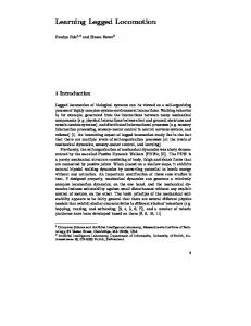
The central structure of the SCATTER system consists of a 122 cm long, 51 cm wide air fluidized bed trackway (Figure 1B). Four vacuums (RIDGID, 16 gallon) are connected below the trackway, forcing air through a flow distributer (0.635 cm thick, 50 µm pore size porous plastic) to evenly fluidize the fine grains in the trackway, allowing control of the compaction and creation of repeatable homogeneous granular states of the fine grains. We used 1 mm diameter poppy seeds as the model fine grains in this study, but this ground stiffness control technique can be applied to a large variety of granular media, with particle diameter ranging from hundreds of microns to a few millimeters. The resistance of the granular substrate created using this method is highly repeatable, and could be varied over a large range, from greater than that of close packed compaction states [12] to a zero resistance state [13]. Also, as previously measured in intrusion tests, the results obtained using these model granular substrates can be applied to more complex natural granular media composed of grains with greater polydispersity and angularity [3]. The entire trackway is supported by an aluminum tiltable support framing actuated by two linear actuators (Firgelli, 454 kg load, 61 cm stroke) such that the trackway can tilt to create inclined/declined granular environments. By controlling the extruded length of the linear actuator, the substrate inclination angle could be varied to more than 40◦ , exceeding the maximum angle of stability [14] for most granular media used in locomotion studies [15][3].
II. S YSTEMATIC C REATION OF A RBITRARY T ERRAIN AND AUTOMATED T ESTING OF ROBOT L OCOMOTION Natural heterogeneous granular terrains vary in particle size, shape, compaction, orientation, etc., making exhaustive testing of all terrain types impossible. In our study, we use a model substrate – a bi-dispersed granular test bed filled with ∼ 1 mm diameter poppy seeds (the simplified “sand”) with larger particles (the simplified “boulders”) of various shapes embedded within – to control and vary terrain parameters. The relatively simple geometry and configuration of the model terrain makes it feasible to create repeatable states of granular media with controlled heterogeneity, and facilitates a systematic exploration of heterogeneous ground properties.
(B)
(A)
servo
(C) vacuum tubing Air filter Gripper
To precisely control terrain parameters, and to systematically investigate robot locomotion on a variety of heterogeneous granular terrains, we previously developed a fully-automated terrain creation which we call Systematic Creation of Arbitrary Terrain and Testing of Exploratory Robots (SCATTER [11], Figure 1A) apparatus. Using SCATTER, properties of heterogeneous multi-component substrates such as compaction, orientation, obstacle shape/size/distribution, and obstacle mobility within the substrate, can be precisely controlled and varied to emulate a wide range of natural terrain properties.
Hall-effect sensor
(D)
C-legs
1 cm
Automated terrain creation and locomotion testing system. (A) Fig. 1. The automated system, including the vision system, the 3-axis motor, the universal jamming gripper, the air fluidized bed and the tilting actuators. (B) Mechanical drawing of the automated system: a 3-axis motor mounted on a tiltable trackway. (C) The universal jamming gripper lifting the robot. (D) The model locomotor, a small hexapedal robot (15 cm, 150 g).
To generate states of arbitrary heterogeneity, a 3-axis motor system (Copley, STA25, STB25, XTB38) was installed above the trackway, enabling the motor end-effector to move in three dimensions. The motor end-effector drives a universal jamming gripper [16] (Figure 1C) to programmed locations, allowing for the creation of arbitrary distributions of boulders. The customized gripper assembly includes a balloon filled with granular material (a “universal jamming gripper” [16]), a support frame, and a HI-TEC servo motor (HSR-5980SG). The 3D-printed support frame connects the gripper to vacuum tubing through an air filter, enabling the granular material in the gripper balloon to switch between fluid-like and solid-like properties. The fluid-like property of the granular media inside the balloon (when suction is off) allows the gripper to deform around the robot or boulders, while the solid property of the granular material (when suction is applied) enables the gripper to reach a jammed state, resulting in a rapid gripping of objects of complex shapes.
speed reference videos that synchronized with the tracking data.
The gripper can grasp objects with large variation in geometries (spheres, polyhedrons, cylinders, etc.), sizes (as long as the gripper membrane can reach sufficiently around the sides of the target [16], ≈ 50% ± 20% balloon diameter), and weights (up to 0.2 kg for the size of our gripper). Using the universal jamming gripper, a large variety of ground heterogeneities (boulders, rocks, logs, etc.) as well as small scale robots can be automatically distributed and retrieved to produce different heterogeneous ground configurations and locomotor initial conditions. The gripper support frame also provides an attachment from the gripper balloon to the servo disk, enabling the gripper assembly to adjust the orientation of the boulder and the robot for each test.
Previous studies revealed that even on simplified bi-disperse heterogeneous granular ground robot locomotion exhibited chaotic dynamics and multiple robot-ground interaction modes [11]. The robot could slip on the top of a deeply buried boulder, push a lightweight boulder to yield towards the side or into the sand, become stuck on the top of a large boulder, or force a high-friction boulder to rotate in place. The complexity of the observed interactions, even in the simplified substrates, prompted us to concentrate on an even simpler model system. Therefore we began with a single boulder interaction study to systematically analyze how different boulder properties and robot kinematics affected robot-boulder interaction modes and robot locomotion performance.
We used a small hexapedal robot (15 cm, 150 g, Figure 1D) as a simplified model locomotor to perform laboratory experiments. The robot has six 3D-printed Cshaped legs and uses a bio-inspired alternating tripod gait. The gait frequency of the robot was controlled by a DC motor (Micromo 1724-SR with IE2-1024 encoder) using pulse width modulation (PWM). A Hall-effect sensor was attached on the robot body to control the initial leg phase and to track leg tip positions during the run. We use this small RHex-like [17] robot as a model locomotor to perform systematic study with variation in leg shape, leg roughness, gait frequency, etc., and to discover interaction principles that can be further expanded to other legged locomotors. Kinematic information of the robot, including the x, y, z center of mass (CoM) position as well as the yaw, pitch, and roll angle, was obtained by tracking three IR-reflective markers attached to the robot using three top-view cameras (Naturalpoint, Flex13, 120 FPS). The cameras also monitored the location of the robot and the boulders before and after each test. This information was communicated to the motor system, so that the gripper could retrieve both the robot and boulders. The system also recorded dorsal and lateral high
All functions of the SCATTER system were controlled by a single integrated LabVIEW program. The system can currently perform more than 200 locomotion tests in one day, without human intervention, allowing comprehensive and systematic exploration of effects of arbitrary heterogeneity and spatial distribution on interaction modes and performance. Using this system, we can investigate a variety of terrain and locomotor parameters, including sand resistance, boulder geometry/texture/orientation, heterogeneity distribution, substrate inclination, as well as robot leg shape, foot size and gait frequency, etc.. We first discuss robot locomotion during interaction with a single boulder, and then extend this to large, multi-boulder fields. III. S INGLE BOULDER INTERACTION ANALYSIS
A. Experimental setup We analyzed the interaction between the robot and a single boulder buried in the sand, and the resulting robot CoM trajectories. The boulder size was chosen to be 4 − 5 cm in diameter, comparable with robot C-leg diameter (3 − 4 cm), such that the boulder had a significant effect on robot locomotion and had enough exposed area to distinguish legboulder contact positions, but was not a barrier too high for the robot to traverse. We tested robot interactions for different boulder properties varying boulder shape, orientation, and texture. We also tested robot interactions with both immobile boulders (i.e., the boulder was fixed at a certain burial depth) and free boulders (i.e., the boulder was allowed to move during interaction). In all experiments, robot leg frequencies were small (< 0.3 Hz) so that the inertial effects were negligible. At the beginning of each test, the gripper placed the robot at a different initial position relative to the boulder (Figure 2A). The fore-aft initial position (along the Y axis) of the robot was programmed to be within 1 − 2 bodylengths away from the
v
(A)
automated system performed a check on the robot’s initial X and Y position as well as initial yaw angle, and re-positioned the robot if the error was larger than the pre-set threshold (position error > 1 cm and heading error > 2◦ ).
Y Lateral initial position
X Fore-aft initial position
B. CoM trajectory analysis for a spherical boulder
(B)
v
Boulder
Fore-aft initial position (cm)
θ
(C)
X (cm)
−10
v Boulder
0
10
-20
0 Y (cm)
Lateral Initial position (cm)
5 cm
5
0
-5
20 15
10
20
Fig. 2. Single boulder scattering experiment. (A) Experimental setup. The center of the boulder is set as the origin. X and Y axis represents lateral and fore-aft direction. (B) Robot CoM trajectories for different lateral initial positions (i.e., different impact parameter). Data were collected from a free boulder experiment, where the boulder was initially placed at a burial depth of ≈ 1 cm, a quarter of the free boulder diameter. Trajectory color indicates different impact parameters. (C) Robot CoM trajectories for different foreaft initial positions (i.e., different leg phase at contact). Data were collected from immobile boulder experiment, where the boulder was fixed at a burial depth of ≈ 1.25 cm, a quarter of the immobile boulder diameter. Red lines represents the linear fit of the robot’s trajectories after boulder interaction, which was used to calculate the scattering angle θ. The white circles in (B) and (C) indicate boulder position.
boulder, and increased by 1 cm increments each trial. After interaction with the boulder, the robot was programmed to continue moving for another 1 − 3 bodylengths. This allowed accurate characterization of the robot’s CoM trajectory angle after the disturbance. Similarly, the lateral initial position of the robot’s CoM (along the X axis) was varied within 0 − 9 cm, with 0 cm being robot centerline passing the boulder center and 9 cm being the robot no longer in contact with the boulder along its trajectory. We define this lateral distance between the boulder center and the robot centerline as the “impact parameter”, in analogy to scattering theory in particle physics [18]. After the gripper placed the robot, the
We collected ∼ 1000 runs for a spherical boulder using the automated system, varying the robot’s initial lateral and fore-aft positions. Figure 2B shows ∼ 200 trajectories with robot lateral initial positions (the impact parameter) varied from −4 cm to 4 cm relative to a 4 cm diameter spherical boulder. All trajectories were plotted in the boulder frame (i.e., with the boulder located at the origin (0, 0)). The colors of the trajectories represent different impact parameters. We observed that the robot’s trajectories were straight before the interaction with the boulder, then exited to different angles (depending on the initial conditions) after the interaction. Surprisingly, we noticed that for a significant number of runs, instead of being repelled by a repulsive obstacle potential as assumed in the PFM, the robot turned towards the boulder after the interaction, as if it was attracted to the boulder. Closer analysis revealed that the interactions with the single boulder could be modelled using attractive or repulsive scattering angles depending on the initial conditions. For each robot CoM trajectory, we fit straight lines before and after the boulder interaction, to characterize the trajectory angle change (the scattering angle, θ). The analogy to the scattering problem simplified the complex interaction, allowed systematic characterization of the effect of different boulder properties on robot trajectory deviation, and allowed the extension of the single boulder result to large, multi-scatter fields. Figure 2C shows CoM trajectories with variation in initial fore-aft positions. The impact parameter was fixed, and the robot was programmed to start from each initial position with the same initial leg phase such that the leg contacted with the boulder at different leg phases. We noticed that the scattering angle depended sensitively on the initial fore-aft position, and this sensitive dependence was highly repeatable given the same initial fore-aft position. The sensitivity of robot trajectory to the initial conditions indicates that the effect of a given boulder on robot trajectory deviation can be expressed by a 2D scattering pattern with the X and Y axes representing the leg phase and impact parameter effect, respectively (Figure 3d). We investigate this scattering pattern for boulders of different properties, and search for a general principle that governs the robot-boulder interaction modes.
30 15
γ 0
Scattering angle (º)
(d)
(a)
20
(g)
10 0 −10
(c)
(e)
15 0 -15
(f)
30 15 0 -15
0
10
100
150
200
250
(h)
0 −10
20
(i)
10 0 −10
R
Leg phase effect
50
zone angle γ (°) Scattering angle (º)
30
Scattering angle (º)
(b)
Impact parameter effect
-15
RF
F
LF
L
LB
T
Contact zone
Fig. 3. Scattering pattern and scattering angle dependence on contact position for boulders of different shapes and orientations. (a, b, c) Top view diagrams of the three boulders, including a sphere (a), a 90 degree oriented rhombicuboctohedron (b), and a 45 degree oriented rhombicuboctohedron (c). Different colors (yellow, cyan, purple, green, blue, red, black) corresponding to different contact zones (right, right-front, front, left-front, left, left-back, top), respectively. Among all the zones, it was relatively unlikely for the robot leg to struck on the B and RB zones due to the leg rotation direction and the experiment configuration (i.e., all tests were performed with robot initial lateral position on the left side of the boulder, since the scattering pattern was symmetric for both sides). Therefore statistical data were not compared for these three zones, and were only analyzed and plotted for a selective of boulders in Figure 4. For the 90 degree oriented rhombicuboctohedron (b) and the 45 degree oriented rhombicuboctohedron (c), the zones were divided using the edges of the polyhedrons; whereas for the sphere (a), the zones were divided based on the radius r and zone angle γ (right: −20◦ < γ < 20◦ , r > 2 cm; right-front: 20◦ < γ < 60◦ , r > 2 cm; front: 60◦ < γ < 100◦ , r > 2 cm; left-front: 100◦ < γ < 130◦ , r > 2 cm; left: 130◦ < γ < 170◦ , r > 2 cm; left-back: γ > 170◦ , r > 2 cm; Top: r < 2 cm. (d, e, f) 2D scattering pattern for 3 different boulders. The X and Y axes represent different robot fore-aft initial positions (i.e., the leg phase effect) and lateral initial positions (i.e., impact parameter effect), respectively. (g, h, i) Scattering angle vs. contact zone for three low-friction boulders. Lower and upper limit of the central box in boxplots (h, i) represent the 25% and 75% quantile of the data, respectively. Markers color convention in (g, h, i) is the same as (a, b, c). Marker shape (square, diamond, circle) represents front, middle, rear leg contacted with the boulder, respectively. Markers without outlines indicate robot leg shaft contact.
C. Robot scattering pattern for different boulder shape, orientation and roughness To investigate how different boulder properties affected the scattering pattern, we studied the robot’s interaction with boulders of different shapes, orientations and roughnesses. Boulder shapes were varied through 3D-printing (uPrint SE plus, Stratasys), and boulder roughness was varied by coating the boulder surface with different textures. We note that natural heterogeneous terrain comes in a huge variety of forms and it is obviously impossible to test all possible boulder configurations. In this study, as a starting point to initiate an effort in creating a terradynamics framework for legged robot locomotion on heterogeneous granular substrates, we used boulders with regular geometry like spheres and symmetric polyhedrons to simplify the interaction and facilitate the development of initial principles. However, we seek to develop key principles which are not limited to these select cases but can be expanded to a generalized form to provide a better understanding of the robot-heterogeneity interaction and its effect on locomotor performance. We first tested and analyzed the scattering pattern for three low-friction boulders, including a 5 cm diameter glass sphere, a 3D printed 90 degree oriented 5.2 cm diameter ABS plastic rhombicuboctohedron, and a 3D printed 45 degree oriented 5.2 cm diameter ABS plastic rhombicuboctohedron
(Figure 3a, b, c). The rhombicuboctohedron was chosen because its polyhedral faces were naturally separated into 9 zones – front (F), back (B), left (L), right (R), right-front (RF), left-front (LF), right-back (RB), left-back (LB) and top (T), which facilitated identification and analysis of the effect of leg-boulder contact positions. The spherical boulder, on the other hand, was chosen as the simplest example of a continuously varying boulder surface inclination angle, while the symmetric shape facilitated the interaction analysis and the generalization of our principles. We observed that the scattering pattern exhibited similar characteristics for all three boulders (Figure 3d, e, f). The scattering angle varied sensitively along the fore-aft direction (between 30◦ and −15◦ ) but was relatively uniform along the lateral direction. To explain this phenomenon we characterized the leg-boulder contact positions on the boulder using different contact zones. For the polyhedral boulders, we used the polyhedron faces to categorize the contact zones (Figure 3b,c), whereas for the spherical boulder, we used a polar coordinate system (the radial distance r and the zone angle γ) to describe the contact position on the boulder (Figure 3a). We analyzed the scattering angle dependence on contact zone for high-friction boulders as well (Figure 4) by coating the boulder surface with 120 grit sandpaper.
4
(A)
20
Scattering angle (º)
scattering angle (º)
3
2
1
30 20 10 0
10
0
−10
−10
−80 234 1234
Right
Right front
1234 1234
Front
Left front
1234
1234
Left
Left back
1234 1 3 4 13
Top
(B)
−40
0
40
Boulder surface inclination at contact (º)
80
Back Right back
Contact zone Fig. 4. Scattering angle vs. contact zone for four boulders with differences in roughness and orientation, including a rough 45 degree oriented rhombicuboctohedron (1), a smooth 45 degree oriented rhombicuboctohedron (2), a rough 90 degree oriented rhombicuboctohedron (3), and a smooth 90 degree oriented rhombicuboctohedron (4). Colored groups represent different contact zones, and color convention is the same as in Figure 3b,c.
We found that despite variation in boulder shape (sphere vs. rhombicuboctohedron), orientation (45 ◦ shift) and roughness (low friction vs. high friction), the scattering angle vs. contact zone exhibited qualitatively similar dependence for all boulder types tested (Figure 3g, h, i; Figure 4). This universality of scattering angle dependence upon contact zone explained the similarity observed in the scattering pattern for different boulder shapes and orientation (Figure 3d, e, f), and suggests that the scattering angle can be modelled as a function of the boulder surface inclination angle at the contact point. More interestingly, we noticed that most of the “attractive” zones were distributed on the front side of the boulder (RF, F, LF), whereas most of the “repulsive” zones were distributed on the center or back side of the boulder (LB, T, RB). We hypothesized that the fore-aft direction boulder surface inclination angle was largely responsible for the variation in the scattering angle. This also explains the more significant variation of scattering angle along the fore-aft direction as compared to the lateral direction (Figure 3d, e, f).
IV. S CATTERING ANGLE DEPENDENCE ON SURFACE INCLINATION AT CONTACT
To test our hypothesis of scattering angle dependence on boulder inclination, we characterized the fore-aft direction boulder surface inclination angle at the beginning of each leg-boulder interaction for a previous experiment [11] of robot locomotion on a 2 × 4 lattice boulder field. We found that, as hypothesized, the scattering angle depended sensitively on the fore-aft inclination (Fig. 5A), and this scattering angle vs. fore-aft inclination curve was closely related to the different interaction modes (Fig. 5B):
Forced sliding (straight)
Slipping (attractive)
Forced intrusion Slipping (straight) (repulsive)
Scattering angle dependence on boulder inclination and the Fig. 5. corresponding locomotion modes for different region. (A) Scattering angle of each leg-boulder interaction as a function of the fore-aft direction boulder surace inclination angle at the beginning of leg-boulder contact. Scattering angles were characterzied from robot locomotion experiment on a lattice boulder field, with eight 2.54 cm free boulder embedded in 3 mm glass beads. All boulders were free to move during the interaction. (B) Diagram of four different leg-boulder interaction modes observed in robot locomotion test in substrate with multiple, free boulders. Different color blocks of interaction modes corresponded to the same color shaded regions in (A).
a) Inclination < −40 ◦ or > 30 ◦ (Fig. 5A, green shaded region): forced sliding mode (Fig. 5B, green shaded block), where the leg struck on the side of boulder, propelling the boulder forward or sideways. The effect of this interaction on robot performance and trajectory was small (scattering angle ≤ 5 ◦ ). b) −40 ◦ < Inclination < −15 ◦ (Fig. 5A, pink shaded region): attractive slipping mode (Fig. 5B, pink shaded block), where the leg impacted near the top of the boulder and slid down towards the front of the boulder, causing the robot to turn toward the boulder, while the boulder remained still. Robot trajectory was significantly affected in this mode (scattering angle 5 ◦ ∼ 20 ◦ ). c) −15 ◦ < Inclination < 5 ◦ (Fig. 5A, yellow shaded region): forced intrusion mode (Fig. 5B, yellow shaded block), where the robot leg struck on top of boulder, forcing the boulder downward into the fine grains. The robot exhibited a passive stability when the leg impacted on this top region of the boulder, and the effect of this interaction on robot trajectory was relatively small (scattering angle normally within ±5 ◦ ). In mode a) and c), the robot reduced the impulse of the collision by taking advantage of the mobility of boulders relative to the sand. d) 5 ◦ < Inclination < 30 ◦ (Fig. 5A, blue shaded region): repulsive slipping mode (Fig. 5B, blue shaded block), where
the leg hit beyond the top of a deeply buried boulder and slid down towards the back of the boulder, causing the robot to turn away from the boulder, while the boulder remained still. Robot trajectory was significantly affected in this mode (scattering angle −5 ◦ ∼ −15 ◦ ), similar to the attractive slipping mode. We also characterized the scattering angle vs. inclination for different boulder sizes, textures and mobilities, and found that the scattering angle vs. boulder inclination curves exhibited qualitatively similar characteristics among a variety of boulder properties. This universality in scattering angle dependence upon surface inclination of the heterogeneity allows us to further generalize our results to ground heterogeneities with different geometries, and in the future to statistically estimate the outcomes of the robot-heterogeneity interaction and perform anticipatory control. V. E XPANDING THE SCATTERING PRINCIPLE TO NON - LOCALIZED HETEROGENEITIES To further validate our hypothesis that fore-aft boulder inclination mainly contributed to scattering angle variation, and further generalize the applicability of our scattering results, we tested the robot’s locomotion as it traversed over a cylindrical “log” (5 cm diameter, Fig. 6D, G) fixed at a burial depth of ≈ 3.75cm, with a quarter of the log diameter protruding from the granular surface. We compared the scattering pattern from the cylindrical log with the result from a spherical boulder with the same diameter (Fig. 6A) and same burial depth. We first tested a “half log” (Fig. 6D), where only the legs on the right side of the robot body interact with the log, similar to the situation in the single boulder experiment. We found that the scattering pattern and the scattering angle vs. initial robot fore-aft position for the half log (Fig. 6E, F) was qualitatively similar to the scattering pattern of the spherical boulder (Fig. 6B, C). This was consistent with our hypothesis that the scattering angle depended mainly on the fore-aft boulder inclination, and this indicated another level of superposition in the scattering – the log can be viewed as a slice of the boulder and the boulder as a superposition of many thin logs of different heights stacked laterally. We suspect that the difference in magnitude of the scattering angle depends on the height of the log (i.e., where we “slice” the boulder), and in future work we plan to test different log heights. We note that the scattering superposition approach we propose for the heterogeneous granular ground is analogous to the granular Resistive Force Theory (RFT) terradynamics [3] which predicted locomotion performance on homogeneous granular ground by assuming forces exerted on the robot leg were approximated using a linear superposition of the resistive forces on infinitesimal leg elements. We also tested a “full log” (Fig. 6G) where the legs on both sides of the robot body can interact with the log. Interestingly,
the robot never travelled straight across the log, instead all trajectories were separated into two branches (Fig. 6H) with scattering angles greater than 15 ◦ (Fig. 6I). This was significantly different from the pattern observed for the boulder or the half log, and was likely due to a “switching” of which side of the legs the dominant scattering mode occurred. For a robot with initial fore-aft position between 19 and 26 cm (≈ 1/2 robot stride length), the interaction between the right-side legs and the boulder was causing a larger scattering angle (i.e., was dominating the scattering) as compared to the left-side leg interactions. Thus, the full log scattering pattern within this range (Fig. 6I, shaded region) was qualitatively similar as compared to the half log scattering pattern for right-side leg interactions within the same range (Fig. 6F, shaded region). For the other 1/2 robot stride length (Fig. 6I, un-shaded region), the left-side legs dominated the scattering, and therefore the full-log scattering pattern was “inverted” to a left-side half log scattering pattern. VI. R ATIONALIZING SENSITIVE DEPENDENCE OF TRAJECTORY ON INITIAL CONDITIONS
Our scattering superposition principle provides a framework to understand the previously observed chaotic dynamics [19][20] in robot trajectories on a large, multiboulder field [11]. In our previous results, we noticed that the robot’s trajectories were sensitive to initial conditions in both experiment and our multi-particle DEM simulation [21]. Fig. 7 visualizes an example of two simulation runs where the Xplorers CoM initial position varied by 0.5 cm in both X and Y directions (Fig. 7A), while all other initial conditions were identical (e.g., the robot body axis was initialized to be parallel to the X axis, the initial leg phase was kept the same, and the boulders were distributed to the same locations and depths). However, after the robot ran across a lattice boulder field (eight 2.54 cm boulders buried in 3 mm sand), the two trajectories deviated significantly (Fig. 7B). This sensitivity to initial conditions is a signature of chaotic dynamics [19, 20]. For a larger field with more boulders present, the long term dynamics of the robot will be even more complex. Using our single boulder scattering pattern and the superposition principle, the long term dynamics of robot trajectories on large, heterogeneous ground can be estimated. Based on the scattering superposition principle, each boulder can be modeled as a scatterer whose scattering direction and magnitude sensitively dependent on the fore-aft inclination at the contact point. Since the robot step length is fixed, two robots which begin 0.5 cm apart in the fore-aft direction will contact the first boulder (Fig. 7B, boulder 1) with a difference in fore-aft inclination of at least 20 ◦ , leading to a different scattering angle after the first collision. In the top trajectory, the leg forced the boulder to yield to the front (the forced sliding mode in Fig. 5B, green shaded block) thus the robot orientation was not significantly affected. In the bottom trajectory, the leg slipped off the boulder, generating
20
(A)
(B)
40
v
(C)
10
Boulder
20
0 0
(D) X (cm)
20 (E)
v
Half log
10
Scattering angle (°)
−10
0
(F) 20
0
−10
(G)
20
40
(H)
Full log
10
v
(I)
20 0
0 −20
−10 -30
-20
-10
0
Y (cm)
10
20
30
18
23
28
Initial fore-aft position (cm)
Fig. 6. Robot trajectory and scattering comparison between boulder and log. (A, D, G) Robot scattering experimental setup for a 5 cm diameter spherical boulder (A), a 5 cm diameter cylindrical half log (D), and a 5 cm diameter cylindrical full log (G) embedded in 1 mm poppy seeds. (B, E, H) Robot trajectory for the boulder (B), the half log (E) or the full log (H). (C, F, I) Robot scattering angle as a function of initial fore-aft distance between robot and the boulder (C), the half log (F) or the full log (I).
a horizontal impulse that caused ≈ 20 ◦ degree change in the yaw angle of the robot (the repulsive slipping mode in Fig. 5B, blue shaded block). This difference will lead to an even larger difference in boulder surface inclination at the next contact point, and become further amplified in the multiple collisions along the robot trajectories. For given ground heterogeneities, the trajectory of the robot can be deterministically predicted using the characterized scattering pattern. In more general settings (with uncertainty in boulder property and mobility), based on the dependence of interaction modes upon local inclination at contact, our scattering superposition principle can be expanded to statistically estimate the robot locomotion and trajectory for complex heterogeneous terrains with different heterogeneities.
(A)
(B)
(SCATTER). The SCATTER system facilitated systematic and extensive parameter variation and testing for robot locomotion on a wide variety of challenging terrains. Analysis of robot trajectories revealed that the interaction with a single boulder could be modeled as a scatterer with attractive and repulsive features. The scattering angle depended sensitively on the fore-aft boulder inclination at the contact point, but remarkably this dependence was relatively insensitive to boulder geometry, orientation, and texture. We demonstrated that different interaction modes could be inferred from the fore-aft inclination angles at the initial contact point. For a field with multiple boulders, robot long-time trajectories sensitively depend on initial conditions, and this can be explained using a superposition of the scattering feature. The analogy to the scattering problem provides a way to simplify the characterization of the heterogeneous ground effect on robot trajectory deviation, and allows for long term dynamics analysis for robot trajectories on large, complex heterogeneous fields.
ACKNOWLEDGMENTS
Two simulation runs with the CoM of the robot placed 0.5 cm Fig. 7. apart initially. (a) Difference in the two initial locations. (b) Two trajectories. Red square indicates the robot initial position. Green filled circles indicate locations of boulders. Gray background indicates fine grains. Figure adapted from [11].
VII. C ONCLUSION We developed a new experimental system for systematic creation of arbitrary terrain and testing of exploratory robots
This work is supported by the Army Research Laboratory (ARL) Micro Autonomous Systems and Technology (MAST) Collaborative Technology Alliance (CTA) and the Defense Advanced Research Projects Agency (DARPA) Young Faculty Award (YFA). We thank Andrei Savu and Kevin Daffon for help with test bed construction, Duncan Hathaway for help with preliminary data collection. We thank Tingnan Zhang, Daniel E. Koditschek, Paul Umbanhowar, Nick Gravish and Jeff Aguilar for helpful discussion.
R EFERENCES [1] M. G. Bekker. Theory of land locomotion. University of Michigan, 1956. [2] J. Y. Wong. Terramechanics and off-road vehicles. Elsevier, 1989. ISBN 0444883010. [3] C. Li, T. Zhang, and D. I. Goldman. A terradynamics of legged locomotion on granular media. Science, 339 (6126):1408–1412, March 2013. ISSN 1095-9203. doi: 10.1126/science.1229163. URL http://www.ncbi.nlm.nih. gov/pubmed/23520106. [4] G. Meirion-Griffith and M. Spenko. Comprehensive pressure-sinkage model for small-wheeled unmanned ground vehicles on dilative, deformable terrain. 2012 IEEE International Conference on Robotics and Automation, pages 4052–4057, May 2012. doi: 10.1109/ICRA. 2012.6224601. URL http://ieeexplore.ieee.org/lpdocs/ epic03/wrapper.htm?arnumber=6224601. [5] G. Heiken, D. Vaniman, and B. M. French. Lunar sourcebook: A user’s guide to the Moon. CUP Archive, 1991. [6] J.-C. Latombe. Robot Motion Planning, Chapter. 1996. [7] J. Kuffner, S. Kagami, K. Nishiwaki, M. Inaba, and H. Inoue. Online footstep planning for humanoid robots. Proceedings of IEEE International Conference on Robotics and Automation (ICRA), 1:932–937, 2003. URL http:// ieeexplore.ieee.org/xpls/abs all.jsp?arnumber=1241712. [8] T. Bhattacharjee and P. Grice. A Robotic System for Reaching in Dense Clutter that Integrates Model Predictive Control, Learning, Haptic Mapping, and Planning. Proceedings of the 3rd IEEE/RSJ International Conference on Intelligent Robots and Systems (IROS), 2014. URL http://www.hsi.gatech.edu/hrl/pdf/ iros2014ws system.pdf. [9] M. Levihn, K. Nishiwaki, S. Kagami, and M. Stilman. Autonomous environment manipulation to assist humanoid locomotion. In Robotics and Automation (ICRA), 2014 IEEE International Conference on, pages 4633–4638. IEEE, 2014. [10] F. Qian and D. I. Goldman. Anticipatory control using substrate manipulation enables trajectory control of legged locomotion on heterogeneous granular media. In SPIE Defense + Security, pages 94671U–94671U. International Society for Optics and Photonics, 2015. [11] F. Qian, K. Daffon, T. Zhang, and D. I. Goldman. An automated system for systematic testing of locomotion on heterogeneous granular media. in Proceedings of the 16th International Conference on Climbing and Walking Robots (CLAWAR), pages 1–8, 2013. [12] C. Li, P. B. Umbanhowar, H. Komsuoglu, D. E. Koditschek, and D. I. Goldman. Sensitive dependence of the motion of a legged robot on granular media. Proceedings of the National Academy of Sciences, 106(9):3029–3034, March 2009. ISSN 10916490. doi: 10.1073/pnas.0809095106. URL http:// www.pnas.org/content/106/9/3029.abstracthttp://
[13]
[14]
[15]
[16]
[17]
[18]
[19] [20]
[21]
www.pubmedcentral.nih.gov/articlerender.fcgi? artid=2637910&tool=pmcentrez&rendertype=abstract. F. Qian, T. Zhang, W. Korff, P. B. Umbanhowar, R. J. Full, and D. I. Goldman. Principles of appendage design in robots and animals determining terradynamic performance on flowable ground. N. Gravish and D. I. Goldman. Effect of volume fraction on granular avalanche dynamics. Physical Review E, 90 (3):032202, 2014. H. Marvi, C. Gong, N. Gravish, H. Astley, M. Travers, R. L. Hatton, J. R. Mendelson, H. Choset, D. L. Hu, and D. I. Goldman. Sidewinding with minimal slip: snake and robot ascent of sandy slopes. Science (New York, N.Y.), 346(6206):224–9, October 2014. ISSN 1095-9203. doi: 10.1126/science.1255718. URL http://www.ncbi.nlm.nih. gov/pubmed/25301625. E. Brown, N. Rodenberg, J. Amend, A. Mozeika, E. Steltz, M. R. Zakin, H. Lipson, and H. M. Jaeger. Universal robotic gripper based on the jamming of granular material. Proceedings of the National Academy of Sciences, 107(44):18809–18814, October 2010. ISSN 0027-8424. doi: 10.1073/pnas.1003250107. URL http:// www.pnas.org/cgi/doi/10.1073/pnas.1003250107. U. Saranli, M. Buehler, and D. E. Koditschek. Rhex: A simple and highly mobile hexapod robot. The International Journal of Robotics Research, 20(7):616–631, 2001. M. A. McCord and M. J. Rooks. SPIE handbook of microlithography, micromachining and microfabrication. In SPIE, Bellingham, 2000. E. N. Lorenz. The essence of chaos. University of Washington Press, 1995. S. H. Strogatz. Nonlinear dynamics and chaos: with applications to physics, biology and chemistry. Perseus publishing, 2001. F. Qian, T. Zhang, C. Li, P. Masarati, A. M. Hoover, P. Birkmeyer, A. Pullin, R. S. Fearing, D. I. Goldman, and F. W. Olin. Walking and running on yielding and fluidizing ground. Robotics: Science and Systems (RSS), 2012.