Int J Adv Manuf Technol DOI 10.1007/s00170-015-7097-z
ORIGINAL ARTICLE
The effects of process parameters on acceleration amplitude in the drilling of cold work tool steels Yavuz Kaplan 1 & Ali Riza Motorcu 2 & Muammer Nalbant 3 & Şenol Okay 1
Received: 18 April 2014 / Accepted: 26 March 2015 # Springer-Verlag London 2015
Abstract This study investigated the effects of process parameters on acceleration amplitude in the drilling of AISI D2 and AISI D3 cold work tool steels using HSS twist drills of two different lengths. Workpiece hardness, drill length/tool overhang, cutting speed, feed rate, and number of holes drilled were chosen as the process parameters. In the tests made by using the full factorial (FF) design technique, the values of induced machining vibrations occurring on the workpiece during drilling were specified as the acceleration amplitude. Measurement results were evaluated by linear regression analysis, and a second-order equation was developed for the prediction of the acceleration amplitude. The correlation coefficient of the predictive equation at a 95 % confidence level was calculated as R2 =0.703. The main and interaction effects of the process parameters on the acceleration amplitude were evaluated, and the percentage contributions of the process parameters to the acceleration amplitude were determined by variance analysis. In addition, scanning electron microscope (SEM) and optical microscope images of the drill wear were
* Ali Riza Motorcu
[email protected] Yavuz Kaplan
[email protected] Muammer Nalbant
[email protected] Şenol Okay
[email protected] 1
Manufacturing Engineering Department, Faculty of Technology, Pamukkale University, Denizli, Turkey
2
Industrial Engineering Department, Faculty of Engineering,, Çanakkale Onsekiz Mart University, Çanakkale, Turkey
3
Manufacturing Engineering Department, Faculty of Technology, Gazi University, Ankara 06500, Turkey
taken, and the wear characteristics and acceleration amplitude were correlated. The most effective parameters on acceleration amplitude were determined as the number of holes drilled, workpiece hardness, cutting speed, and feed rate. No significant effect of drill length/tool overhang was observed. With increasing cutting speed, number of holes drilled and the drill length/tool overhang, the acceleration amplitude values increased, although they decreased with increasing workpiece hardness. Keywords Drilling . Cold work tool steels . Acceleration amplitude . Tool wear . Full factorial design
1 Introduction The process of drilling holes constitutes one third of machining work and is generally applied as the finish operation. The conventional drilling procedure, being economical and easily applicable, is one of the preferred machining methods in the manufacture of various industrial products. When turning and milling operations are compared with drilling operations, the kinematic and dynamic structures are similar, and the chip flow and distribution of cutting temperatures are the same [1]. On the other hand, there are some disadvantages to the drilling operation. Chip formation occurs in a closed area and cannot be seen [2]. The uncontrollable vibrations created during machining result in lower workpiece surface quality, undesired sensitivity of the gauge integrity, early wear and breaking of cutting tools, damage to machine elements, and high noise levels [3]. Studies have shown that the vibrations created during machining operations are of a complex structure. Vibration is an integral part of the manufacturing process and, in addition, is an important factor in limiting the metal removal rates in high-speed machining [2, 4, 5].
Int J Adv Manuf Technol
During machining, the formation of self-induced vibration is defined as chatter and is the basis of the vibration phenomenon. Chatter is recognized as one of the most significant problems in manufacturing processes. Chatter has destructive effects on the cutting process, decreases tool life, forms a coarse surface, accelerates tool wear, and can damage some machine parts [4, 5]. For these reasons, it is important to determine vibration and measure displacement in order to provide auxiliary data in understanding the chatter phenomenon. It is also very important to develop and verify dynamic models for machining. There are several types of vibration created during manufacturing. These are defined, in general, as free vibrations, constrained vibrations, self-stimulation vibrations, thermo-mechanical vibrations, and mode pairing. In addition, vibrations are also categorized as being linear or nonlinear and certain or random [5–8]. By specifying the mechanisms caused by drill vibrations and the effect levels of the process parameters, improvements can be implemented in fine-hole drilling operations [8]. The defining and the controlling of vibrations in machining are among the research subjects that have been attracting attention over the last 10–15 years. Abuthakeer et al. [8] investigated the effects of spindle vibrations on surface roughness by using an artificial neural network (ANN) in the dry turning of Al6063 aluminum workpiece material. A good agreement existed between the networks and the experimental data. The method they presented effectively measured the surface finish and the vibration of the spindle bearing. This study supports the promotion of the operational use of neural networks for surface quality classification. Izelu et al. [4] examined the induced vibrations and surface roughness of a tool-workpiece system in a turning process and their effect on product quality. Vibration signals were used for the estimation of surface quality in the turning operation via response surface methodology. Predictive equations were developed for induced vibration and surface roughness in the turning of a 41Cr4 alloy steel workpiece. It was determined that increasing the acceleration of the cutting tool along with an increase in the tool nose radius had increased the surface roughness. Ay and Turhan [9], in the turning of a workpiece of Al 2017 aluminum at a constant cutting speed, used the Taguchi method to examine the effects of the workpiece diameter and length, the cutting depth, and the feed rate on surface roughness and geometric tolerance. It was determined that workpiece length and diameter were effective on vibration. Dilipak and Yılmaz [10], in the milling of AISI 1050 steel, investigated the effects of machining parameters on vibrations occurring in machining tools, cutting forces, and workpiece surface roughness. According to their findings, overall results increased with higher cutting tool bit numbers and increasing depth of cut and feed rate. Increasing the cutting speed affected the vibration acceleration level negatively, and increasing the vibration acceleration levels caused the surface roughness values to rise. Vinay et al. [11] investigated
the effects of cutting parameters and tool overhang length on the cutting force in finish turning of EN8 steel, EN24 steel, mild steel, and aluminum. At low speeds, the cutting forces increased gradually along with the overhang lengths. At high speeds, the cutting forces increased slowly at low overhang lengths and very rapidly at high overhang lengths. All of the parameters selected by the authors affected the length of critical chatter, i.e., by increasing all parameters, chatter length decreased. Aleksandrovich and Siamak [12] investigated the effects of cutting conditions and tool construction on the surface roughness and natural frequency in the turning of AISI 1045 steel. They determined that tool overhang was the most effective parameter on natural frequency. Fang et al. [13] investigated the effects of built-up edge (BUE) on cutting vibrations at different cutting conditions in the turning of 2024T351 aluminum alloy and found that the vibration amplitude was influenced by the cutting speed, the feed rate, and their interaction. According to their findings, there exist three distinct BUE regions, characterized by different patterns of cutting vibrations. Khalili and Danesh [5] investigated the effect of tool overhang on vibration in the turning of a brass workpiece using coated carbide tools and determined that vibration signals increased with the increase of tool overhang. With the use of factorial design, Sanjay [14] investigated the effects on vibration and surface roughness of cutting speed, lubricant viscosity, feed rate, and the number of holes in the drilling of a mild steel workpiece with twist drills. Two different drills, tool X (diameter 14 mm, flute length 108 mm, overall 189 mm, hardness 60 HRC) and tool Y (diameter 14 mm, flute length 108 mm, overall 190 mm, hardness 61 HRC) were used. In drilling with tool X, tool vibrations increased with the increase of cutting speed, while a decrease was observed with the increase of feed rate. However, tool vibrations decreased with increasing cutting speed and feed rate when drilling with tool Y. Thus, tool Y exhibited a better performance. The hardness value of tool X (60 HRC) was lower compared to that of tool Y (61 HRC), and tool Y had higher rigidity than tool X. When both tools were compared for vibration by measuring in free field conditions at natural frequency, it was observed that the predominant vibration was excited during cutting at all combinations of cutting speeds and feeds in the case of tool X, which clearly indicated that the greater wear on tool X was due to resonance. However, in the case of tool Y, there was no excitement at any combination of cutting speeds and feeds. Rahim et al. [15] investigated the performance of uncoated carbide tools in the high-speed drilling of Ti6Al4V alloy. Machining responses of the drilled surface such as thrust force, vibration, torque, chip formation, and surface integrity were evaluated under various cutting conditions. It was seen that cutting speed and feed rate significantly influenced the above machining responses. The study conducted by Kurt et al. [16] dealt with the experimental investigation of the roles of bit angle, type of coating, and cutting parameters on hole
Int J Adv Manuf Technol
quality in the drilling of Al2024 alloy. The radial deviations affected tool vibrations during drilling. Effective results were obtained using a low cutting speed and feed rate. A larger diameter was produced at the entry of the hole than at the exit, owing to the fact that maximum vibration values may be reached when the drill touches the workpiece. In the study conducted by Panda et al. [17], flank wear on the drill was dependent on drill diameter, speed, and feed rate; hence, by employing ANN, these parameters, along with other derived parameters such as thrust force, vibration, and torque, were used to predict flank wear. By including vibration signals along with thrust force and torque, a better estimation of drill wear was achieved. Ramkumar et al. [18] studied the effect of workpiece vibration on the drilling of glass/epoxy (GFRP) laminates by using tipped WC drills, two-flute solid carbide drills, and three-flute solid carbide drills. The workpiece was subjected to vibration by using a variable frequency generator close to the hole being drilled. By vibrating the workpiece during drilling, thrust force, tool wear, temperature, power, and AE (RMS value) were greatly reduced. The three-flute solid carbide drills exhibited the best performance. Zhang and Chen [19] used Taguchi design to optimize the surface quality in drilling operations and found that the effects on surface quality introduced by tool type and spindle speed were greater than the effect of feed rate. Workpiece magnetism and environmental vibrations did not generate a significant effect on the surface roughness of drilled holes. Ahmedi and Altıntaş [20] presented a generalized stability model for drilling dynamics. Tool wear was taken into consideration in the damping of high-frequency torsional vibrations during the drilling process. At the end of the experimental studies, it was determined that torsional-axial chatter was the dominant mode vibration for the sharp drill with lower process damping, while unstable lateral vibration occurred for the worn drill with higher process damping. Messaoud et al. [21] used time series analysis and multivariate control charts to devise a realtime monitoring strategy in a drilling process. A new nonparametric control chart was created for multivariate processes and was used to detect chatter vibration, which is dominated by single frequencies. The results showed that the proposed monitoring strategy was able to detect chatter vibration and some alarm signals related to changing physical conditions during the process. Imani and Moosavi [22] proposed a new force model and tested its validity with experimental work. Simulation of torsional-axial vibration was carried out using Bayly’s vibration model [23]. This model is based on the fact that when a twist drill is “untwisted”, its length is extended. The purpose of the study conducted by Mehrabadi et al. [24] was to investigate the chatter vibrations occurring in drills during deep hole machining. At the end of the study, no chatter was observed within the stability limits, and it was determined that the selection of cutting speed affected the roundness, concentricity, and surface quality of the hole. Stone and
Askari [25] developed a nonlinear model of chatter in drilling that incorporated the friction of the material on the cutting tool and its interaction with the axial±torsional mode of vibration seen in twist drills. Analysis of the model results showed that friction law was not critical in the stability calculations, and only the magnitude of the frictional coefficient and the slope of the friction law were important at the steady cutting stage. The dynamic characteristic of high-speed drilling was investigated by Huang [26]. A time-dependent vibration model for drilling was presented with the spinning speed, pretwisted angle, and thrust force being taken into consideration. Numerical analyses showed that the natural frequency was rapidly reduced with the movement of the drill into the workpiece. From a survey of the literature, it can be seen that the effect on vibrations of factors such as drill size and geometry (causing tool bit wear, an indication of tool life), cutting speed, feed rate, spindle speed, power, moment, force, machining time, and thrust force have been examined both experimentally and theoretically, and mathematical models have been developed. The theoretical values obtained from these developed models and experimental results are consistent. In this present study, full factorial (FF) design was selected by reason of the advantages offered by this experimental design and modeling technique. AISI D2 cold work tool steel, because of its properties of high wear resistance and high toughness, is used for the manufacture of screws, for cold work molds, and in sheets of up to 6 mm thick for fine blanking molds. It is used for plastic molds, plastic breaking blades and wood cutting tools, and in cold rolling, deburring, and deep drawing dies. When properly annealed, AISI D2 cold work steel has a machinability rating of 45~65 as compared to 1 % carbon steel rated at 100. AISI D3 cold work tool steel has high wear and compressive strength and maintains its dimensional stability during heat treatment. It is used in deep drawing, pressing, and plastic molds, and in sheets of up to 4 mm thick, it is used in cutting dies. The machinability rating of AISI D3 cold work steel is roughly 25 % that of free machining carbon steel 1018 [7, 27]. Drilling of these steels is necessarily limited and difficult due to their high wear resistance, high toughness, and compressive strength properties. Although problems persist, drilling holes is the most commonly performed machining operation for cold work tool steels. As mentioned above, chip formation occurs in a closed area, and the uncontrollable vibrations created during machining cause lower surface quality of the workpiece, undue sensitivity of gauge integrity, premature wear and breakage of cutting tools, damaging of machine elements, and high noise [2, 3]. Therefore, tool wear and vibrations are particularly critical in the drilling of AISI D2 and AISI D3 steel and have been studied by many researchers. Acceleration (induced vibration amplitude) is the rate of change of velocity in units of mm/s2. Levels of induced
Int J Adv Manuf Technol
machining vibration can be specified as acceleration amplitude. Measurement of acceleration amplitude is the preferred tool in the analyses of high-frequency vibration [4]. There is an increase in induced vibration amplitude with increasing tool wear in the drilling of cold work steel [1–7]. The purpose of the present work was to employ experimental, graphical, and statistical methods to examine the effects of process parameters on the vibration (acceleration amplitude) created in the drilling of AISI D2 and AISI D3 cold work tool steels using HSS twist drills of different sizes. The relationship between acceleration amplitude and tool wear was also investigated in this study. This is very important for determining the optimum levels of the process parameters and affects cutting tool cost, productivity, the quality of drilled parts, and machining time. The information can also be used to identify and select the components necessary for the prevention of vibration.
2 Materials and method
standards of DIN 338, which sets the dimensions of jobber series parallel shank twist drills, and DIN 340, which sets the dimensions of long series parallel shank twist drills, were used. Every test began with a new cutting tool. The plan was to drill 20 holes 50 mm in length with each drill. After drilling, 20 holes with the 10-mm-diameter drill and 78,520 mm3 of chip were removed. Tool overhang is defined as the distance that the tool extends from the end of tool holder [5]. For the purpose of determining the effect of tool overhang on the acceleration amplitude, the entire drill bit was fastened into a tool holder so that it protruded 40 mm out from the holder. Therefore, the tool overhang was 93 mm for the 133-mm-long drill (drill 1), while it was 144 mm for the 184-mm-long drill (drill 2). This value was kept constant in all experiments in order to verify the obtained values. The shape and length characteristics of the drills used in the tests are given in Table 3 and the chemical compositions in Table 4 [7, 27]. Machinability tests were performed on a Johnford VMC-550 CNC milling center with a FANUC control unit. The CNC milling center has a maximum spindle speed of 6000 rpm and 7.5 kW motor power.
2.1 Workpiece 2.3 Experimental design The workpiece materials used in this study were AISI D2 (DIN 1.2379) and AISI D3 (DIN 1.2080) cold work tool steels that had undergone a soft annealing process which consisted of heating to 850 °C followed by cooling at 10 °C/h to 650 °C and finally, air cooling. In the soft-annealed delivery condition, the AISI D2 and AISI D3 steels had hardness values of 20 HRC and 28 HRC, respectively. The chemical composition of the workpiece materials (Table 1) were specified by energy dispersive spectroscopy (EDS) analysis and their physical properties are given in Table 2 [7, 27]. Workpieces were prepared in dimensions of 152×52×52 mm, and 1 mm of chip was removed in a milling machine from all outer surfaces of the workpieces before the machinability tests in order to prevent the tests from being affected by hardening of the outer surface layers and inclined surfaces. 2.2 Cutting tools and CNC milling machine In the drilling tests, 10-mm-diameter HSS drill bits (Makina Takım Industry, Istanbul) of two different lengths and having Table 1 Chemical composition of AISI D2 and AISI D3 cold work tool steels (wt%) AISI D2 (DIN 1.2379) Si 0.235 Ni 0.891
V 0.756 Nb 0.884
Cr 10.492 Mo 1.103
AISI D3 (DIN 1.2080) Mn 1.665 Fe 83.972
Si 0.704 Ni 0.676
V 0.305 Nb 0.394
Cr 11.263 Mo 2.283
Mn 0.591 Fe 83.784
To increase the performed on and reliability of the experiments, the study was conducted via FF experimental design [3]. The FF is used in experimental works where the number of factors is high. The FF tests all possible combinations of the levels of each factor and is the combination obtained by the multiplication of levels (with each other) in tests having at least two or more factors and at least two or more levels belonging to these factors/parameters [28–30]. When FF is combined with statistical techniques, it provides great convenience at the data analysis stage. Regression analysis is used in the analysis of tests designed by FF in order to determine the existence of a net mathematical relation between the cause (independent input variable) and effect (dependent input variable). It is possible to estimate the effect of a factor on the test via these methods [29, 30]. This experimental study investigated the effects of the process parameters of workpiece hardness (H), tool overhang (Ld), cutting speed (V), feed rate ( f ), and number of holes (Nh) on acceleration amplitude (A) (quality characteristic). The levels and values of the process parameters are given in Table 5, where it is seen that the selected process parameter of the drill length has two levels. In this study, the effects of “drill length” and “tool overhang” are represented, and, along with the effects of other process parameters, their effects on acceleration amplitude were determined. It must not be forgotten that the tool overhang of the two drills of different lengths were also different. At the different levels given in Table 5, a total of 720 (2×2×3×3×20) tests were carried out by using the FF technique. However, during the drilling operations under different cutting conditions (Table 5), it was observed that as
Int J Adv Manuf Technol Table 2 Mechanical properties of AISI D2 and AISI D3 cold work tool steels
Workpiece
AISI D2 (DIN 1.2379) AISI D3 (DIN 1.2080)
Mechanical properties Density, kg/dm3
Hardness, HRC
Yield strength, N/mm2
Tensile strength, N/mm2
Heat conductivity, W/m K
7.70 7.86
20 28
820 850
940 970
20 20
the number of holes increased, some of the drills lost their tool lives before reaching 20 holes, and excessive deviations occurred in the acceleration amplitude value measurements. As a result, the tests were halted and repeated, and faulty measurements showing excessive deviations were eliminated. A total of 615 measurement results were evaluated, considering the number of holes (drilled by the drills without losing tool life) and the accurate measurements observed. 2.4 Acceleration amplitude and tool wear measurements The vibrations in turning, milling, and drilling operations have been examined by a number of researchers by using force sensors, microphones, and accelerometers. The necessary data can be accessed by making cutting force measurements using today’s force measurement platforms and dynamometers, but these measurements are limited for small parts. Microphones are suitable for experimental work, and the sound of a stable cutting process involves frequencies coming from the cutting teeth and spindle speed. However, microphones do not give any information about the deformations and forced vibrations. Accelerometers can be easily adopted onto the spindle bearing and workpiece, and the vibration level can be measured [8, Table 3
Properties of the drills
Properties
Drill 1
Drill 2
Standard
DIN 338
DIN 340
Diameter, mm Material Type Length, mm Flute length, mm Number of cutting edge Lip length, mm Web thickness, mm Margin, mm Point angle, ° Helix angle, ° Relief angle, ° Lip angle, ° Coating Cutting direction
10 HSS Twist drill 133 87 2 4.5 2 1.25 118 30 8–12 55 Uncoated Right
10 HSS Twist drill 184 121 2 4.5 2 1.25 118 30 8–12 55 Uncoated Right
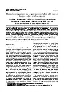
13]. Vibration causes a high-frequency noise which leads to defects on the surface of holes, accelerates wear, and decreases tool life [31]. It is possible to have an idea about tool wear by observing the levels of vibration signals. Sensors for measuring vibration signals are easily mounted on the workpiece/ machine tool. If the sensors are mounted very close to the cutting edge, the variation in the measured vibrations is too great during the drilling operation [31–33]. In this study, in order to collect vibration data, a Kistler 8762A50 three-axis accelerometer (acceleration range ±50 g, acceleration limit ±80 gpk, threshold nom. 0.0012 g, sensitivity 100 mV/g, mounted resonant frequency 30 kHz, frequency response 0.5–6000 Hz, amplitude nonlinearity ±1 % FSO, time constant nom. 1 s, transverse sensitivity max. 5 %) was placed approximately 40 mm away from the spindle of the CNC machine. A 4-mm-diameter hole was drilled on the workpiece material for the mounting of the acceleration sensor, the hole was tapped, and the sensor fixed with a screw in accordance with the tool center axes. The DasyLab 7.0 package program was used to collect the vibration data created during the tests into the computer environment. Lastly, the acceleration amplitude data was resolved by the aid of JMP 8.0 and MINITAB 16.0 statistical software. The procedural setup for the experimental study, vibration measurement, and evaluation of measurement results is given in Fig. 1. Tool wear values were measured for each drilling condition. At the end of the drilling operations, the drill bits were observed under a JEOL JSM6060 LW scanning electron microscope (SEM) and an optical microscope in order to study the mechanism of the tool wear.
3 Experimental results and discussion Acceleration amplitude values vary depending on the workpiece hardness, drill length, cutting speed, feed rate, and number of holes. In Table 6, the acceleration amplitude data measured at different levels of process parameters are given. In the measurement results obtained in the tests realized at different Chemical composition of the drills
Table 4 Si
V
Cr
Mn
Ni
Nb
Mo
Co
Fe
3.709
1.95
3.97
0.046
0.688
0.792
6.469
4.382
77.993
Int J Adv Manuf Technol Table 5 Process parameters used in the experiments and their levels
Process parameters
Symbol
Unit
Levels
Workpiece hardness (AISI steel) Drill length (tool overhang) Cutting speed Feed rate Number of holes
H Ld V f Nh
HRC mm m/min mm/rev –
20 (AISI D2 steel), 28 (AISI D3 steel) 133 (93): drill 1, 184 (144): drill 2 5, 10, 15 0.04, 0.05, 0.06 1, 2, 3,....,20
levels of process parameters and in the FF design test setup, as the number of holes increased, the acceleration amplitude also increased (Table 6, Fig. 2). Since the number of tests performed for the evaluation was very high, the acceleration amplitude measurement results of the 1st and 20th holes, or of the last holes drilled by the drills that completed their tool life before reaching the 20th hole, were used (Table 6). In the statistical resolutions, 615 measurement results were evaluated. In the hole drilling operations at different levels of process parameters, the lowest acceleration amplitude values (A1: 0.164 mm/s2, 1st hole) were obtained in drilling at the cutting conditions of V 5 m/min, f 0.06 mm/rev with AISI D3 cold work tool steel HSS drills having a hardness of 28 HRC and length of 133 mm. The highest acceleration amplitude values (A2: 6.054 mm/s2, 20th hole) were obtained in drilling at the cutting conditions of V 15 m/min, f 0.04 mm/rev with AISI D2 cold work tool steel HSS drills with a hardness of 20 HRC and length of 184 mm. It can be understood from Table 6 that the selection of a lower cutting speed and higher feed rate would have been more appropriate, as would the use of shorter drills in order to obtain lower acceleration amplitude values in the drilling of the AISI D3 cold work steel with the higher hardness.
3.1 Main effects of process parameters on acceleration amplitude and tool wear and acceleration amplitude relations Main effect graphics show the types of effects of dependent variables (output parameters) at different levels of independent variables (input parameters) [28–30]. In the drilling of AISI D2 and AISI D3 steels with HSS twist drills having two different lengths, the main effects of the process parameters on acceleration amplitude (A) are shown in Fig. 2. The most important parameters affecting acceleration amplitude were the number of holes (Nh), workpiece hardness (H), cutting speed (V), and feed rate ( f ), while no significant effect was observed with drill length/tool overhang (Ld). 3.1.1 The effects of workpiece hardness In the drilling of AISI D2 and AISI D3 cold work tool steels at a constant V 5 m/min cutting speed and f 0.05 mm/rev feed rate, the effect of workpiece hardness on the variation of acceleration amplitude values, depending on the number of holes and hole depth, is given in Fig. 3. It can be seen that
Fig. 1 Schematic diagram of the experimental procedure
Jonford CNC Milling Machine
Terminal Board
Kistler 5108A Piezotron Coupler
Kistler 8762A50 Accelerometer
Workpiece
PCI-1710HG Chart
DasyLab 7.0 Package Program
JMP 8.0 and MINITAB 16.0 Stastistical Software
H
Ld
Experimental results
V
f
Nh 0.715 3.899 0.447 1.770 0.302 0.823 0.969 4.260 0.783 4.611 0.639 2.771 0.390 3.030 0.937 4.563 0.874 1.240 0.273 1.870 2.022 3.010 0.164A1 0.720 0.290 4.787 0.825 3.792 0.556 2.341 0.610 1.545 2.377 3.986 0.910 1.016
Acceler. (A)
267
2*
7*
6*
20
20
20
20
5*
20
3*
8*
20
20
20
20
16*
20
20
Drilled hole numbers
H
Ld
V
f
Nh
268 20 133 5 0.04 1 287 20 133 5 0.04 20 288 20 133 5 0.05 1 307 20 133 5 0.05 20 308 20 133 5 0.06 1 326 20 133 5 0.06 19 327 20 133 10 0.04 1 346 20 133 10 0.04 20 347 20 133 10 0.05 1 366 20 133 10 0.05 20 367 20 133 10 0.06 1 386 20 133 10 0.06 20 387 20 133 15 0.04 1 406 20 133 15 0.04 20 407 20 133 15 0.05 1 426 20 133 15 0.05 20 427 20 133 15 0.06 1 446 20 133 15 0.06 20 447 20 184 5 0.04 1 466 20 184 5 0.04 20 467 20 184 5 0.05 1 486 20 184 5 0.05 20 487 20 184 5 0.06 1 506 20 184 5 0.06 20 507 20 184 10 0.04 1 526 20 184 10 0.04 20 527 20 184 10 0.05 1 546 20 184 10 0.05 20 547 20 184 10 0.06 1 566 20 184 10 0.06 20 567 20 184 15 0.04 1 586 20 184 15 0.04 20 587 20 184 15 0.05 1 600 20 184 15 0.05 14 601 20 184 15 0.06 1 615 20 184 15 0.06 15 Total drilled hole number in drilling of AISI D2 steel Total drilled hole number
Trial no.
*The number of drilled holes in this cutting conditions. The drill lost its tool life before drilling 20 holes
1 28 133 5 0.04 1 20 28 133 5 0.04 20 21 28 133 5 0.05 1 40 28 133 5 0.05 20 41 28 133 5 0.06 1 56 28 133 5 0.06 16 57 28 133 10 0.04 1 76 28 133 10 0.04 20 77 28 133 10 0.05 1 96 28 133 10 0.05 20 97 28 133 10 0.06 1 116 28 133 10 0.06 20 117 28 133 15 0.04 1 136 28 133 15 0.04 20 137 28 133 15 0.05 1 144 28 133 15 0.05 8 145 28 133 15 0.06 1 147 28 133 15 0.06 3 148 28 184 5 0.04 1 167 28 184 5 0.04 20 168 28 184 5 0.05 1 172 28 184 5 0.05 5 173 28 184 5 0.06 1 192 28 184 5 0.06 20 193 28 184 10 0.04 1 212 28 184 10 0.04 20 213 28 184 10 0.05 1 232 28 184 10 0.05 20 233 28 184 10 0.06 1 252 28 184 10 0.06 20 253 28 184 15 0.04 1 258 28 184 15 0.04 6 259 28 184 15 0.05 1 265 28 184 15 0.05 7 266 28 184 15 0.06 1 267 28 184 15 0.06 2 Total drilled hole number in drilling of AISI D3 steel
Trial no.
Table 6
0.473 3.269 0.460 4.199 0.532 5.060 1.680 5.947 1.281 5.910 0.541 2.429 0.688 3.835 0.795 5.847 1.560 4.755 0.566 2.240 1.291 5.761 0.349 1.496 1.050 4.567 1.284 5.468 0.463 5.939 2.043 6.054A2 1.525 5.131 0.852 3.930
Acceler. (A)
348 615
15*
14*
20
20
20
20
20
20
20
20
20
20
20
20
20
19*
20
20
Drilled hole numbers
Int J Adv Manuf Technol
Int J Adv Manuf Technol
Fig. 2 Main effects of the process parameters on acceleration amplitude
in the drilling of AISI D3 steel (H 28 HRC), which possesses high hardness, lower acceleration amplitude values were obtained. In the drilling of both of the workpieces, as the number of holes and hole depth increased, acceleration amplitude values also increased (Fig. 3a, b). Figure 4 gives the tool wear patterns in the drilling of workpieces having different hardnesses. After the drilling of the AISI D2 workpiece, having a hardness of 20 HRC, flank wear was observed on the cutting edges of the drill (Fig. 4a). In the drilling of the AISI D3 steel workpiece, with a hardness of 28 HRC, formations of BUE, flank wear, outer corner wear, and chisel edge wear types were observed (Fig. 4b). In their study, Orhan et al. investigated the changes in the vibration and the tool wear during the end milling of AISI D3 cold work tool steel having a hardness of 35 HRC. They found that vibration amplitude was increased with the progression of tool wear [34]. It is very well known that in cutting operations, BUE formation accelerates tool wear, spoils the finished surface of the workpiece, and causes vibrations in the cutting tool/workpiece/machining center [13]. The flank wear occurred on the cutting edge of the cutting tool and the lower rigidity due to lower workpiece
a) AISI D2 cold work tool steel, H:20 HRC, V: 5 m/min, f: 0.05 mm/rev
Fig. 3 Effects of workpiece hardness on acceleration amplitude
hardness was the reason for the greater acceleration amplitude in the drilling of the workpiece of lower hardness, although no BUE formation was observed. Moreover, when the experimental results given in Table 6 were investigated, it can be seen that, under the same cutting conditions, only 267 holes could be drilled in the AISI D3 steel (trials 1–267) having 28 HRC, while 348 holes were drilled in the AISI D2 steel having 20 HRC. Because of the lower hardness value of the workpiece, higher tool life was achieved during the drilling of the AISI D2 steel under the same cutting conditions due to less tool wear. For this reason, it was possible to measure the acceleration amplitude reliably and efficiently during the drilling of 20 holes. Due to the sudden and extreme tool wear which occurred in the drilling process of the higher hardness AISI D3 steel, the drill bits losted their life before completing the drilling of 20 holes. As shown in Table 6, only two or three holes could be drilled under some cutting conditions (e.g., trial nos. 145–147 and trial nos. 266–267). In this study, acceleration amplitude measurements for each experiment were carried out for the drill bits that could efficiently drill 20 holes. The extreme deviations in acceleration amplitude values were
b) AISI D3 cold work tool steel, H: 28 HRC, V: 5 m/min, f: 0.05 mm/rev
Int J Adv Manuf Technol Fig. 4 SEM images of tool wear patterns in the drilling of AISI D2 steel and AISI D3 steel (V 15 m/ min, f 0.06 mm/rev)
Flank wear
BUE Flank wear Outer corner wear BUE Chisel edge wear
a) H:20 HRC, Nh: 20 holes
excluded when acceleration amplitude measurements were halted because tool life had ended before 20 holes due to tool wear. In the process of drilling the AISI D3 steel, the drill bits losted their life; thus, they had drilled fewer holes and higher acceleration amplitude values were obtained because acceleration amplitude values increase with the increasing number of holes. 3.1.2 The effects of drill length/tool overhang The least effective parameter on acceleration amplitude was drill length/tool overhang (Ld), while with the increasing of drill length/tool overhang, acceleration amplitude increased slightly (Fig. 2). The reason for this was the extreme wear caused by excessive chatter [35] and the reduced damping of the 184-mm-long drill 2 (one of the drills having different overhangs) compared to the 133-mm-long drill 1 (having an overhang of 93 mm). This was due to possible deflection and oscitation at very low values against the thrust force during drilling (Fig. 5a, b). If, in the turning process, the tool overhang selected is higher than necessary, acceleration amplitude increases due to radial forces created in the cutting tool. Thus, in the study made by Khalili and Danesh, in the turning of a brass workpiece by a coated carbide tool, tool vibrations increased with increasing tool overhang [5]. Kayhan and Budak collected tool wear data in turning and milling of different Fig. 5 Optical microscopy photograph of tool wear patterns in the drilling of workpieces with HSS twist drills of different lengths. Workpiece AISI D3 cold work steel, f 0.06 mm/rev
b) H: 28 HRC, Nh:14 holes
work materials under stable and chatter conditions and analyzed the effects of cutting conditions as well as severity of chatter on tool life. The results showed that the severity of chatter and thus the vibration amplitude greatly reduced the life of cutting tools. Tool life was significantly affected by the holder length, i.e., the dynamic rigidity or vibration amplitude [35]. In drilling hole operations, cutting drill length/overhang does not have a significant effect on the acceleration amplitude, since the thrust force is in the foreground [33]. In drillings made under the same conditions, flank wear, outer corner wear, margin wear, and chisel edge wear occurred on the 184-mm-long drill (drill 2) (Fig. 5b). These types of wear affected the drilling performance of the drills. The cutting edge of the drill could barely remove the chips and, consequently, thrust force and vibration increased. Although the hardnesses of the workpieces were lower, the drilling capabilities of the drills were reduced due to wear, chip formation, difficulty of chip disposal, and the difficulties in drilling the workpieces. Therefore, the development of vibrations was inevitable. 3.1.3 The effects of cutting speed Cutting speed (V) is another important parameter on vibration which shortens tool life. The increasing tool wear at higher cutting speeds causes the cutting forces, chatter, and vibration
Chisel edge wear
Flank wear
Chisel edge wear
Margin wear
Flank wear
a) Ld: 133 mm, Nh: 20 holes
Outer corner wear b) Ld: 184 mm, Nh: 20 holes
Int J Adv Manuf Technol
to increase [32, 35]. Cutting tool lives are typically shortened by 50 to 80 % at higher cutting speeds due to chatter vibrations [35]. In Fig. 6a–c, the variations of acceleration amplitude values are given for the drilling of AISI D3 cold work tool steel at a constant feed rate of f 0.05 mm/rev at three different cutting speeds. At the lower cutting speeds, depending on the increase in the number of holes and hole depth, a gradual increase occurred in the acceleration amplitude values (Fig. 6a), while at higher cutting speeds, acceleration amplitude values increased rapidly (Fig. 6b, c). In the drilling of AISI D2 and AISI D3 steels, by raising the cutting speed from V 5 m/min to V 15 m/min, the amplitude value was increased by approximately 175 % (Fig. 2). Moreover, in the end milling operation of stainless steel, the acceleration amplitude increased with the increase of cutting speed and feed rate [32]. Again, in the turning of Al6063, acceleration amplitude increased with the increasing cutting speed and feed rate [3]. In the milling of AISI 1050 steel, Dilipak and Yılmaz [10] attributed the increase of acceleration amplitude depending on the cutting speed increase to the greater friction between the cutting tool and the workpiece created per unit time with the increasing cutting speeds and to the decrease of idle time. The greater friction created per unit time increases tool wear and shortens tool life. In the drilling of the AISI D3 steel at the f 0.06 mm/rev and V 15 m/ min cutting conditions, flank wear, chisel edge wear, outer corner wear, and BUE were observed in the
cutting tool (Fig. 7a–c). The excessive wear occurred in the cutting tool at higher cutting speeds and the steady BUE formation were the main reasons for the increase in the acceleration value. In the machining of steel materials, the cutting speed affects the formation of BUE in three different regions. The first region is the BUE initiation region, formed on the tool rake face at very low cutting speeds of 0.8–4 m/min. In this region, due to chip fracture, cutting force oscillations, and significant variation of vibration amplitude in an irregular pattern occurs with increasing cutting speed. The steady BUE region occurs at the lower cutting speeds of 4– 20 m/min. In this region, BUE is always unstable, and the structure of the material irregular. In the steady BUE region, vibration amplitude steadily increases with increasing cutting speeds. In cutting tests, continuous chips with a tight chip curl are observed. The unsteady BUE region occurs at relatively high cutting speeds like 20–100 m/min. Due to the increase in cutting speed, the chips flowing over the tool rake face periodically fracture the BUE, and thus, the process of BUE formation is occasionally broken. The vibration amplitude keeps nearly constant with increasing cutting speeds. In cutting tests, continuous chips with less curl are observed [13]. Therefore, the unstable BUE (unsteady BUE region) and acceleration amplitude observed in the drilling of the AISI D3 steel steadily increased at the cutting conditions of f 0.06 mm/rev and V 15 m/min
a) V: 5 m/min
b) V: 10 m/min
c) V: 15 m/min Fig. 6 The effects of cutting speed on acceleration amplitude. Workpiece AISI D3 cold work steel, f 0.05 mm/rev
Int J Adv Manuf Technol Fig. 7 SEM images of tool wear patterns in the drilling of AISI D3 steel at different cutting speeds (f 0.06 mm/rev)
Chisel edge wear Chisel edge wear
BUE Flank wear Outer corner wear BUE Chisel edge wear
a) V: 5 m/min, Nh: 17 holes 3.1.4 The effects of feed rate While the acceleration amplitude increased with the raising of the feed rate from f 0.04 mm/rev to f 0.05 mm/rev, the lowest acceleration amplitude value was reached at the highest feed rate (Fig. 2). The reason for reaching the highest acceleration value at f 0.05 mm/rev feed rate was that the tool life ended after drilling 10 holes, due to increase in the flank wear and outer corner wear of the cutting tool (Fig. 8b). With the increase in the feed rate from f 0.04 m/rev to f 0.06 mm/rev, flank wear, outer corner wear, chisel edge wear, and BUE increased as well (Fig. 8a–c). However, the cutting tool life did not finish until the fifteenth hole [33]. In the milling of AISI 1050 steel, acceleration amplitude also increased with the increasing feed rate. This was explained by the increase in the power requirement of the CNC machining center, with the increased feed rate consequently affecting the cutting frequencies adversely [10]. In the turning of 2024-T351 aluminum alloy at the three different cutting speeds of 1, 50, and 100 m/min and in the feed rate interval of 0.01–0.20 mm/rev, vibration amplitude increased with the increasing feed rate. Further increase in the feed rate caused the BUE to disappear completely into the base of a discontinuous chip. Vibration amplitude was influenced by the cutting speed, the feed rate, and their interaction. The cutting speed contributed to 53 % of the total variation of cutting vibrations, followed by the feed rate, which results in 33.3 % of the total variation. However, in the same study, in turning at 50 m/min cutting speed and approximately 0.08–0.10 mm/rev, vibration amplitude decreased, depending on the increase of the feed rate [13]. The present study on the drilling of AISI D2 and AISI D3 cold work tool steels using HSS twist
Fig. 8 Tool wear patterns in the drilling of AISI D3 steel at different feed rates (V 15 m/min)
b) V: 10 m/min, Nh: 20 holes
c) V: 15 m/min, Nh: 14 holes
drills demonstrated an increase of acceleration amplitude at f 0.04–0.05 mm/rev and then a decrease at f 0.05– 0.06 mm/rev (Fig. 2), thus showing results similar to those of the study carried out by Fang et al., where cutting speed was also found to be more effective than feed rate [13]. 3.1.5 The effects of the number of holes The most effective parameter on acceleration amplitude is the number of holes drilled (Fig. 2). In the tests made under all the cutting conditions, as the number of holes drilled increased, acceleration amplitude increased constantly (Figs. 3, 6, and 9). The reason for this was the increasing of tool wear, depending on the number of holes drilled, and the increase in chatter formation due to the degree of difficulty of the cutting operation. Tool wear is directly related to drilling time and consequently to the number of holes drilled. When drill bit wear begins to occur, difficulties arise in the machining process due to factors such as increasing cutting force, internal fracture, and local weldings between cutting tool and workpiece. These cause the vibration of the machine tool. Vibration causes a high-frequency noise, leads to defects in the hole surface, and accelerates tool wear, thereby reducing cutting tool life. Excessive increases in vibration result in chatter vibration, one of the most significant factors in reducing the performance of the tool. Chatter vibration leads to extreme wear of the cutting edges of the tool, which has an undesirable effect on the tool life. Uncontrollable vibrations cause defects in the shape and surface quality of the workpiece, make it impossible to obtain sensitive measurements, increase cutting tool wear, cause fracture
BUE Chisel edge wear
Outer corner wear Flank wear Flank wear
Flank wear BUE
a)
f: 0.04 mm/rev, Nh: 20 holes
b)
f: 0.05 mm/rev, Nh: 10 holes
c)
f: 0.06 mm/rev, Nh:14 holes
Int J Adv Manuf Technol
study. It is thought that during the experimental study, the uncontrollable factors increased the residuals. A ¼ −0:30 þ 0:135H−0:005Ld−0:507V þ 69:3 f þ 0:35N h−0:000366HLd þ 0:00293HV −2:09H f −0:00822HN h þ 0:0029LdV −0:211Ld f −0:000083LdNh þ 0:924V f þ 0:0056V N h−1:28f N h Fig. 9 Effects of the number of holes on acceleration amplitude. Workpiece AISI D2 cold work steel, V 10 m/min, f 0.05 mm/rev
of the machine elements, and more importantly, cause machine tool damage. 3.2 Predictive equation and analysis of variance for acceleration amplitude For the estimation of the acceleration amplitude occurred in the drilling of AISI D2 and AISI D3 cold work tool steels using HSS twist drills, a second-order equation involving the main and interaction effects of the process parameters was developed by regression analysis (Eq. 1). As seen from this equation, while Ld, V, H*Ld, H*f, H*Nh, Ld*f, Ld*Nh, and f*Nh have negative effects on acceleration amplitude, H, f, Nh, H*V, and Ld*V have additive effects. The predicted R2 (70.3 %) value and the adjusted R2 value (69.5 %) matched with the experimental results. The adjusted R2 determines the amount of deviation about the mean which is described by the model. The predicted R2 value and the adjusted R2 value were found to be in good agreement. In Fig. 10, the normal probability plot is given. From this figure, it is seen that points are placed on a straight line or distributed close to a straight line; therefore, it can be concluded that the data exhibit a normal distribution. The reason that not all the data were on a straight line can be attributed to the significant number of tests in this
Fig. 10 Normal probability plot for acceleration amplitude
ð1Þ
Analysis of variance (ANOVA) is a statistically based, objective decision-making instrument used for determining any difference in the average performance of the groups of items tested [36]. In this study, the purpose of using ANOVAwas the investigation of the process parameters (control factors and their interactions) affecting acceleration amplitude significantly (Table 7). In Table 7, the percentage contribution is the ratio of the sum of the square of each factor to the total sum of the square. For the purpose of determining a significant effect of each process parameter on the performance characteristic, the F test was carried out. The F value is the ratio of the mean of the squares to the mean of the squared error. The process parameters with larger F values have a greater effect on the acceleration amplitude. An F value of a process parameter greater than the tabulated F ratio shows that the process parameter has a significant effect on the acceleration amplitude. When the F value of a process parameter is high, its percentage contribution is high as well. The ANOVA results expressing the effects of each process parameter on the acceleration amplitude, depending on the F value and percentage contribution, are given in Table 7. The most important parameter on acceleration amplitude was the number of holes (Nh), with a 39.78 % contribution (F value>tabulated F ratio at 95 % confidence level: F0.05;1;4 =1.61). When the F tabulated values are considered, the other important parameters were workpiece hardness (11.72 %), cutting speed (10.28 %), drill length*cutting speed (5.32 %), feed rate (4.17 %), workpiece hardness*number of holes (2.56 %), drill length*feed rate (1.79 %), and cutting speed*feed rate (1.27 %). Other process parameters had no significant effect on the acceleration amplitude. Abuthakeer et al. [3] specified that in the turning of Al6063, the cutting speed (35 %) was more effective than the feed rate (27 %) on the amplitude of acceleration level of vibration. In the turning of 2024-T351 aluminum alloy, the cutting speed and feed rate were effective 53 and 33.3 %, respectively [13]. The results of the present study are similar to the results of the studies conducted by Abuthakeer et al. [3] and Fang et al. [13], as the cutting speed (10.28 %) was more effective on the acceleration amplitude than the feed rate (4.17 %) in the drilling of AISI D2 and AISI D3 cold work steels. In contrast to the present findings, in the milling of AISI
Int J Adv Manuf Technol Table 7 ANOVA results for acceleration amplitude
Source
Df
Workpiece hardness, H Drill length, Ld Cutting speed, V Feed rate, f Number of holes, Nh Workpiece hardness*drill length, H*Ld Workpiece hardness*cutting speed, H*V Workpiece hardness*feed rate, H*f Workpiece hardness*number of holes, H*Nh Drill length*cutting speed, Ld*V Drill length*feed rate, Ld*f Drill length*number of holes, Ld*Nh Cutting speed*feed rate, V*f Cutting speed*number of holes, V*Nh Feed rate*number of holes, f*Nh Error Total
1050 steel, the feed rate (28.8 %) was found to be more effective than the cutting speed (10.1 %) [10]. In the turning of AISI 1045 steel, the main cutting parameters of cutting speed, feed rate, and chip depth had no significant effect, while the most effective parameter was shown to be tool overhang (93.07 %) [12]. Contrary to the work conducted by Aleksandrovich and Siamak, the main effect of the drill length (tool overhang) was calculated as less than 1 % in the present study.
4 The interaction effects of process parameters on acceleration amplitude The interaction effect graphs show the effect of the interactions of each independent variable on the dependent variable [30]. According to the ANOVA results (Table 7), the process parameter interactions having a significant effect (F ratio>F table) on acceleration are given in Fig. 11. In Fig. 11a, the variation of acceleration amplitude depending on the drill length*cutting speed (Ld*V) interaction is given, and it can be seen that in the drilling of AISI D2 and AISI D3 steel cold work tool steels by short HSS twist drills, lower acceleration amplitude values can be obtained at a lower cutting speed. The effect of workpiece hardness on acceleration amplitude was not seen explicitly in the first holes, whereas workpiece hardness became evident as the number of holes increased. In the drilling of AISI D2 and AISI D3 workpieces having different hardnesses, as the number of holes increased, acceleration amplitude increased.
Sum of squares
Mean square
F ratio
F table
% Contribution
1 1 2 2 19 3 5 5 37
107.12 0.00 93.90 38.07 363.45 2.53 0.04 2.60 23.37
107.12 0.00 46.95 19.04 19.13 0.84 0.01 0.52 0.63
244.27* 0.01 107.06* 43.41* 43.62* 1.92 0.02 1.18 1.45*
3.87 3.87 3.02 3.02 1.61 2.63 2.24 2.24 1.44
11.72 0.00 10.28 4.17 39.78 0.28 0.00 0.28 2.56
5 5 39 7 40 50 393 614
48.57 16.38 1.33 11.59 20.87 11.58 172.34 913.74
9.71 3.28 0.03 1.66 0.52 0.23 0.44
22.15* 7.47* 0.08 3.77* 1.19 0.53
2.34 2.34 1.43 2.03 1.43 1.38
5.32 1.79 0.00 1.27 2.28 1.27 18.86 100.00
This increase was higher in the drilling of the workpieces of lower hardness (Fig. 11b) because the workpieces with higher hardness provided greater rigidity. The variation of acceleration amplitude depending on the feed rate-drill length interaction is given in Fig. 11c. In drilling with the shorter drills, no significant effect of feed rate on acceleration amplitude was observed, while the feed rate created a significant effect in the case of the longer drills. A higher acceleration amplitude was obtained at lower feed rates with the shorter drills, whereas the highest acceleration amplitude was obtained at medium feed rate values with the longer drills (Fig. 11c). The lowest acceleration amplitude was obtained at the highest feed rate values with the longer drills. This result can be attributed to the prevention of chatter formation due to easy chip removal in the cutting zone with the increasing feed rate. Lastly, the variation of acceleration amplitude depending on the feed rate and cutting speed interaction is given in Fig. 11d. The effect of cutting speed on acceleration amplitude was more than that of feed rate. The lowest acceleration amplitude values were obtained at the lowest cutting speed and highest feed rate.
5 Conclusions This study investigated the effects of workpiece hardness, tool length/tool overhang, cutting speed, feed rate, and the number of holes drilled on the acceleration amplitude in the drilling of
Int J Adv Manuf Technol
a) Ld*V, Contribution 5.32 %
b) H*Nh, Contribution 2.56 %
c) Ld*f, Contribution 1.79 %
d) V*f, Contribution 1.27 %
Fig. 11 Interaction effects of the process parameters on acceleration amplitude
AISI D2 and AISI D3 cold work tool steels using HSS twist drills of two different lengths. The following results were obtained: &
&
&
A second-order equation involving the main effects and interaction effects of the process parameters on acceleration amplitude was developed at a 95 % confidence level, and the correlation coefficient of this equation was calculated as R2 =0.703. The most important parameters affecting acceleration amplitude were number of holes (39.78 %), workpiece hardness (11.72 %), cutting speed (10.28 %), drill length*cutting speed (5.32 %), feed rate (4.17 %), workpiece hardness*number of holes (2.56 %), drill length*feed rate, (1.79 %), and cutting speed*feed rate (1.27 %). Other process parameters had no significant effects on acceleration amplitude. Acceleration amplitude increased with the increasing cutting speed, number of holes drilled, and drill length, but it decreased with the increasing workpiece hardness. With an increase of feed rate, there was at first an increase in the acceleration amplitude from 0.04 to 0.05 mm/rev and then a decrease from 0.05 to 0.06 mm/rev.
&
The lowest acceleration amplitude values were obtained in the drilling of AISI D3 cold work tool steel having a hardness of 28 HRC by using the 133-mm-long HSS twist drills at the low cutting speed of V 5 m/min and high feed rate of f 0.06 mm/rev. As the number of holes drilled increased, acceleration amplitude increased as well. The tool wear types on the worn drills determined by the optical microscopy and SEM observations were related to acceleration amplitude. Flank wear, chisel edge wear, outer corner wear, margin wear, and BUE were observed on the worn drills. It was concluded that drill wear increased the acceleration amplitude values.
&
References 1.
2. 3.
Kaplan Y, Okay Ş, Motorcu AR, Nalbant M (2014) Investigation of the effects of machining parameters on the thrust force and cutting torque in the drilling of AISI D2 and AISI D3 cold work tool steels. Indian J Eng Mater S 21:128–138 Şahin Y (2003) İmal Usulleri. Gazi Kitabevi, Ankara Abuthakeer SS, Mohanram PV, Mohan Kumar G (2011) Prediction and control of cutting tool vibration in CNC lathe with Anova and ANN. I. J Lean Think 2:1–23
Int J Adv Manuf Technol 4.
5.
6. 7.
8.
9.
10.
11.
12.
13.
14. 15.
16.
17.
18.
19.
20.
Izelu CO, Eze SC, Oreko BU, Edward BA, Garba DK (2013) Response surface methodology in the study of induced machining vibration and work surface roughness in the turning of 41Cr4 alloy steel. Int J Emerg Technol Adv Eng 3:13–17 Khalili K, Danesh M (2013) Investigation of overhang effect on cutting tool vibration for tool condition monitoring. J Meas Eng 1:171–177 Stephenson AD, Agapiou JS (2006) Metal cutting theory and practice. Taylor and Francis Group, New York Kaplan Y (2010) Effects of different parameters on cutting force, torque, vibration, surface roughness, tool wear and exit burrs in drilling. Dissertation, Gazi University Abuthakeer SS, Mohanram PV, Mohankumar G (2011) The effect of spindle vibration on surface roughness of workspiece in dry turning using ANN. I. J Lean Think 2:42–58 Ay M, Turhan A (2011) Determination and optimization of the effect of cutting parameters and workpiece length on the geometric tolerances and surface roughness in turning operation. Int J Phys Sci 6:1074–1084. doi:10.5897/IJPS11.130 Dilipak H, Yılmaz V (2012) Investigation of vibrations and statistical analysis in milling of AISI 1050 steel with carbide tools. J Fac Eng Archit Gazi Univ 27:285–294 Vinay BG, Janakinandan N, Suresh BG (2013) The impact of cutting conditions on cutting forces and chatter length for steel and aluminum. Int J Eng Adv Technol 2:919–924 Aleksandrovich RV, Siamak G (2014) The effect of tool construction and cutting parameters on surface roughness and vibration in turning of AISI 1045 steel using Taguchi method. Mod Mech Eng 4:8–18. doi:10.4236/mme.2014.41002 Fang N, Pai PS, Mosquea S (2010) The effect of built-up edge on the cutting vibrations in machining 2024-T351 aluminum alloy. Int J Adv Manuf Technol 49:63–71. doi:10.1007/s00170-009-2394-z Sanjay C (2007) Drill wear monitoring by vibration signature analysis. J Inst Eng Malaysia 68:22–26 Rahim EA, Kamdani K, Sharif S (2008) Performance evaluation of uncoated carbide tool in high speed drilling of Ti6Al4V. J Adv Mech Des Syst 2:522–531. doi:10.1299/jamdsm.2.522 Kurt M, Kaynak Y, Bagci E (2008) Evaluation of drilled hole quality in Al 2024 alloy. Int J Adv Manuf Technol 37:1051–1060. doi: 10.1007/s00170-007-1049-1 Panda SS, Chakraborty D, Pal SK (2008) Flank wear prediction in drilling using back propagation neural network and radial basis function network. Appl Soft Comput 8:858–871. doi:10.1016/j. asoc.2007.07.003 Ramkumar J, Malhotra SK, Krishnamurthy R (2004) Effect of workpiece vibration on drilling of GFRP laminates. J Mater Process Technol 152:329–332. doi:10.1016/S0924-0136(03) 00622-8 Zhang JZ, Chen JC (2009) Surface roughness optimization in a drilling operation using the Taguchi design method. Mater Manuf Process 24:459–467. doi:10.1080/10426910802714399 Ahmadi K, Altintas Y (2013) Stability of lateral, torsional and axial vibrations in drilling. Int J Mach Tool Manuf 68:63–74. doi:10. 1016/j.ijmachtools.2013.01.006
21.
Messaoud A, Weihs C, Hering F (2008) Detection of chatter vibration in a drilling process using multivariate control charts. Comput Stat Data Anal 52:3208–3219. doi:10.1016/j.csda.2007.09.029 22. Imani BM, Moosavi SG (2009) Time domain simulation of torsional-axial and lateral vibration in drilling operation. Proceeding of International Conference on Applications and Design in Mechanical Engineering (ICADME) 11-13 October, Batu Ferringhi Penang, Malaysia, 1-7 23. Bayly PV, Metzler SA, Schaut AJ, Young KA (2000) Theory of torsional chatter in twist drills: model, stability analysis and composition to test. J Manuf Sci Eng 123:552–561. doi:10.1115/1. 1381399 24. Mehrabadi IM, Nouri M, Madoliat R (2009) Investigating chatter vibration in deep drilling, including process damping and the gyroscopic effect. Int J Mach Tool Manuf 49:939–946. doi:10.1016/j. ijmachtools.2009.06.009 25. Stone E, Askari A (2002) Nonlinear models of chatter in drilling processes. Dyn Syst 17:65–85. doi:10.1080/14689360110105788 26. Huang BW (2003) Dynamic characteristics of a drill in the drilling process. P I Mech Eng B-J Eng 217:161–167. doi:10.1243/ 095440503321148803 27. Kaplan Y, Nalbant M, Gökkaya H (2011) The experimental investigation of the effect of machining parameters on burr formation in drilling of AISI D2 and AISI D3 cold work steels. Karaelmas Sci Eng J 1:37–46. doi:10.7212%2Fzkufbd.v1i1.11 28. Akman G, Özkan C (2011) Solving adhesion problem in metal sheet manufacturing with design of experiments. Dogus Univ J 12:187–199 29. Breyfoglef W (2003) Implementing six sigma: smarter solutions using statistical methods. John Wiley & Sons, New York 30. Lazic´ ZR (2004) Design of experiments in chemical engineering: a practical guide. Wiley-VCH, Weinheim 31. Amin AKMN, Imran M, Arif M (2002) Influence of cutting parameters on chatter and tool wear during end milling of stainless steel conducted on VMC. IIUM Eng J 3:1–15 32. Ertunç HM, Sevim İ (2001) Studies on tool wear condition monitoring. Pamukkale Univ J Eng Sci 7:55–62 33. Okay S, Kaplan Y, Motorcu AR, Nalbant M (2013) Evaluation of cutting tool wear characteristics and removed chip volumes in drilling of AISI D2 and AISI D3 cold work tool steels. 7th International Advanced Technologies Symposium (IATS’13) 30 October-1 November, Istanbul, Turkey 34. Orhan S, Er AO, Camuşcu N, Aslan A (2007) Tool wear evaluation by vibration analysis during end milling of AISI D3 cold work tool steel with 35 HRC hardness. NDT&E Int 40:121–126. doi:10.1016/ j.ndteint.2006.09.006 35. Kayhan M, Budak E (2009) An experimental investigation of chatter effects on tool life. P I Mech Eng B-J Eng 223:1455–1463. doi: 10.1243/09544054JEM1506 36. Durairaj M, Sudharsun D, Swamynathan N (2013) Analysis of process parameters in wire EDM with stainless steel using single objective Taguchi method and multi objective grey relational grade. Proc Eng 64:868–877. doi:10.1016/j.proeng.2013.09.163