C. I. Kim P. Schiavone1 e-mail:
[email protected]
C.-Q. Ru Department of Mechanical Engineering, University of Alberta, Edmonton, AB, T6G 2G8, Canada
The Effects of Surface Elasticity on an Elastic Solid With Mode-III Crack: Complete Solution We examined the effects of surface elasticity in a classical mode-III crack problem arising in the antiplane shear deformations of a linearly elastic solid. The surface mechanics are incorporated using the continuum based surface/interface model of Gurtin and Murdoch. Complex variable methods are used to obtain an exact solution valid everywhere in the domain of interest (including at the crack tip) by reducing the problem to a Cauchy singular integro-differential equation of the first order. Finally, we adapt classical collocation methods to obtain numerical solutions, which demonstrate several interesting phenomena in the case when the solid incorporates a traction-free crack face and is subjected to uniform remote loading. In particular, we note that, in contrast to the classical result from linear elastic fracture mechanics, the stresses at the (sharp) crack tip remain finite. 关DOI: 10.1115/1.3177000兴 Keywords: surface elasticity, mode-III crack, antiplane deformations, complete exact solution, Cauchy singular integro-differential equation
1
Introduction
Currently, the two fundamental approaches used in the modeling of the deformation of solids at the nanoscale involve either atomistic models or refined continuum models. The former rely on massive atomistic simulations, which most often require huge computational resources. Nonetheless, these models were used successfully to investigate problems of great interest in nanomechanics including several problems involving fracture and related issues 共see, for example, Refs. 关1–4兴兲. Refined continuum models offer the advantages of the continuum setting and the associated mathematical framework. This “refinement” of classical continuum theories to account for the nanoscale is most often achieved by incorporating the effects of surface mechanics on the structural boundaries of the solid in an attempt to account for the increasing surface area to volume ratio of structures at this scale. Experiments on various elastic structures 共e.g., beams, plates, and shells兲 showed that predictions from these continuum models had good agreement with corresponding results obtained from the atomistic simulations 共see, for example, Refs. 关5,6兴兲. One of the most important and accessible refined continuum models incorporates the effects of surface mechanics using the surface elasticity model of Gurtin and co-workers 关7,8兴. In this model, a surface is regarded as a thin elastic membrane perfectly bonded to the bulk solid. The additional surface stress contributed by the surface mechanics leads to highly unusual and nonstandard boundary conditions on the surface of the bulk solid. Consequently, the corresponding boundary value problems are not accommodated by existing classical theories and pose challenges not encountered previously in similar mathematical analyses. Nonetheless, the Gurtin and Murdoch assumptions were used successfully in a number of studies, for example, in nanocomposite mechanics 共see, for example, Refs. 关5,9–12兴兲. The analysis of stresses in an elastic solid incorporating one or more cracks is of fundamental importance in the understanding of failure and in the general deformation analysis of engineering ma1 Corresponding author. Contributed by the Applied Mechanics Division of ASME for publication in the JOURNAL OF APPLIED MECHANICS. Manuscript received January 9, 2009; final manuscript received May 31, 2009; published online December 11, 2009. Review conducted by Zhigang Suo.
Journal of Applied Mechanics
terials. In macroscopic models, the stresses at the crack tip are found to be infinite reflecting the fact that the crack front is usually taken to be perfectly sharp. In fact, an infinitely sharp crack in a continuum is a mathematical abstraction since, in reality, most crack tips are, in fact, blunt with a radius of convergence of the order compatible with the nanoscale. This suggests that a more accurate analysis of the region in the vicinity of a crack tip can be achieved at the nanoscale. In the context of a continuum model this means the incorporation of surface effects into the model of deformation. In fact, it was shown using atomistic models that the influence of surface energy is significant in the vicinity of the crack tip 关13兴. To this end, the authors in Ref. 关14兴 examined the contribution of surface effects on the near-tip stresses of a modeIII crack using the Gurtin–Murdoch theory under several simplifying assumptions including the assumption that the crack tip is blunt with a radius of convergence of the order compatible with the nanoscale. Approximate numerical results are presented using asymptotic and finite element methods. These results, however, are restricted to the vicinity of the crack tip and do not present a complete solution of the problem at hand. The authors also note the contributions made in Refs. 关15–18兴 in which the effects of surface stresses were considered in a range of different problems involving elastic solids. In each case, however, the results in Refs. 关15–18兴 employed simplified assumptions on the stress-strain relations used to model the effects of surface elasticity. In particular, the surface stress is taken to be independent of surface strain. This assumption, although leading to simplified and thus tractable mathematical models of the corresponding solid, sacrifice the rigor and accuracy of a more comprehensive theory. In this paper we present an exact complete 共valid throughout the domain of interest and not simply in the vicinity of the crack tip兲 solution of a traction-free mode-III crack problem in the antiplane shear deformations of a linearly elastic solid maintaining the assumption of a sharp crack tip. Surface effects are incorporated using the Gurtin–Murdoch surface elasticity model 共with complete constitutive relations on the surface of the solid兲 with the crack occupying a finite region of the real axis. Using complex variable techniques, we show that the nonstandard boundary conditions arising from the incorporation of the effects of surface elasticity on the crack face were reduced to the solution of a Cauchy singular integro-differential equation 关19兴. The latter is solved numerically using an adapted collocation technique 关20兴
Copyright © 2010 by ASME
MARCH 2010, Vol. 77 / 021011-1
Downloaded 11 Dec 2009 to 129.128.138.100. Redistribution subject to ASME license or copyright; see http://www.asme.org/terms/Terms_Use.cfm
leading to a complete solution throughout the elastic solid. In particular, it is shown that, in contrast to classical fracture mechanics 共where surface effects are neglected兲, the incorporation of surface elasticity eliminates the stress singularity at the 共infinitely sharp兲 crack tip and leads to the more accurate situation of a finite stress at the crack tip. In addition, we demonstrate that the corresponding stress distributions derived from our analysis show clear signs of size dependency and do indeed tend to classical solutions 关21,22兴 when the surface effects approach zero. Throughout the paper, we make use of a number of wellestablished symbols and conventions. Thus, unless otherwise stated, Greek and Latin subscripts take the values 1,3 and 1,2,3, respectively, summation over repeated subscripts is understood, 共x , y兲 and 共x , y , z兲 are generic points referred to orthogonal Cartesian coordinates in R2 and R3, respectively, and ␦ij is the Kronecker delta.
2 Antiplane Crack Problem With Surface Stress: Governing Equations It is well-known that in the absence of body forces, the equilibrium and constitutive equations describing the deformation of a linearly elastic, homogeneous, and isotropic 共bulk兲 solids are given by div B = 0
共1a兲
B = I3 Tr共兲 + 2
共1b兲
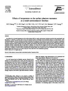
Fig. 1 Schematic of the problem
where and are the Lame constants of the material; B and are the stress and strain tensors, respectively; and I3 represents the identity tensor with respect to R3. 2.1 Surface Equation. We consider antiplane deformations of a linearly elastic and homogeneous isotropic solid occupying a cylindrical region in R3 with generators parallel to the z-axis of a rectangular Cartesian coordinate system. We assume that the cylinder is infinite in extent and is subjected to uniform remote shear stress. Suppose that the cylinder contains a single internal crack face 共with traction-free faces兲 running the length of the cylinder. In a typical cross section, the crack occupies the region 关−a , a兴, a 苸 R+ of the x-axis as shown in Fig. 1. The objective here is to incorporate the surface mechanics of the crack face into the model describing the antiplane deformations of the solid. In the Gurtin– Murdoch surface elasticity model, the authors regard a surface as a thin elastic membrane 共with elastic constants distinct from the bulk material兲 perfectly bonded to the surrounding material. Although Eqs. 共1a兲 and 共1b兲 remain true in the bulk material, equilibrium on the 共crack兲 surface is now described by the equations 共see Refs. 关7,8兴 for detailed derivations兲 关Bn兴 + divs s = 0
共2a兲
s = oI2 + 2共s − o兲εs + 共s + o兲Tr共εs兲I2
共2b兲
Here, the index s denotes the corresponding quantity resulting from the effects of surface elasticity, n represents the unit normal to the crack face, I2 is the identity tensor in R2, 关 ⴱ 兴 = 共 ⴱ 兲+ − 共 ⴱ 兲− denotes the jump of the corresponding quantity across the crack 共here “+” and “−” refer, respectively, to the upper face 共y ⬎ 0兲 and lower face 共y ⬍ 0兲 of the crack as depicted in Fig. 1兲, and o is the surface tension. We note that only surface strain components are included in Eq. 共2b兲 共i.e., strains normal to the surface are excluded兲. Finally, the surface divergence divs u is defined 共in general兲 by divs u = divs us − 2kun where k is the mean curvature and the displacement vector u admits the unique decomposition as follows: 021011-2 / Vol. 77, MARCH 2010
u = u s + u nn with us as the corresponding tangential displacement and un as the normal component of u. 2.2 Complex-Variable Formulation. Equation 共1b兲 is written in component form as
ij = ␦ijkk + ij
共3a兲
1
ij = 2 共ui,j + u j,i兲
共3b兲
In the antiplane shear of an isotropic elastic medium 共mode-III crack problem兲, we assume that the displacement vector u with components 共u , v , w兲 satisfies u = v = 0,
w = w共x,y兲,
2w 2w + =0 x2 y 2
共4兲
From Eq. 共3b兲, the strain components are now given by xz =
冉
冊
1 u w 1 w = + , 2 z x 2 x
yz =
冉
冊
1 w 1 w = + 2 z y 2 y
xy = xx = yy = zz = 0
共5兲
From Eq. 共5兲, the stress components can be written as
xz = 2xz =
w , x
yz = 2yz =
w y 共6兲
xy = xx = yy = zz = 0
Since w共x , y兲 is a harmonic function, we denote by 共x , y兲 its conjugate harmonic function. Introducing the complex variable z = x + iy, we can now write w = Re关⍀共z兲兴,
⍀共z兲 = w共x,y兲 + i共x,y兲
共7兲
where ⍀共z兲 is an analytic function of z in the plane S 艛 S = S outside the crack 共see Fig. 1兲. From Eq. 共7兲, we then have that +
−
Transactions of the ASME
Downloaded 11 Dec 2009 to 129.128.138.100. Redistribution subject to ASME license or copyright; see http://www.asme.org/terms/Terms_Use.cfm
w w 1 d⍀ = 共xz − iyz兲 共z兲 = ⍀⬘共z兲 = −i y dz x
共8兲
共yz兲− = Pyz +
and
i yz = 关⍀⬘共z兲 − ⍀⬘共z兲兴, 2
= Pyz +
xz = 关⍀⬘共z兲 + ⍀⬘共z兲兴 2
共9兲
2.3 Equilibrium Equations on the Crack Surface. If we 3 denote by 兵eគ i其i=1 the vectors of the standard basis for R3 from Eq. 共2a兲, the equilibrium conditions on the crack surface are given by 关7,8兴 s ␣ គ ␣ + 关ijn jeគ i兴 = 0 ,e
s sxx,x + xz,z + 关xy兴 = 0
共11a兲
s s zx,x + zz,z + 关yz兴 = 0
共11b兲
2 2 2 − o x z2
s − o xz
syz = 2共s − o兲yz =
− o yz s
+ 关yz兴 = 0
s − o i 关⍀⬘共z兲 − ⍀⬘共z兲兴+ = 关⍀⬙共z兲 + ⍀⬙共z兲兴− 2 2 s − o i 关⍀⬘共z兲 − ⍀⬘共z兲兴− = 关⍀⬙共z兲 + ⍀⬙共z兲兴− 2 2
共13兲
共14兲
共15兲
On the lower face, Journal of Applied Mechanics
共18b兲
⍀⬘共z兲 = − ⍀⬘共z兲
共19兲
In addition, adding Eqs. 共18a兲 and 共18b兲 yields
i 共关⍀⬘共z兲 − ⍀⬘共z兲兴+ + 关⍀⬘共z兲 − ⍀⬘共z兲兴−兲 2 = 共s − o兲共⍀⬙共z兲− + ⍀⬙共z兲+兲
共20兲
Consequently, from Eq. 共19兲, Eq. 共20兲 takes the following form:
i共⍀⬘共z兲+ + ⍀⬘共z兲−兲 = 共s − o兲共⍀⬙共z兲− − ⍀⬙共z兲+兲
共21兲
Next, if we write the unknown ⍀⬘共z兲 as a Cauchy integral 关19兴, noting the requirement that the stresses be bounded at the crack tips, we have that ⍀⬘共z兲 =
⍀⬙共z兲 =
=
1 2i 1 2i
冕 冕
+a
−a +a
−a
1 2i
冕
+a
−a
1 f共t兲 dt + 关⬁yz兴 t−z i
冋 册
f共t兲dt f共t兲 =− 共t − z兲2 t−z
a
+ −a
1 2i
共22a兲
冕
+a
−a
f ⬘共t兲dt t−z
f ⬘共t兲dt t−z
共22b兲
where f共t0兲 = ⍀⬘共z兲+ − ⍀⬘共z兲−,
s xz 2w = Pyz − 共s − o兲 2 x x
s − o = Pyz − 关⍀⬙共z兲 + ⍀⬙共z兲兴+ 2
共18a兲
Since we have assumed uniform remote stress ⬁yz, we necessarily have that ⍀⬘共z兲 + ⍀⬘共z兲 = 0,
In general, from Eqs. 共5兲, 共9兲, 共13兲, and 共15兲, for the crack 关−a ⱕ x ⱕ a兴, 共y = 0兲 subjected to prescribed traction Pyz, the surface condition on the faces can be written as follows. On the upper face, 共yz兲+ = Pyz −
共17b兲
In antiplane deformations 共mode-III crack兲 it is clear that w+ = −w−, which leads to a Hilbert problem in terms of the derivatives of the unknown function ⍀共z兲 defined by Eqs. 共7兲, 共17a兲, and 共17b兲 as follows. On the upper face,
2.4 A Traction-Free Mode-III Crack Problem With Surface Stress. Let the lower 共y ⬍ 0兲 and upper 共y ⬎ 0兲 half-planes be designated the “−” and “+” sides of the crack. Then, from Eq. 共14兲, the boundary conditions on the crack can be written as s xz + 共yz兲+ − 共yz兲− = 0 x
共17a兲
On the lower face,
since, for a coherent interface, the interfacial strains are equal to s those in the adjoined bulk material, i.e., xz = xz and syz = yz. Finally, by applying the antiplane assumptions in Eqs. 共5兲, 共6兲, and 共13兲, Eqs. 共11a兲–共11c兲 can be reduced to the form s xz,x
s − o i 关⍀⬘共z兲 − ⍀⬘共z兲兴− = 关⍀⬙共z兲 + ⍀⬙共z兲兴− 2 2
共12兲
where ␣ ,  , ␥ = 1 , 3. Thus, together with Eqs. 共5兲 and 共6兲, we can now establish the relations between surface and body 共bulk兲 stresses as s xz = 2共s − o兲xz =
s − o i 关⍀⬘共z兲 − ⍀⬘共z兲兴+ = − 关⍀⬙共z兲 + ⍀⬙共z兲兴+ 2 2
共11c兲
In addition, we derive the component form of Eq. 共2b兲 as s ␣ = o␦␣ + 2共s − o兲␣ + 共s + o兲␥␥␦␣
共16b兲
On the lower face,
where ␣ ,  = 1 , 3. Noting that in our case the normal to the crack face is aligned with the eគ 2 or y-direction, Eq. 共10兲 becomes
关yy兴 = − o
s − o 关⍀⬙共z兲 + ⍀⬙共z兲兴− 2
As a particular case, we consider the situation when the solid is subjected to a uniform remote shear stress yz = ⬁yz and a tractionfree crack face 共Pyz = 0兲. From Eqs. 共9兲, 共16a兲, and 共16b兲, the surface condition on either side of the crack can be formulated as follows. On the upper face,
共10兲
s k␣␣ = 关ijnin j兴
s xz 2w = Pyz + 共s − o兲 2 x x
− a ⱕ to ⱕ a
f共a兲 = f共− a兲 = 0 共finite stress at the crack tips兲 共16a兲
Finally, from Eqs. 共21兲, 共22a兲, and 共22b兲, we obtain the following first-order Cauchy singular integro-differential equation for the unknown f共t兲, t 苸 关−a , a兴: MARCH 2010, Vol. 77 / 021011-3
Downloaded 11 Dec 2009 to 129.128.138.100. Redistribution subject to ASME license or copyright; see http://www.asme.org/terms/Terms_Use.cfm
冕
a
−a
f共t兲dt + 2关⬁yz兴 = − 共s − o兲f ⬘共to兲, t − to
T共T−1兲 =
− a ⱕ to ⱕ a
and further defining 共23兲
f共a兲 = f共− a兲 = 0
T共u共x兲兲 =
冕
1
u共x兲 dx = 共t兲 x−t
−1
3 Investigation of the Cauchy Singular IntegroDifferential Equation
we have from Eq. 共26兲 that u共to兲 =
The Cauchy singular integro-differential equation 共23兲 closely resembles the well-known and well-studied classical Prandtl’s singular integro-differential from aerodynamics. 1 ⌫共x兲 − B共x兲 2
冕
1
−1
⌫⬘共t兲dt = f共x兲, t−x
⫻
冕
−a
where 1 ⍀⬘共z兲 = 2i
u共to兲冑1 − t2o − 2关⬁yz兴
=
1
冕
冕
−1
−1
t − to
−a
1 f共t兲 dt + 关⬁yz兴 t−z i
− 1 ⱕ xo ⱕ 1
Rewriting x → t, xo → to and further defining f共at兲 = u共t兲, from Eq. 共25兲, we have the following: 共 − o兲 du共to兲 − dto a
冕
−1
u共t兲dt = − 2关⬁yz兴, to − t
− 1 ⱕ to ⱕ 1 共26兲
u共1兲 = u共− 1兲 = 0
T−1共x兲 =
1
冑1 − x 2
冕
−1
共x兲dx −
1
2 冑1 − x 2
x 苸 共− 1,1兲 021011-4 / Vol. 77, MARCH 2010
1
1 − t2 du共t兲 dt t − to dt
−1
Assume that the function u共to兲 has an expansion of the form, N
u共to兲 =
兺a
mTm共to兲,
to 苸 关− 1,1兴,
共30兲
m = 0,1,2, . . .
m=0
where Tm共to兲 represents the mth Chebychev polynomial of the first kind. By imposing end conditions u共−1兲 = u共1兲 = 0 共see Eq. 共26兲兲, we find that N
u共− 1兲 =
兺
N
amTm共− 1兲 =
兺a
m共−
1兲m = 0
共31a兲
m=0
兺
N
兺a
amTm共1兲 =
冕冑 1
−1
1 − t2共t兲 dt t−x 共27a兲
m
= 0,
m = 0,1,2, . . .
m=0
⬗Tm共− 1兲 = 共− 1兲m,
Tm共1兲 = 1
共31b兲
Furthermore, dTm共x兲 = mUm−1共x兲 dx
共32兲
Here Um共x兲 denotes the mth Chebychev polynomial of the second kind. Thus, from Eqs. 共30兲 and 共32兲, we find that d du共to兲 = dto dto
冉兺
冊
N
N
兺 ma
amTm共to兲 =
m=0
mUm−1共to兲,
to 苸 关− 1,1兴
m=0
共33兲
m = 0,1,2, . . . Next, using Eqs. 共30兲 and 共33兲 in Eq. 共29兲 yields N
兺
m=0
冋
After utilizing the inverse operator T−1, as defined by the relation 关20兴, 1
冊冕 冑
共29兲
N
共25兲
1
s − o a
dt
m=0
冕
冉
− a ⱕ to ⱕ a
df共axo兲 f共ax兲dx + 2关⬁yz兴 = − 共s − o兲 , x − xo d共axo兲
s
u共t兲dt −
m=0
Set t / a = x in Eq. 共24兲 and obtain
冕
共28兲 u共1兲 = u共− 1兲 = 0
1
冑1 − t2
1
−1
u共1兲 =
a
冊
1 − t2 共s − o兲 du共t兲 − 2关⬁yz兴 − dt dt t − to a
共24兲 1
−1
1
冑1 − t2o
Multiplying by 冑1 − t2o both sides of Eq. 共28兲 yields
f共a兲 = f共− a兲 = 0
u共t兲dt −
to 苸 共− 1,1兲,
f共t兲dt df共to兲 + 2关⬁yz兴 = − 共s − o兲 , t − to dto
f共t0兲 = ⍀⬘共z兲+ − ⍀⬘共z兲−,
1
冕冑 冉 1
3.1 Solution of Singular Integro-Differential Equation by a Collocation Method. Consider Eq. 共23兲,
冑1 − t2o
−1ⱕxⱕ1
where ⌫共x兲 is the unknown function and B共x兲 and f共x兲 are known functions 共see, for example, Ref. 关23兴 and the references therein兲. Unfortunately, the differences between Eq. 共23兲 and Prandtl’s equation are sufficiently significant so that the many existing results on the solution of Prandtl’s equation 共numerical or otherwise兲 do not accommodate Eq. 共23兲. In Ref. 关24兴, Frankel discussed a Galerkin approach for solving a class of singular integrodifferential equations similar in form to Eq. 共23兲 but appearing in the study of infrared gaseous radiation and molecular conduction as well as in elastic contact studies. Frankel’s methods were among the three methods used subsequently in Ref. 关20兴 to find numerical solutions of singular integro-differential equations of the type described by Eq. 共23兲. In this section, we adapt the collocation methods used in Refs. 关23,24兴 to find numerical solutions of Eq. 共23兲.
a
冕
1
−1
⌫共1兲 = ⌫共− 1兲 = 0
共27b兲
amTm共to兲冑1 − t2o −
−
=
冉
s − o a
2关⬁yz兴
冊冕 冑 1
冕冑 1
−1
1
−1
冕
1
amTm共t兲dt
−1
1 − t2 mamUm−1共t兲dt t − to
1 − t2 dt, t − to
to 苸 共− 1,1兲,
册 m = 0,1,2, . . . 共34兲
Transactions of the ASME
Downloaded 11 Dec 2009 to 129.128.138.100. Redistribution subject to ASME license or copyright; see http://www.asme.org/terms/Terms_Use.cfm
In addition, the following properties of the Chebychev polynomials:
orthogonality:
冕
1
Tm共x兲Tn共x兲
冑1 − x2
−1
closed-form integral relations:
dx =
冕
1
−1
冦
m⫽n
0, , , 2
m=n=0 m=n⬎0
冧
Un共t兲冑1 − t2 dt = − Tn+1共x兲, t−x 共36a兲
n = 0,1, . . .
冕
共35兲
1
Tm共x兲dx =
−1
1 + 共− 1兲m , 1 − m2
共36b兲
m = 0,1,2, . . .
Consequently, by utilizing Eqs. 共36a兲 and 共36b兲, Eq. 共34兲 reduces to N
兺
m=0
冋
冉
冊冉
冊
s − o am 1 + 共− 1兲m + mamTm共to兲 2 1−m a
amTm共to兲冑1 − t2o −
册
2关⬁yz兴 T1共to兲
=−
N
m=0
m
冋
2 Tm共toi兲冑1 − toi −
2关⬁yz兴
=−
T1共toi兲,
冉
冊冉
冊
1 1 + 共− 1兲m s − o + mTm共toi兲 1 − m2 a
册
共37兲
i = 1,2, . . . ,N − 1
Noting the following property of the Chebychev polynomials of the first kind Tn共cos 兲 = cos共n兲, Eq. 共37兲 further reduces to the following compact form:
冋 冉 冊冑 冉 冉 冊冊 冉 冊册 冉 冊
N
兺
am − cos
m=0
mi N
− mSe cos
software packages 共e.g., subject of Sec. 4.
4
We now select the set of collocation points as given by to = toi i = −cos共 N 兲 for i = 1 , 2 , . . . , N − 1 and thus derive the following system of linear equations:
兺a
Fig. 2 Stress differences between the upper and bottom faces ⴥ where yz / = 0.1
i N
1 − cos
mi N
−
i , N
= 2S cos
1 + 共− 1兲m 共1 − m2兲
2
共38兲
Results and Discussion
Se:0.1 ⬍ Se ⬍ 0.001
s = 161.73 共J/m2兲,
⍀⬘共z兲+ =
兺
m=0
N
for i = 0,
兺a
m共−
1兲m = 0,
共39兲
The solution of Eq. 共24兲 is now reduced to the solution of the system of equations 共38兲 and 共39兲 for the constant am. The latter can be achieved using any of the existing commercial numerical Journal of Applied Mechanics
冑− 共a2 − t2兲
=
− i⬁yzt
i冑共a2 − t2兲
=
− ⬁yzt
冑a 2 − t 2
共41a兲
i⬁yzt
冑− 共a − t 兲 2
2
=
i⬁yzt
i冑共a − t 兲 2
2
=
⬁yzt
冑a 2 − t 2
共41b兲
⍀⬘共z兲+ − ⍀⬘共z兲− =
− 2⬁yzt
冑a 2 − t 2
,
−a⬍t⬍a
共42兲
Returning to our formulation, the corresponding stress differences are defined in terms of the function f共t兲 by 共see Eq. 共24兲兲
i=N
m=0
i = 0,1,2, . . .
− i⬁yzt
共We note here that from Eq. 共8兲, yz is zero yet xz is nonzero兲. Then the stress difference between the upper and lower faces can be defined from Eqs. 共41a兲 and 共41b兲 by
关⬁yz兴 共remote stress兲
In addition, from the end condition equations 共31a兲 and 共31b兲, we have that am共1兲m = 0
− i⬁yzz 1 关xz − iyz兴 = 冑z 2 − a 2
Evaluating ⍀⬘共z兲共−a ⬍ t ⬍ a兲, we have the following. On the upper face,
⍀⬘共z兲− =
and
N
共40兲
On the lower face,
s − o 共surface stress兲 a
S=
= 168 共GPa兲
o = 1.3 共J/m2兲,
4.1 Comparison With Known Classical Results. To verify the mathematical model, we first reproduce, as a special case of our analysis, the solution of the classical antiplane crack problem in which surface effects are neglected. The latter problem has corresponding analytic solutions described by Refs. 关19,21,22兴.
where Se =
etc.兲 and is the
In this section, the numerical solution of Eqs. 共38兲 and 共39兲 is performed for a range of surface parameters obtained from the work of Sharma and Ganti in Ref. 关10兴. It is found that the numerical method performs well for problems of this type guaranteeing rapid convergence 共see, for example, Fig. 2兲.
⍀⬘共z兲 =
for 1 ⱕ i ⱕ N − 1
MATLAB, MAPLE, NAG,
⍀⬘共z兲+ − ⍀⬘共z兲− = f共t兲
共43兲
The values of f共t兲 are plotted in Fig. 2, where the parameter Se is varied by changing the dimension of the crack 共i.e., 10 nm⬍ a ⬍ 1 m兲. It is clear from Fig. 2 that as the surface effect becomes negliMARCH 2010, Vol. 77 / 021011-5
Downloaded 11 Dec 2009 to 129.128.138.100. Redistribution subject to ASME license or copyright; see http://www.asme.org/terms/Terms_Use.cfm
Fig. 3 Stress convergence versus the number of iterations „N…
gible, our solution reduces to that of the classical case, even at the crack tip where the stress difference becomes infinite. 4.2 Stress Distributions at the Crack Tip. Based on the numerical solution of f共t兲 derived in Sec. 4.1, the corresponding stress distributions can be found from Eq. 共22a兲. ⍀⬘共z兲 =
1 2i
冕
+a
−a
1 f共t兲 dt + 关⬁yz兴 t−z i
These results are presented in Figs. 3 and 4. In fact, Fig. 3 clearly illustrates rapid convergence of the method 共in approximately 30 iterations兲 but more importantly, it is clear that, in contrast to the classical case 共where surface effects are neglected兲, the stresses at the crack tip remain finite. Furthermore, from Fig. 4 we see that stresses relatively far from the crack tips converge to the value 0.1, which is the magnitude of the applied remote stress. These results agree with the well-known results from classical elasticity 共that the effect of stress concentration and surface stress/energy is localized兲. Finally, Fig. 5 demonstrates the relation between stress 共at the crack tip兲 and the surface effect. It is clear that stress at the crack tip increases when the surface effect becomes negligible 共as predicted by the corresponding classical problem where surface ef-
Fig. 5 Stress „at the crack tip… versus surface effect when ⴥ yz / = 0.1
fects are neglected兲. Furthermore, since the surface parameter Se is controlled by variations in the crack length, our results also indicate that the corresponding stresses are strongly dependent on crack size.
5
Conclusions
In this paper, we have examined the effects of surface elasticity in a classical mode-III crack problem arising in the antiplane shear deformations of a linearly elastic solid. The surface mechanics are incorporated using the continuum based surface/interface model of Gurtin and Murdoch. Complex variable methods are used to obtain an exact complete solution 共not simply a crack tip solution兲 by reducing the problem to a Cauchy singular integro-differential equation of the first order. Finally, classical collocation methods are adapted to obtain numerical solutions, which demonstrate several interesting phenomena in the case when the solid incorporates a traction-free crack face and is subjected to uniform remote loading. In particular, we note that, in contrast to the classical result from linear elastic fracture mechanics, the stresses at the 共sharp兲 crack tip remain finite. The techniques used here are sufficiently general to accommodate the analogous problems from plane elasticity. This will be the subject of a future paper.
Acknowledgment This work was supported by the Natural Sciences and Engineering Research Council of Canada through Grant No. NSERC OGP 115112. The authors would like to acknowledge the numerous useful discussions with Jay Frankel and Paul Martin.
References
Fig. 4 Stress distribution with respect to surface parameter ⴥ „Se… when yz / = 0.1
021011-6 / Vol. 77, MARCH 2010
关1兴 Buehler, M. J., and Gao, H. J., 2006, “Dynamical Fracture Instabilities Due to Local Hyperelasticity at Crack Tips,” Nature 共London兲, 439, pp. 307–310. 关2兴 Buehler, M. J., Abraham, F. F., and Gao, H. J., 2003, “Hyperelasticity Governs Dynamic Fracture at a Critical Length Scale,” Nature 共London兲, 426, pp. 141–146. 关3兴 Buehler, M. J., Gao, H. J., and Huang, Y. G., 2004, “Continuum and Atomistic Studies of the Near-Crack Field of a Rapidly Propagating Crack in a Harmonic Lattice,” Theor. Appl. Fract. Mech., 41, pp. 21–42. 关4兴 Abraham, F. F., Broughton, J. Q., Bernstein, N., and Kaxiras, E., 1998, “Spanning the Continuum to Quantum Length Scales in a Dynamic Simulation of Brittle Fracture,” Europhys. Lett., 44, pp. 783–787. 关5兴 Miller, R. E., and Shenoy, V. B., 2000, “Size-Dependent Elastic Properties of Nanosized Structural Elements,” Nanotechnology, 11, pp. 139–147. 关6兴 Shenoy, V. B., 2002, “Size-Dependent Rigidities of Nanosized Torsional Elements,” Int. J. Solids Struct., 39, pp. 4039–4052. 关7兴 Gurtin, M. E., and Murdoch, A. I., 1975, “A Continuum Theory of Elastic Material Surfaces,” Arch. Ration. Mech. Anal., 57共4兲, pp. 291–323. 关8兴 Gurtin, M. E., Weissmuller, J., and Larche, F., 1998, “A General Theory of
Transactions of the ASME
Downloaded 11 Dec 2009 to 129.128.138.100. Redistribution subject to ASME license or copyright; see http://www.asme.org/terms/Terms_Use.cfm
关9兴 关10兴 关11兴
关12兴 关13兴 关14兴 关15兴
Curved Deformable Interface in Solids at Equilibrium,” Philos. Mag. A, 78共5兲, pp. 1093–1109. Tian, L., and Rajapakse, R. K. N. D., 2007, “Analytical Solution of SizeDependent Elastic Field of a Nano-Scale Circular Inhomogeneity,” ASME J. Appl. Mech., 74共3兲, pp. 568–574. Sharma, P., and Ganti, S., 2004, “Size-Dependent Eshelby’s Tensor for Embedded Nano-Inclusions Incorporating Surface/Interface Energies,” ASME J. Appl. Mech., 71共5兲, pp. 663–671. Duan, H. L., Wang, J., Huang, Z. P., and Karhaloo, B. L., 2005, “SizeDependent Effective Elastic Constants of Solids Containing NanoInhomogeneities With Interface Stress,” J. Mech. Phys. Solids, 53共7兲, pp. 1574–1596. Cammarata, R. C., 1997, “Surface and Interface Stress Effects on Interfacial and Nanostructured Materials,” Mater. Sci. Eng., A, 237共2兲, pp. 180–184. Hoagland, R. G., Daw, M. S., and Hirth, J. P., 1991, “Some Aspects of Forces and Fields in Atomic Models of Crack Tips,” J. Mater. Res., 6, pp. 2565–2571. Wang, G.-F., Feng, X.-Q., Wang, T.-J., and Gao, W., 2008, “Surface Effects on the Near-Tip Stresses for Mode-I and Mode-III Cracks,” ASME J. Appl. Mech., 75, pp. 1–5. Gill, S. P. A., 2007, “The Effect of Surface-Stress on the Concentration of
Journal of Applied Mechanics
Stress at Nanoscale Surface Flaws,” Int. J. Solids Struct., 44, pp. 7500–7509. 关16兴 Wu, C. H., 1999, “The Effect of Surface Stress on the Configurational Equilibrium of Voids and Cracks,” J. Mech. Phys. Solids, 47, pp. 2469–2492. 关17兴 Wu, C. H., and Wang, M. L., 2000, “The Effect of Crack-Tip Point Loads on Fracture,” J. Mech. Phys. Solids, 48, pp. 2283–2296. 关18兴 Wu, C. H., and Wang, M. L., 2001, “Configurational Equilibrium of CircularArc Cracks With Surface Stress,” Int. J. Solids Struct., 38, pp. 4279–4292. 关19兴 Muskhelishvili, N. I., 1953, Some Basic Problems of the Mathematical Theory of Elasticity, Noordhoff, Groningen, The Netherlands. 关20兴 Chakrabarti, A., and Hamsapriye, 1999, “Numerical Solution of a Singular Integro-Differential Equation,” ZAMM, 79共4兲, 233–241. 关21兴 England, A. H., 1971, Complex Variable Methods in Elasticity, Wiley, London. 关22兴 Sih, G. C., 1965, “Boundary Problems for Longitudinal Shear Cracks,” Dev. Theor. Appl. Mech., 2, pp. 117–130. 关23兴 Ioakimidis, N. I., 1984, “A Natural Interpolation Formula for Prandtl’s Singular Integrodifferential Equation,” Int. J. Numer. Methods Fluids, 4, pp. 283– 290. 关24兴 Frankel, J. I., 1995, “A Galerkin Solution to a Regularized Cauchy Singular Integro-Differential Equation,” Q. Appl. Math., LIII共2兲, pp. 245–258.
MARCH 2010, Vol. 77 / 021011-7
Downloaded 11 Dec 2009 to 129.128.138.100. Redistribution subject to ASME license or copyright; see http://www.asme.org/terms/Terms_Use.cfm