module/component interface play for the players in software composition (users, ...... Additionally, the model allows to manipulate the software specification (ana-.
University of West Bohemia in Pilsen Department of Computer Science and Engineering Univerzitni 8 30614 Pilsen Czech Republic
The ENT Model: A General Model for Software Interface Structuring Pˇremysl Brada
Technical Report No. DCSE/TR-2002-10 April, 2002 Distribution: public
Technical Report No. DCSE/TR-2002-10 April 2002
The ENT Model: A General Model for Software Interface Structuring Pˇremysl Brada Abstract Software modules and components have always played a key role in software engineering, primarily as key abstractions that embody the principle of information hiding, using separation of interface and implementation. In most module- and component-based systems, the specification of the interface therefore plays an important role. This paper presents a model for structuring module interfaces (called the ENT model) which allows their multi-faceted views and analyses. The design of the model is motivated by two factors. First, we feel a need to unify the variety of approaches to module- and component-based software descriptions. Secondly, we want to provide a vehicle for modeling the different roles which the features on module/component interface play for the players in software composition (users, developers, tools). The model uses a classification of module’s features according to their purpose as perceived by human users. The feature declarations are consequently grouped by their classification properties in a hierarchy of named sets called traits and categories. This structuring allows us to analyse module interface in the same way as the users do. Perhaps more interestingly, it provides a way to formally define the split of the interface into sets of provided and required features. Besides the model definition itself, we provide examples of its use for two component frameworks – SOFA components and CORBA Component Model. The applicability of the model in other situations is also discussed, and its possible usages are presented.
This work was supported by the Research Plan number MSM235200005 funded by the Ministry of Education of the Czech Republic.
Copies of this report are available on http://www.kiv.zcu.cz/publications/ or by surface mail on request sent to the following address: University of West Bohemia in Pilsen Department of Computer Science and Engineering Univerzitni 8 30614 Pilsen Czech Republic c Copyright 2002 University of West Bohemia in Pilsen, Czech Republic 3
Contents 1
Introduction 1.1 Module Specifications and Their Use . . . . . . . . . . . . . . . 1.2 Goal and Structure of the Paper . . . . . . . . . . . . . . . . . .
2
The ENT Model of Module Interface 2.1 Module Features and Qualities . . . . . . . . . . . . . . 2.1.1 Characteristics of Features and Quality Attributes 2.2 Feature and Quality Classification System . . . . . . . . 2.3 The Model: Elements, Traits and Categories . . . . . . . 2.3.1 Traits in Interface Specification . . . . . . . . . . 2.3.2 Trait Categories . . . . . . . . . . . . . . . . . . 2.3.3 The E, N, T categories . . . . . . . . . . . . . .
. . . . . . .
. . . . . . .
. . . . . . .
. . . . . . .
2 2 3 4 4 5 6 7 10 11 14
3
Applications of the Model 15 3.1 Applicability . . . . . . . . . . . . . . . . . . . . . . . . . . . . 15 3.2 Use for Humans . . . . . . . . . . . . . . . . . . . . . . . . . . 16 3.3 Use for Tools . . . . . . . . . . . . . . . . . . . . . . . . . . . . 18
4
Discussion 20 4.1 Advantages of the Model . . . . . . . . . . . . . . . . . . . . . 20 4.2 Disadvantages and Open Issues . . . . . . . . . . . . . . . . . . 21 4.3 A Note on Specification Languages . . . . . . . . . . . . . . . . 22
5
Related Work
23
6
Future Work
25
7
Conclusion
27
A
The ENT model for CORBA components 28 A.1 Trait Definitions . . . . . . . . . . . . . . . . . . . . . . . . . . 28 A.2 Example: The Parking Component Source . . . . . . . . . . . 28 A.3 Example: The Parking Component in ENT . . . . . . . . . . 29
B
The ENT Model for JavaBeans 30 B.1 Trait Definitions . . . . . . . . . . . . . . . . . . . . . . . . . . 30 B.2 Example: The MyJuggler JavaBean Source . . . . . . . . . . 31 B.3 Example: The MyJuggler JavaBean in ENT . . . . . . . . . . 32
C
Vision of a Rich Component Specification 1
33
1
Introduction
Software modules and components have always played a key role in software engineering, primarily as key abstractions for efficient software decomposition. Their unifying characteristics is the separation of interface and implementation driven by the principle of information hiding. From this perspective the module1 interface and its specification play the most important role. This paper presents a structured model of module interface which allows its multi-faceted views and analyses. The design of the model was motivated by two observations. The first one is the variety of approaches to module- and component-based software decomposition currently in use [27, 33, 1, 20]. Each of them uses a slightly different model and means of component specification yet from a higher perspective, they share many characteristics related to the general interactions between the component and its environment. Secondly we observe that different parts of module interface play different roles in module interactions (exemplified by the separation of provided and required features in software components [34]). Sometimes only a subset of such component’s functionality is used by an application or is interesting for a user in analysing its properties (like “let us see the differences in what these two modules provide”).
1.1
Module Specifications and Their Use
The principal purpose of software modules is information hiding. Therefore, each module is in essence composed of two parts: the interface and the implementation. The interface part declares the features which the module exports and thus it is (or should be) principal to understanding the module usage. It is usually expressed in the form of a formal or semi-formal specification, and serves as the primary documentation used in this understanding. Module interface specification can be utilised in very different ways. Ordinary users consult it to see what the module does or how it differs from what they currently have. Application developers need to know how to incorporate the module into an application – what types and operations it provides, which interfaces it depends on, what properties govern the usage of the module, etc. The tools used by all of them need to be able to reliably compare module specifications (for the purpose of linking or interconnecting modules), extract type information, etc. For all these reasons, the specification should at the same time be precise, rich and human readable. There is always a close correspondence between the interface specification and 1
The term module denotes both “component” as in [34] and “module” as in [26] in this paper.
2
module implementation. In some systems [27, 13, 28] the specification is used to generate a skeleton of implementation source code, in other cases [22, 33, 31] on the other hand, it is derived from the implementation. Since the module as a whole is often represented in the specification as a highlevel user-defined type, we can use the methods of type theory to reason about components. This type-based approach frees us from constraining implementation dependencies which unnecessarily complicate the analyses of some industrial components – namely DCE and COM which (being binary standards) are sensitive to the physical order of declarations [23].
1.2
Goal and Structure of the Paper
The goal of this paper is to present a model of module interface using a set of general abstractions that are not tied to a particular component framework. It classifies module’s features according to their purpose as perceived by human users. The feature declarations are consequently grouped in named sets called traits and categories. This structuring allows us to analyse module interface in the same way as the users do, and to formally define the split of the interface into sets of provided and required features. We also show the applicability of the model in several different scenarios. The paper is structured as follows. We first present a motivation for our module interface structuring. Then in Section 2 we describe the model itself and provide the definitions of its constituent parts. The next section describes two different applications of the model. The paper is concluded with an analysis of related work and a discussion of open issues.
3
2
The ENT Model of Module Interface
When we look at various component and module-based systems [28, 20, 3, 12, 11, 33] we find a lot of similarities, although expressed in different languages and typing systems. In any of them, the concept of module interface is used to declare the features the module makes available for use in inter-module communication, and sometimes also the properties (qualities) governing its correct usage. The model we present in this section provides a natural classification of features and qualities and uses this classification to structure the interface into coarsegrained units called traits and categories.
2.1
Module Features and Qualities
Let us start by clarifying the terminology used in this paper. Definition 2.1 (Feature) A module interface feature is a named part of the module interface which (1) is used in the interactions between the module and its environment, (2) is referenced as an atomic unit when the interconnections used for these interactions are established (during linking, application assembly, or run-time binding). For the purposes of this work we consider only features which are defined by a (set of) declaration(s) in the module interface specification. This definition should correspond to the intuitive notion of a feature as “something sticking out of the module interface”. Examples of features are an IDL interface of a COM component, a log file created and written to by a web server module, a description of the persistent state of a SOFA component, or the DataSource property of Borland Delphi DBGrid component. Definition 2.2 (Quality attribute) A module quality attribute is an expression which declares non-functional properties (rules for correct usage, quantitative or qualitative characteristics, etc.) of the module or of a subset of its features. For the purpose of this work we consider only quality attributes which have the form of a (set of) declaration(s) in the module interface specification. Again, the definition should correspond to the natural understanding that qualities often provide information about the implementation of features. Typical instances of module-wide qualities are semantic descriptions, for example invariant expressions as in Eiffel classes or frame protocols in SOFA. Note that we do not require that qualities be named, in accordance with common usage.
4
2.1.1
Characteristics of Features and Quality Attributes
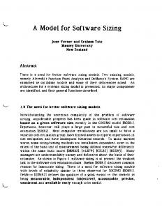
From the human point of view, features and qualities can be classified in several orthogonal ways depending on which aspect is interesting to the observer. Figure 1 shows these aspects schematically.
provides
component surface calls and events incoming, outgoing data
requires
operations
data written, read call semantics, data formats interfaces provided, required
Figure 1: Parts of software module interface A fundamental distinction is by what we call the kind. The operational features and qualities describe or are used to invoke functionality. The data features describe (sets of) data which the element exchanges with its environment. There can also be features and qualities which contain a mix of these two characteristics. An orthogonal classification attribute is the role in module interactions. Each module provides features which its clients can use to invoke its functionality and which thus represent the purpose of the module. On the other hand, the module may require the connection to some features in its environment which its implementation depends on. This distinction into roles is explicit in component-based systems [28, 20, 17] and in many modular programming languages [1, 33]. Lastly, we can differentiate features and qualities according to their usage during or applicability to different stages in module lifecycle. Current practice and research [2, 28, 15, 16] leads to several such classes: development-time for correct compilation, static or dynamic linking, and packaging (when e.g. component assemblies are created from individual pieces), design-time for the integration (or assembly) stage of creating module interconnections in a visual tool and configuring the composed application, configuration-time which covers the phase of configuring the application in the actual deployment environment, and run-time ones which are used during application execution for inter-module communication. Some features like events or data qualities, may be relevant in more phases of the lifecycle – for example provided interfaces of a CORBA component are useful in compile-time, design-time as well as run-time stages. 5
2.2
Feature and Quality Classification System
We now formalize these findings in a classification system which uses the faceted classification approach [29]. The system has, at the present stage, four facets called “dimensions” suitable for the classification of module interface features and quality attributes as described above. However, it is independent of the number of dimensions and open to further development. The term space of each facet is represented as a set of identifiers that are defined as a set Identifiers which contains strings described by the regular expression [a-zA-Z ][a-zA-Z0-9 ]*. We use a set Id spec = {nil, na, nk, any} ⊂ Identifiers of special identifiers which denote an empty value, a not applicable case, and an unknown value, and any value, respectively. The na value is used in the cases when the given dimension is not applicable to the given feature or quality. The nk value (not known) is used when the class cannot be clearly determined. The any value is used as a substitute for listing all the user-defined term values of the dimension. Definition 2.3 (ENT classification system) Let the term interface element classification system denote a faceted classification system suitable for classifying module interface elements, using a facet collection Dimensions = {dim1 , dim2 , ... , dimD } where dimi = {i|i ∈ Identifiers} ∪ Id spec . Let the term classifier denote an ordered tuple (d1 , d2 , . . . , dD ) such that di ⊆ dimi . The (core) ENT classification system is an interface element classification system which uses an ontology based on the understanding of interface elements by human users and developers, such that DimensionsEN T = {Contents, Kind, Role, Lifecycle} where • Contents = {feature, quality} ∪ Id spec is a basic dimension used to describe the primary meaning of an element, • Kind = {operational, data, mix} ∪ Id spec is a dimension describing the nature of an element with respect to computational characteristics, • Role = {provided, required} ∪ Id spec describes the “orientation” of an element in module interactions (primarily at run-time, but also important in other parts of its lifecycle), and • Lifecycle = {any, development, design, configuration, runtime} ∪Id spec is a dimension describing the possible phases in module’s lifecycle in which an element can be meaningfully accessed or used. An interface element classification system S is called an extended ENT classification system if DimensionsS ⊃ DimensionsEN T . 6
The core ENT classification system is used in this report unless noted otherwise. The extended ENT classification system may be used in situations when the core dimensions are insufficient to uniquely distinguish different interface features and quality attributes. An example is the CORBA Component Model where it is necesssary to distinguish event publishers and emitters by the arity of the event source – see [20] and Appendix A. On the other hand, there may be systems which can unambiguously distinguish interface elements using a subset of the core ENT classification. For example, the {Contents, Kind, Role} facet collection would be sufficient for the current SOFA component model.
2.3
The Model: Elements, Traits and Categories
To be able to analyze and manipulate the specification of a module interface, we need to handle the parts of the specification which correspond to the features and qualities as defined above. They describe the smallest elements of interest in our model. Definition 2.4 (Specification element) A specification element e of a module M written in language L is a tuple2 e = (name, typename, typedecl, tags, metatype, classifier ) where name ∈ Identifiers, typename ∈ Identifiers, typedecl ∈ L is a language phrase, tags = {tagi }, tagi ∈ L is a (possibly empty) set of language phrases, metatype ∈ Identifiers and classifier = (ce1 , ce2 , ..., ceD ); cei ⊆ dimi . By module specification element set EM we will understand the set of all specification elements contained in the specification of module M . In other words, EM completely represents of a module in our model. A specification element represents a complete information about one feature identified by language name and typename and/or typedecl or of one modulewide quality attribute (which may have name = nil). The tags item contains a set of phrases with additional parts of the element’s declaration. It may serve as an aid if one needs to e.g. precisely compare two elements3 , or re-generate valid source code for the element. These four parts of the specification element can be derived directly from the specification source code. Operations on them are subject to the syntax and typing rules of the language L used for module specification – in other words, this model 2
In this work, we shall denote parts of a tuple by the “dot” notation, e.g. e.classifier denotes the classifier part of a tuple e. 3 For example, in a comparison of final static int x = 5 against int x, the final static tags stored in the tags part represent an important semantic information.
7
frame AddressBook { require: /system/FileAccess files; provide: IAddressBook book; IAddressSearch search; property short maxSize; property short defaultSortOrder; protocol: // this protocol is incomplete and inaccurate, // but will do for illustration purposes ?book.addPerson { !files.create? ; !files.write } ; ( ?book.clear { !files.write } | ?book.getPerson { !files.read } | ?book.updatePerson { !files.write } )* } Figure 2: Source of a SOFA component frame with selected elements highlighted
is parametrized by the specification language for which its concrete application is sought. The metatype element is a name describing the general type of feature or quality, such as “interface” or “event”. It is often represented as a non-terminal symbol in the grammar of L. The classifier contains the classification of the element according to the ENT classification system. This information has to be provided manually, based on an analysis of the language L and the human-percieved meaning of its phrases. The purpose of such effort is to create a complete but minimal set of metatypes and classifier combinations which the specification elements can have. The motivation is their use in the description of the module’s characteristic traits (see below). Once this analysis is done, it is relatively easy to create the appropriate supplementary code in a suitable parser/analyser of the specification language L. Completeness of the element means that it includes all the information about the feature or quality attribute contained in the specification (with respect to both the language declarations and the classification dimensions) even if this information is not available in a single language phrase. For example, in SOFA CDL the interface variable belongs to either the provides or requires section but 8
maxSize name = maxSize, typename = short, typedecl = nil, tags = ∅, metatype = property, classif ier = ({feature}, {data}, {provided}, {development, design, runtime}) files name = files, typename = /system/FileAccess, typedecl = nil, tags = ∅, metatype = interface, classif ier = ({feature}, {operational}, {required}, {any}) protocol name = nil, typename = nil, typedecl = ?book.addPerson { !files.create . . . } . . . , tags = ∅, metatype = protocol, classif ier = ({quality}, {operational}, {provided, {development, design, runtime})
required},
Figure 3: Selected elements in the AddressBook SOFA component these keywords are not part of the interface variable declaration itself. Definition 2.5 (Element comparison) We say that two specification elements are equal, ei = ej iff ei .name = ej .name∧(ei .typename 6= nil∧T ypeOf (ei .typename) =L T ypeOf (ej .typename)) ∧ (ei .typedecl 6= nil ∧ ei .typedecl =L ej .typedecl) ∧ ei .tags =L ej .tags. We say that specification element ei is subsumed by specification element ej , ei < ej iff ei .name = ej .name∧(ei .typename 6= nil∧T ypeOf (ej .typename) ≺L T ypeOf (ei .typename)) ∧ (ei .typedecl 6= nil ∧ ej .typedecl ≺L ei .typedecl) ∧ ei .tags ⊂L ej .tags. The case when two specification elements have incomparable contents, i.e. ei .name = ej .name ∧ ei 6≤ ej ∧ ei 6> ej is denoted ei 4 ej in this work.
9
Note that the relations are based on the contents derived from the specification source only and are parametrized by the specification language L of the elements. We would also like to point out the reverse role of subtyping in the comparison of the .typename and .typedecl parts: the motivation is the intended meaning “ei has fewer declarations (and/or more restrictions) than ej ”. Assume e1 = (count,int, nil, ∅,. . . ), e2 = (count,int, nil, {static,final},. . . ), and e3 = (count,longint, nil, ∅,. . . ). Then, the following holds: • e1 < e2 , because ∅ ⊂ {static,final}, and • e1 > e3 , because int ≺ longint and the other parts of e1 , e3 are equal, • e2 4 e3 , because int ≺ longint but {static,final} ⊃ ∅. Figure 4: Examples of element comparison results
2.3.1
Traits in Interface Specification
As was said at the beginning of this chapter, we would like our model to handle the declarations in the module interface specification in a manner natural to our human perception. In particular this involves grouping the specification elements into more abstract concepts – characteristic traits of the module. Definition 2.6 (Trait) Let trait classifier C T be a tuple (ct1 , ct2 , ..., ctD ) where cti ⊆ dimi . A specification trait (or just trait in short) of a module is a tuple t = (name, metatype, C T , E) where name ∈ Identifiers, metatype ∈ Identifiers, and E ⊆ EM is a set of specification elements such that ∀ei ∈ E, cei ∈ ei .classifier : cei = cti ∧ ei .metatype = metatype. A module trait set is a set of traits TM = {t} such that ∀ti , tj ∈ TM : ti .name 6= tj .name and ∀e ∈ EM ∃tk ∈ TM : e ∈ tk .E. In plain words, trait is a named set of specification elements which have the same meaning as characterized by the trait definition (a unique combination of classifier s and metatype of the contained elements). Thus we can for example get traits of provided events, required interfaces, provided design-time qualities, etc., mirroring user’s view of the module. Traits group elements of a module even if in the source these may be written in various places (as shown in Figure 2 on page 8). This allows us later to analyse the interface specification by the meaning of its parts rather than by their place
10
of occurence or language type. This approach is similar to connection protocols described in [4]. We should note that not all combinations of element classification dimension values need make sense in the given specification language4 . This in practice greatly reduces the number of traits and thus the complexity of the model. For example, the SOFA system provides the component specifier with just four traits of elements shown in Figure 5. provides: metatype = interface, classifier = ({feature}, {operational}, {provided}, {any}), requires: metatype = interface, classifier = ({f eature}, {operational}, {required}, {any}), properties: metatype = property, classifier = ({f eature}, {data}, {provided}, {development, design, runtime}), and protocol: metatype = protocol, classifier = ({quality}, {operational}, {provided, required}, {development, design, runtime}). Figure 5: Trait definitions for the SOFA system Definition 2.7 (Trait comparison) Assume traits ti and tj such that ti .name = tj .name. We say that the two traits are equal (denoted ti = tj ) iff ti .E = tj .E. We say that trait ti is subsumed by trait tj (denoted ti < tj ) iff ti .E ⊂ tj .E (i.e. |ti .E| ≤ |tj .E| ∧ ∀ei ∈ ti .E∃ej ∈ tj .E : ei ≤ ej ). The case when two traits have incomparable contents, i.e. ti 6≤ tj ∧ ti 6> tj is denoted ti 4 tj . Note that, in line with the specification element equality and order, these relations are based solely on the specification contents. The human-added information is too unreliable to use it for precise relationships – namely, it is difficult to find any natural ordering of the classification facets and their terms. 2.3.2
Trait Categories
Although traits are a useful grouping of specification declarations, for an architectural level view of a module their granularity is still too small. In high-level 4
In such cases we can use partial classification like (quality, na, nk, runtime), providing as much information as practical.
11
Name Provisions Properties Requirements Protocol
Elements { (book,IAddressBook, …), (search, IAddressSearch, … ) } { (maxSize,short, … ), (defaultSortOrder,short, … ) } { (files,/system/FileAccess, … ) } {(–,?book.clear { !files.write …, … ) }
Figure 6: The traits in the AddressBook SOFA component analyses of software we often come into situations where would like to handle for example “all provided features” as a single group. Such groups are called categories in our model. Definition 2.8 (Category) A specification trait category (shortly category) of a module is a tuple K = (name, C K , T ) in which name ∈ Identif iers, C K = (ck1 , ck2 , ..., ckD ) where cki ⊆ dimi and T ⊆ TM such that ∀t ∈ T, cti ∈ t.C T : cti ⊆ cki . A category set is a set of categories {C1 , C2 , ..., Cn } such that ∀t1 ∈ Ci , t2 ∈ Cj : t1 6= t2 . That is, categories group traits which are similar in some aspect(s). This is expressed in our model by sharing the values in some of their classification dimensions while disregarding other dimensions, as specified by the category definition C K . The category set provides category definitions such that each trait from the module trait set belongs to at most one category of the set; note that the category set need not cover all specification elements of a module. F-D (Functionality-Data) C F = (Contents, {operational}, Role, Lifecycle), C D = (Contents, {data}, Role, Lifecycle) Fe-Q (Features-Qualities) C F e = ({feature}, Kind, Role, Lifecycle), C Q = ({quality}, Kind, Role, Lifecycle) S-Q (Services-Qualities, or the Server view) C S = ({f eature}, {operational}, {provided}, Lifecycle), C Q = ({quality}, Kind, {provided}, Lifecycle) Figure 7: Example category sets
12
From the definition above it follows that we can define several different category sets which, superimposed on module specification expressed in traits, can give us completely different views of the module. A key category set, the E − N − T set, is defined below. Other category sets that can be useful in the ENT model applications are shown in Figure 7 on the page before.
Figure 8: A SOFA component structured by different category sets It is worthwhile to note the subtle but important difference between trait and category definitions. Traits require that the element classifier be equal to that of the trait – for instance, that lif ecycle = development ∧ lif ecycle = runtime. Thus traits strictly split the element set into distinct subsets. Categories on the other hand group elements with classifiers that are subset of the category classifier C K – this may be e.g. written as lif ecycle = development ∨ lif ecycle = runtime. The other notable characteristic of categories is that they group elements of different meta-types. They therefore allow operations on the module specification based on its human understanding (represented by the classification system described above) rather than on the syntax or the typing system of the language. Definition 2.9 (Category comparison) Assume two categories Ki , Kj such that Ki .name = Kj .name. We say that these two categories are equal (denoted Ki = Kj ) iff |Ki .T | = |Kj .T | ∧ ∀ti ∈ Ki .T ∃tj ∈ Kj .T : ti = tj . We say that category Ki is subsumed by category Kj (denoted Ki < Kj ) iff |Ki .T | ≤ |Kj .T | ∧ ∀t1,i ∈ Ki .T ∃t2,j ∈ Kj .T : t1,i .name = t2,j .name ∧ t1,i ≤ t2,j . The case when two 13
categories have incomparable contents, i.e. Ki 6≤ Kj ∧ Ki 6> Kj is denoted Ki 4 Kj . 2.3.3
The E, N, T categories
Because categories are parametrized by classification dimensions, they add flexibility to our model. The set of categories most useful for our work surveyed in the next section is obtained by using the role dimension. This way we get three categories which also give the name to our model of module interface: exports E = (exports, C E , T E ); where C E = ({f eature}, Kind, {provided}, Lif ecycle); needs N = (needs, C N , T N ); where C N = ({f eature}, Kind, {required}, Lif ecycle); tags T = (tags, C T , T T ); where C T = ({quality}, Kind, {provided, required}, Lif ecycle). Figure 9: The ENT category set The speciality of this particular category set is that it captures the different aspects which each part of the interface (and consequently the corresponding specification trait) has from the point of view of the module interconnections. It is thus a formalization of the general idea presented in Figure 1 and a crucial structure for the definitions of compatibility presented in [9].
14
3
Applications of the Model
The model of module interface structuring presented in the preceding section is applicable to a wide range of module- and component-based systems. It is also general enough to serve different purposes, suitable for the module developers (mainly in module understanding) as well as their tools (automated module comparisons). In this chapter we briefly present these aspects of the model. As major part of the things presented is currently work in progress, they are best taken as examples motivating the development of the model.
3.1
Applicability
The examples shown in Section 2 use the SOFA component model to illustrate the concepts. This is a primary platform on which the research on the ENT model is being carried. The particular features of this framework which make it appealing to ENT are the simple and readable CDL component specification language and the presence of features and quality attributes with the key kinds and and roles. In a straightforward extension, the model is well applicable to the CORBA Component Model (CCM [20]). While CCM does not use any quality attributes in component specification, its IDL has constructs for several kinds of features. The example shown in Figure 10 on the following page shows a dissection of a CORBA component in the ENT model. Appendix A provides the definitions of traits applicable to CCM, as well as further examples. In a similar manner, other component or modularization systems which use an IDL-like language for the specification of component interface [11, 24] can utilize the ENT model. The generality of the model however makes it possible to apply its approach also to modules specified in other languages. One example is the Java platform, in particular the JavaBeans [2] component model. Using a modifed Java parser which takes into account only the interface parts of the public class constructs, we can dissect a JavaBean interface into a set of six traits – imported packages, imported classes, extended classes, implemented interfaces, methods, and properties. An example (using a simplified version of the sunw.demo.Juggler JavaBean) is shown in Appendix B. The application of the ENT model to JavaBeans suffers however from one deficiency of the platform. JavaBeans can be used in two modes – a design mode is utilized by visual tools for setting up bean interconnections, the runtime mode is a standard mode during bean-based application execution. Some methods of a bean are applicable only to the design mode, most are available only in runtime mode. The problem is that this designation is realized by testing the isDesignMode() 15
// other declarations omitted // for brevity component HTTPClient { provides HTTP connection; uses ::net::Sockets network; attribute boolean keepalive; attribute long timeout; };
Figure 10: A CORBA component in ENT dynamic property (from java.beans.DesignMode interface) inside method bodies. Unless a sophisticated analysis of method body code is used, it is impossible to correctly set the lif ecycle classification property of each method. Based on our experiences, we expect the ENT model to be applicable also to widely used modular programming languages, such as to Delphi units, Ada packages or C language modules. Again, parsing the source to find and classify elements can be complicated to a different degree. Especially the case of the C language would require a modified grammar which mixes language and preprocessor constructs (the #include directive represents the module dependencies, i.e. elements with role = required classification). Some of these problems are highlighted in Section 4 at the end of this report.
3.2
Use for Humans
The ENT representation of software modules and components can be helpful in human understanding of the software. This is a direct result of the design of the model achieved mainly via its classification system. The three levels of interface structuring – elements, traits and categories – can show the interface in different levels of detail and in various views oriented towards different aspects. Figure 8 on page 13 shows how this can look like. The aim of this feature of the model is to provide for easier and less error prone software evaluation, thus facilitating tasks such as visual design, re-engineering and maintenance. The primary envisaged application in this respect is in visual design tools. The use of the ENT model in this context would result in software presentation in user terms rather than (as common now) in language terms. Especially for visual development with components, the developer can then 16
have the component appearance affected by category selection. Such view parametrization can have three applications: 1. In assembly (binding) of modules into applications, e.g. in solving the tasks “now I want to see just the links between the provided and required ifaces” in CORBA components, or “let’s see how events propagate” by showing just event sinks/sources with event names. 2. In search/evaluation, the model can provide a tree view of a single component in which the user can expand category, trait, and specification item contents to trace down a particular feature. For example, in seaching for the animationRate property of the Juggler JavaBean, the developer would use the Operational-Data categories and unfold, in sequence, the “Data” category and the “Properties” trait, to find the specification. 3. In maintenance or servicing, the maintainer can test change propagation in “what-if” scenarios using the role of features (see Figure 11) – change is OK if the proposed modification is an extension of the provided or a reduction of the required features.
Figure 11: Change propagation shown in the ENT model Another use is in library search and retrieval, where the model can assist in narrowing the result set. This can be achieved by augmenting the search methods (e.g. fulltext search in descriptions, signature matching, etc.) using the classifiers and other metadata associated with elements, traits and categories. The user can, for example, restrict the search for a SOFA component to match just signatures of the provided operational features (within interfaces in the provides trait). 17
3.3
Use for Tools
In the area of tool-based module and component processing, the ENT model can provide support for automated component evaluation. The unique and interesting feature in this respect is the possibility to represent in the same format the interface of modules from different systems. This opens the opportunity for side-by-side comparison, high-level analyses and other processing. In particular, we currently use this approach in two different but related scenarios. First, we can produce a meaning-based diff of two modules (see Figure 12). This is useful in the evaluation of module or component substitutability [9], as well as in tracing change propagation as described above.
Figure 12: ENT -based difference highlighting Secondly, the results of this ENT -based diff are the input data in our languagebased revision identification of SOFA and CORBA components [7, 8]. This approach uses a structure of the revision number based on the E , N , T category set, rather than an M .m.µ scheme with arbitrary semantics. From a wider perspective, the low-level ENT data could also be used e.g. for translation of module interfaces between systems. For example, after extracting ENT data for a JavaBean component we could use this data to generate a CORBA IDL skeleton of a corresponding CCM component. The assistant role in library search and retrieval mentioned in the preceding subsection obviously needs related automated support. We also expect that the ENT model could be beneficial for component testing, as identificaiton of 18
traits/categories allows separate testing of independent aspects (functionality vs. QoS tests). The generality of the ENT model suggests that more uses of it can be found.
19
4
Discussion
The purpose of creating models is to abstract away details of the subject which are not interesting from the particular point of view. Therefore, care must be taken to balance simplicity and precision in the model definition. The subject of our work, software module and component systems, exhibit a great degree of variation. Thus the goal of our work may be noble but is not easy to attain. In this section, we would therefore like to discuss in more detail the model, its advantages and weaknesses. This opens the way for further work on applications and improvements of the model, as well as in related areas.
4.1
Advantages of the Model
The primary objectives of the model are conceptual simplicity and close correspondence to human (primarily developer’s) view on software modules. These aspects can be directly counted as the module’s advantages. The simplicity lies primarily in the use of a restricted set of classification facets and metadata items attached to interface elements, and in straighforward rules for their grouping into traits and categories. The model should thus be easy to comprehend and implement in code. The application of the model to a given module-based programming language or component framework results in a representation of modules or components that is easy to visualise and comprehend. This stems from the selection of classification facets and from the natural hierarchy of elements, traits and categories. The model is thus a contribution to the area of program understanding. Additionally, the model allows to manipulate the software specification (analyse, compare, transform) based on interesting semantic properties. While these properties are not always directly expressed in the syntax of the language, it is relatively easy to augment the given parser to extract them. Furthermore, the model hints the possible improvements in specification languages (see Appendix C on page 33). The model was designed to be very general and independent of any particular technology or specification language. It is thus and applicable to many research and industrial platforms – among others to SOFA [28], C2 [24], CORBA [20], JavaBeans [2] and Enterprise JavaBeans [3]. Examples of an ENT model of CORBA and JavaBean components are given in the Appendix. As the definition of trait and category is not bound to a predefined classifier, the model allows to flexibly define ENT-based software representations for various purposes. The main practical application is the ability to reduce the specification to an “interesting” subset (e.g. to the provides part of the component interface) depending on the concrete interests of the users. 20
Finally, the model is open for extensions. It was noted in Section 2 that the facet collection used in ENT classification is not fixed. Should the analysis of platforms, frameworks and languages not covered by our research reveal new classification dimensions, they can be added without directly affecting the model itself. Similarly, the ordering relations for specification elements can be changed, e.g. using the approach to relaxed signature matching presented by Zaremski and Wing [36].
4.2
Disadvantages and Open Issues
The ENT model presented here has however several shortcomings that need the attention in future research. The primary problem as we see it is the need for manual classification of specification elements in the given language. This need arises because automated classification is in general a difficult problem [6, 36], in this case further complicated by the lack of expressiveness of some specification and programming languages. This opens room to different interpretations and thus imprecise classification of features and properties (e.g. along the Lif ecycle dimension). The second problem concerns the fact that elements are taken as atomic units without considering the details of their internal structure. For example, in the element property: readonly int count; the keyword readonly expresses mainly semantics of the property but this information is largely disregarded in the current model. Similar case are methods in Eiffel [21] with pre- and post-condition expressions. This calls for a more accurate handling of the tags part of the specification element. The desired effect would be achieved by defining this part as a set of pairs tags = {(declarations, classif ier)}, i.e. tagging individual parts of the declaration with classifiers. This would make the model match reality better but at the expense of readability and simplicity. We therefore accept the simpler approach and consider declarations as monolithic, classified by its overall proximity to the classification facet terms. The use of internal structuring of declarations is reserved for future work. Last but not least, the implementation of the ENT model for some languages requires non-trivial amount of work. In some cases it is necessary to redesign the language grammar so that elements and traits are easier to separate. In any case the approach depends on the creation of suitable parsers which extract the relevant data from the specification source. These two tasks combined pose a challenge mainly in the case of syntactically rich programming languages like C/C++ or Java.
21
4.3
A Note on Specification Languages
There are however a few problems outside of the model, in specification languages themselves, which may hinder the full use of our approach to interface structuring. The most unfortunate one is the lack of expressiveness of current specification languages. For example, while the support for the provides role is common, only several research and a few industrial languages allow to specify required features [28, 20]. Similarly, the languages allow the specification of only a limited number of data feature types. The only common one are data properties, but in reality software components often depend on or create various data files and streams. No component framework in widespread use provides support for file or stream specifications that would capture this important aspect of their functionality. The result is that the model presented in this paper can easily accomodate today’s specifications but is not used to its full potential. Thus our reasoning about features and properties provides hints on what can (and should) be done in terms of improving component specifications. Appendix C on page 33 shows how we envision a component specification with some of these aspects implemented.
22
5
Related Work
Component models. In the area of component models, there exists several widely known research and industrial systems. Some of them (C2 [24], SOFA [28], CORBA [20]) provide a reasonable component model which uses interface specification language (under various names – ADL, IDL, CDL) with syntactic distinction of provided and required parts of the interface. In some cases, a form of semantic properties specification is also available. There are also other frameworks (e.g. COM [11], EJB [3]) which do not match our general model too well but are interesting due to their widespread practical use. However, there seems to be a lack of explicit work on modeling module and component interfaces [25, 19]. The notion of module-based programming [26] first introduced the concept of information hiding and the separation between interface and implementation in software. This is now taken as one of the fundamental principles in software engineering and in the pure form is represented by the systems which use various IDL-like languages [13, 27, 32]. There are several languages representing the module-based programming paradigm that are interesting from our point of view. First, the Ada programming language [1] provides very rich and precise means for specifying module and class interfaces. The Eiffel language [21] is interesting from the point of view that its class declarations can contain semantic properties in the form of pre- and post-condition plus class invariant. Also, the Eiffel compiler set includes a tool to generate a digest form of class declaration which is close to the specification languages mentioned above. Among the languages that are more common in practical use, we might mention Java with its javadoc tool that can be used to generate a documentation of the interface to public elements in the class declaration. Feature classification. The ENT model uses an (admittedly simple) faceted classification system first introduced to software by Prieto-Diaz [29]. However, the main inspiration comes from the implicit classification of features (keywords like provides, imports, etc.) found in some IDL languages [20, 28, 24] Specification analysis. There are several works which deal with the analysis of software source code, be it interface specification or the implementation code. Medvidovic and Taylor [19] mention in this respect mainly enforcement of properties, simulation and code generation. Zaremski and Wing [36] extract method signatures from Standard ML code and then apply various forms of their matching in a library search approach. CASE tools (e.g. Together [35], Rational Rose [30]) usually support so-called “round-trip engineering” where source code can be generated from an UML model, modified and then parsed to re-create the model. Software visualization. Most component-based systems support some form 23
of visual design mode in which components represented as elements without internal structure can be interconnected. However as Medvidovic [19] notes “support for other views is sparse”. The UML notation [14] is a widely used graphical language for visualising static and dynamic aspects of object-oriented systems. The visual representation of the modules shown in the examples in Section 2 is inspired by the UML approach but goes further in the possibility to collapse individual levels (categories, traits, elements) and to parametrize the display by the category set used. In the area of software comprehension, the work on visualizing change propagation (see e.g. [10]) touches a topic related to our work. The use of the ENT model can bring the benefit of separating dependencies between individual traits, allowing to focus on change propagation only in particular aspects.
24
6
Future Work
The work on the ENT model is done mainly to support other areas of our research related to component compatibility and versioning [8, 9]. However, there are several opportunities for work connected to the model itself. They are listed below in no particular order. First, it would be beneficial to verify the model on a wider range of modular programming languages, component frameworks and specification languages. The main purpose of this expected work is to verify the structure of the specification element and the choice of classification dimensions. Among the candidate systems are the Wright language [5], the C2 ADL [24], Enterprise JavaBeans [3], Ada language packages [1], Eiffel classses [21] and Borland Delphi [33] components. As noted in the discussion above (Section 4), one of the shortcomings of the model is the uniform treatment of element declaration parts. It would be more appropriate to provide element comparison which uses tag matching rather than set comparison of the tags set. This will therefore be subject to the investigation of possibilities and methods. Preliminary practice shows, that the design of an ENT model for a particular language does not start with determining interface elements and classifying them according to the classification scheme. Instead, it is easier to start directly with the language grammar and find rules describing specification traits. The interface elements are then extracted from the specification source using the appropriate parser. This suggests that the definition of trait based on element classification (as given in Section 2.3.1 on page 10) may be too restrictive and/or complicated for practical use. Therefore, we will study the relationship between elements and traits in more detail. To support automated ENT data extraction, more research into the possibilities of grammar tagging is needed. The purpose of this work is to tag specification language grammar rules to indicate, whether the rule contributes to a particular element, trait, or their class. Such grammar tagging would enable us to automatically generate ENT parsers or at least their skeletons, thus eliminating the most mundane work on the model implementation. The possibility to visualise the module’s ENT representation opens the way to further research its possible use in software visualisation, comprehension and modeling. While there exist various notations and approaches in this area that help software developers the ENT model can add the possibility to parametrize the visual representation by chosen category set. This may be interesting e.g. in relation to showing version differences or change propagation [10]. There is also need for more work in the implementation of the model as presented in this paper. First, the support for SOFA component framework should 25
be completed. This involves automatic generation of ENT data from SOFA CDL source (CDL parser, XML output backend), visualisation of the components from ENT data parametrized by trait and category definitions. The latter should also include interconnections with the option to show change propagation effects. A part of this work is currently in progress. Second, the metod for comparison of ENT data to generate an ENT diff should be fully specified and implemented, together with generating revision identification as described in [8] based on the diff results. In correspondence with the visualisation aspect of the model, the visual display of this diff should be implemented. Lastly, our aim is to provide an example implementation of the ENT-based representation, comparison and revision identification for the CORBA Component Model. At present the component versioning part is under development.
26
7
Conclusion
In this report we have presented a general model for natural structuring of the interface of software modules and components, motivated by the need to to enable analyses based on user understanding of the software. The model uses a faceted classification of interface features and properties derived from their various aspects as perceived by human developers and users. The resulting structuring of interface into, among others, the exported and needed elements formalizes the notion of software component as defined by Szyperski [34]. The key feature of the model is its extensibility and applicability to different component- and module-based systems. While being general enough to cover most current systems, it can easily accomodate future developments by extending the classification system and/or enhancing the comparison methods used. As it is not tied to a concrete system it may serve, among other uses, as a unifying platform for software visualization. Our subsequent work on the model will be mainly driven by the needs to further improve some aspects of the model, mainly in order to make it more precise in modeling detailed aspects of the interface. Also, several applications of the model will be explored together with a research into techniques facilitating further automation.
27
A A.1
The ENT model for CORBA components Trait Definitions
The CORBA Component Model requires to use an extended classification system that enables us to distinguish event publishers and emmiters: DimensionsCCM = DimensionsEN T ∪ {Arity} where Arity = {single, multiple} denotes how many connections an element can accept/provide. inherits metatype = component-ref, classifier = ({feature}, {operational, data}, {provided}, {development}, {na}) supports metatype = interface-ref, classifier = ({feature}, {operational}, {provided}, {any}, {na}) facets metatype = interface-ref, classifier = ({feature}, {operational}, {provided}, {any}, {nk}) receptacles metatype = interface-ref, classifier = ({feature}, {operational}, {required}, {any}, {single, multiple}) publishers metatype = event-ref, classifier = ({feature}, {operational}, {required}, {any}, {multiple}) emitters metatype = event-ref, classifier = ({feature}, {operational}, {required}, {any}, {single}) sinks metatype = event-ref, classifier = ({feature}, {operational}, {provided}, {any}, {single, multiple}) attributes metatype = attribute, classifier = ({feature}, {data}, {provided}, {design}, {na})
A.2
Example: The Parking Component Source
The source (from OpenCCM [18] examples): // the parking. component Parking { // parking states. readonly attribute string description; 28
readonly attribute ParkingState state; readonly attribute PlaceNumber capacity; readonly attribute PlaceNumber free; // parking receptacles. provides ParkingAccess for barriers; provides ModifyState for admin; // parking events ports. publishes ChangeState state notify; };
A.3
Example: The Parking Component in ENT
The representation of the Parking component in traits is as follows, ommitting empty traits and element classifiers. facets = {(for barriers, P arkingAccess, ∅, ∅,interface-ref , (. . . )), (for admin, M odif yState, ∅, ∅,interface-ref , (. . . ))} publishers = {(state notify, ChangeState, ∅, ∅,event-ref , (. . . ))} attributes = {(description, string, ∅, {readonly},atribute, (. . . )), (state, P arkingState, ∅, {readonly},attribute, (. . . )), (capacity, P laceN umber, ∅, {readonly},attribute, (. . . )), (f ree, P laceN umber, ∅, {readonly},attribute, (. . . ))}
29
B
The ENT Model for JavaBeans
We ought to note in this place that it is not easy to create the trait definitions for JavaBean components [2]. The primary reason is the way the component model is defined – namely, the excessively close links to the Java language type system and to a set of name conventions (the specification refers to these as “design patterns” which is a misnomer). In the first place, to find elements of the properties trait, the syntactical analysis of method signatures must be complemented by the appropriate lexical analysis of their names. This is because JavaBean properties are implemented as pairs of accessor and mutator methods that are named according to a convention. For example, to define a property int property, a JavaBean must contain methods int getProperty(); plus void setProperty(int value);. Next, the JavaBean model contains an event-handling mechanism using the publish-subscribe design pattern. However, this is realized by JavaBean classes implementing listener interfaces which group event declarations. If we were to define a trait for the events a component can react to, we would have to refer to the contents of such interfaces which is obscure at the conceptual level and difficult for the implementation. The most we could do is to rely on another name convention as listener interface names should end in Listener – but this method is highly unreliable because the name convention is not mandatory. We could also try to detect eventhandling methods in component interface – but the “design pattern” by which they are described in the specification (void ( evt);) is clearly so general that it is useless for any automated analysis.
B.1
Trait Definitions
The JavaBean framework uses the core ENT classification system. As noted in Section 4, it is not possible to distinguish design-time and run-time methods based on method signatures only. imports-p metatype = CanonicalPackageName, classifier = ({feature}, {nk}, {required}, {development}) imports-c metatype = CanonicalClassName, classifier = ({feature}, {operational, data}, {required}, {development}) extends metatype = ClassName, classifier = ({feature}, {operational, data}, {required}, {development})
30
implements metatype = InterfaceName, classifier = ({feature}, {operational}, {provided}, {any}) methods metatype = Method, classifier = ({feature}, {operational}, {provided}, {runtime}) properties metatype = Property, classifier = ({feature}, {data}, {provided}, {design, runtime})
B.2
Example: The MyJuggler JavaBean Source
The following code is an shortened version of the original sunw.demo.Juggler JavaBean. The method bodies are removed due to the fact they are not interesting in interface specification. Several specification elements are highlighted in the code. package zcu.fav.kiv.ent.demo; import import import import import import
java.awt.*; java.awt.event.*; java.awt.image.*; java.net.URL; java.beans.*; java.beans.DesignMode.*;
public class MyJuggler extends Applet implements PropertyChangeListener, DesignMode { /** design time methods */ public void setDebug( boolean debug) { /* ... */ } /** property: int animationRate */ public int getAnimationRate() { /* ... */ } public void setAnimationRate(int x) { /* ... */ } /** Juggler methods */ public synchronized void startJuggling() { /* ... */ } public synchronized void stopJuggling() { /* ... */ } public void startJuggling(ActionEvent x) { /* ... */ } 31
public void stopJuggling(ActionEvent x) { /* ... */ } public boolean isJuggling() { /* ... */ } /** administrative methods */ public void setDesignTime(boolean dmode) { /* ... */ } public boolean isDesignTime() { /* ... */ } public boolean isDebug() { /* ... */ } }
B.3
Example: The MyJuggler JavaBean in ENT
The representation of the MyJuggler JavaBean in traits is as follows, ommitting the metatypes and classifiers. imports-p = {(nil, java.awt, ∅, ∅,. . . ), (nil, java.awt.event, ∅, ∅,. . . ), (nil, java.awt.iamge, ∅, ∅,. . . ), (nil, java.beans, ∅, ∅,. . . ), (nil, java.beans.DesignM ode, ∅, ∅,. . . )} imports-c = {(nil, java.net.U RL, ∅, ∅,. . . )} extends = {(nil, Applet, ∅, ∅,. . . )} implements = {(nil, P ropertyChangeListener, ∅, ∅,. . . ), (nil, DesignM ode, ∅, ∅,. . . )} methods = {(setDebug, boolean → void, ∅, ∅,. . . ), (startJuggling, void → void, ∅, {synchronized},. . . ), (stopJuggling, void → void, ∅, {synchronized},. . . ), (startJuggling, ActionEvent → void, ∅, ∅,. . . ), (stopJuggling, ActionEvent → void, ∅, ∅,. . . ), (isJuggling, void → boolean, ∅, ∅,. . . ), (setDesignT ime, boolean → void, ∅, ∅,. . . ), (isDesignT ime, void → boolean, ∅, ∅,. . . ), (isDebug, void → boolean, ∅, ∅,. . . )} properties = {(animationRate, int, ∅, ∅,. . . )}
32
C
Vision of a Rich Component Specification
The following IDL-like code shows how we envisage a full-featured component specification, using the experiences gained in developing the ENT model described in this paper. The notable enhancements agains current IDL/ADL languages are: • Explicit declaration of data features like files and streams, including means for datatype and/or format specification of their records. • Use of annotations to describe semantic, classification and quality of service properties of individual elements as well as of the whole component. • The ability to include versioning information in the component IDL specification.
dataformat LogFile [ascii] { DateTime date; String object; int result; } component ExampleCo [remote rev=3.1.1] { provides: InterfaceA a1 [rev=4.1 synchronized arity=1]; InterfaceB b1 [arity=any bind-after=a1] [* response-time:avg=1ms,max=30ms *]; LogFile log [filename=SystemLogDir."ExampleCo.log"] [* growth-rate-avg=230 *]; requires: InterfaceX x1 [rev-from=2.0 rev-to=3.3 synchronized]; ConfigFile cfg [filename=SystemConfigDir."ExampleCo.cfg" read-write]; properties: int MAX = 256 [design-time run-time]; String WindowTitle [design-time]; String SystemLogDir = "/var/log/"; String SystemConfigDir = "/etc/components/"; state: 33
int count; float[] data; invariant: count >= 0 and count < MAX; protocol: { log.open ; cfg.read } ; ( ?a1.a { !x1.a ; log.write } || ?a1.b { !x1.a ; !x1.b ; log.write } ) + ?b1.q ; { log.close } }
34
References [1] Ada 95 Reference Manual : Language and Standard Libraries. Lecture Notes in Computer Science 1246. Springer Verlag, November 1997. International Standard ISO/IEC 8652:1995(E). [2] JavaBeans (version 1.01). API specification, Sun Microsystems, Inc., 1997. [3] Enterprise JavaBeans(TM) Specification. Version 2.0, Sun Microsystems Inc., August 2001. [4] Mar´ıa Jos´e Presso. Declarative Descriptions of Component Models as a Generic Support for Software Composition. Position paper, June 2000. Workshop on Component-Oriented Programming (WCOP’00). [5] R. Allen and G. Garlan. Formalizing architectural connection. In Proceedings of the Sixteenth International Conference on Software Engineering, pages 71–80, Sorrento, Italy, May 1994. [6] Juergen B¨orstler. Feature-oriented classifciation for software reuse. In Proceedings of the 7th International Conference on Software Engineering and Knowledge Engineering, pages 204–211, Rockville, MD, USA, Jun 1995. [7] Pˇremysl Brada. Component change and version identification in SOFA. In Jan Pavelka and Gerald Tel, editors, Proceedings of SOFSEM’99, LNCS 1725, Milovy, Czech Republic, 1999. Springer-Verlag. [8] Pˇremysl Brada. Component revision identification based on idl/adl component specification. In Proceedings of the Xth European ACM Conference on Software Engineering (ESEC/FSE). ACM Press, 2001. [9] Pˇremysl Brada. Towards automated component compatibility assessment. Technical report, Budapest, Hungary, 2001. Presented at the Workshop on Component-Oriented Programming, WCOP’2001 affiliated with ECOOP’2001. [10] Kunrong Chen and V´aclav Rajlich. Ripples: Tool for change in legacy software. Technical report, Department of Computer Science, Wayne State University, Detroit, MI, 2001. [11] Microsoft Corporation and Digital Equipment Corporation. The component object model specification. Draft version 0.9, Microsoft Corporation, October 1995.
35
[12] M. Goedicke and H. Schumann. Component-oriented software development with Π. ISST report 21/94, Fraunhofer Institute for Software-Engineering and Systems Engineering, 1994. [13] Object Management Group. The Common Object Request Broker: Architecture and Specification (Revision 2.4.2). OMG Document formal/01-02-33, OMG, February 2001. [14] Object Management Group. The Unified Modeling Language v1.4. Omg standard, OMG, 2001. [15] Magnus Larsson and Ivica Crnkovic. New challenges for configuration management. In Proceedings of the SCM-9 workshop, ECOOP 1999, LNCS 1675, Toulouse, France, Sep 1999. [16] Chris L¨uer and David S. Rosenblum. Component-Based Development, 2001.
WREN—An Environment for
[17] J. Magee et al. Specifying distributed software architectures. In Proceedings of ESEC’95, Barcelona, Spain, 1995. [18] Raphael Marvie, Philippe Merle, and Mathieu Vadet. The OpenCCM platform. http://corbaweb.lifl.fr/OpenCCM/index.html, 2001. [19] Neno Medvidovic. A Classification and Comparison Framework for Software Architecture Description Languages. Technical report UCI-ICS-TR97-02, University of Carolina, Irvine, 1997. [20] Philippe Merle. CORBA 3.0 New Components Chapters. OMG Document ptc/2001-11-03, Object Management Group, November 2001. [21] Bertrand Meyer. Eiffel: The Language, 2nd ed. Prentice Hall, 1992. [22] Sun Microsystems. javadoc - The Java API Documentation Generator, 2002. [23] M.T.Peterson. DCE: A Guide to Developing Portable Applications, chapter 17: UUID and Version attributes. McGraw-Hill, 1995. [24] Peyman Oreizy. Issues in the Runtime Modification of Software Architectures. Technical report TR-96-35, University of Carolina, Irvine, 1996. [25] Allen Parish, Brandon Dixon, and David Hale. Component based software engineering: A broad based model is needed. Technical report, The University of Alabama, Tuscaloosa, AL, USA, Apr 1999. 36
[26] David L Parnas. On the criteria to be used in decomposing systems into modules. Communications of the ACM, December 1972. [27] M. T. Peterson. DCE: A Guide to Developing Portable Applications. McGraw-Hill, 1995. [28] Frantiˇsek Pl´asˇil, Duˇsan B´alek, and Radovan Janeˇcek. SOFA/DCUP: Architecture for Component Trading and Dynamic Updating. In Proceedings of ICCDS’98, Annapolis, Maryland, USA, 1998. IEEE CS Press. [29] R. Prieto-Diaz and P. Freeman. Classifying software for reusability. IEEE Software, 18(1), Jan 1987. [30] Rational Software. Rational Rose. http://www.rational.com/products/rose/. [31] Ralph Reussner. The Use of Parametrised Contracts for Architecting Systems with Software Components. Position paper, June 2001. Presented at the Workshop on Component-Oriented Programming, WCOP’2001, Budapest, Hungary. [32] D. Rogerson. Inside COM. Microsoft Press, 1997. [33] Borland Software Corporation. Delphi 6 Developer’s Guide, 2001. [34] Clemens Szyperski. Component Software. ACM Press, Addison-Wesley, 1998. [35] TogetherSoft Corporation. Together ControlCenter 6.0 User Guide, 2002. http://www.togethersoft.com/products/controlcenter/. [36] Amy Moormann Zaremski and Jeanette Wing. Specification matching of software components. ACM Transactions on Software Engineering and Methodology, 6(4), October 1997.
37