Δt. 2c˜γ. B n+1 p. )2. ] ,. (3) where ms and qs are the mass and charge of the species s respectively and Ep and Bp are the electric and magnetic field acting on ...
Procedia Computer Science Volume 51, 2015, Pages 1178–1187 ICCS 2015 International Conference On Computational Science
The Formation of a Magnetosphere with Implicit Particle-in-Cell Simulations Ivy Bo Peng1 , Stefano Markidis1 , Andris Vaivads2 , Juris Vencels1 , Jorge Amaya3 , Andrey Divin4 , Erwin Laure1 , and Giovanni Lapenta3 1
3
HPCViz Department, KTH Royal Institute of Technology 2 Swedish Institute of Space Physics, Uppsala, Sweden Department of Mathematics, Centre for Mathematical Plasma Astrophysics (CmPA), KU Leuven 4 St. Petersburg State University, St. Petersburg, Russia
Abstract We demonstrate the improvements to an implicit Particle-in-Cell code, iPic3D, on the example of dipolar magnetic field immersed in the flow of the plasma and show the formation of a magnetosphere. We address the problem of modelling multi-scale phenomena during the formation of a magnetosphere by implementing an adaptive sub-cycling technique to resolve the motion of particles located close to the magnetic dipole centre, where the magnetic field intensity is maximum. In addition, we implemented new open boundary conditions to model the inflow and outflow of plasma. We present the results of a global three-dimensional Particle-in-Cell simulation and discuss the performance improvements from the adaptive sub-cycling technique. Keywords: Particle-in-Cell, Particle Methods, Particle Movers, Magnetosphere, Multi-Scale Simulations
1
Introduction
A magnetosphere is a region of space filled with plasma around a planet with a dipolar magnetic field. The magnetosphere magnetic field shields the planet from the incoming solar wind particles, protecting the life on the planet. The interaction between the solar wind and Earth’s magnetosphere can affect human health, disrupt communications and power grids and even damage satellites. Thus it benefits not only the science community but also the society and economy to accurately model the dynamics and to predict adverse events. The shape of a magnetosphere is determined by the microscopic interaction phenomena between the solar wind and the dipolar magnetic field of the planet. To describe these interactions correctly, we need to model phenomena occurring over a large range of time and spatial scales. In fact, magnetosphere comprises regions with different particle densities, temperatures and magnetic field intensities, where the characteristic time scales (plasma period, electron and ion gyro period) and spatial scales (Debye length, ion and electron skin depth) vary considerably. 1178
Selection and peer-review under responsibility of the Scientific Programme Committee of ICCS 2015 c The Authors. Published by Elsevier B.V. �
doi:10.1016/j.procs.2015.05.288
The Formation of a Magnetosphere with Implicit Particle-in-Cell Simulations
Ivy B. Peng et al.
In this work, we address the problem of modelling multi-scale phenomena during the formation of a magnetosphere by improving an implicit Particle-in-Cell (PIC) code, called iPic3D [7]. The implicit PIC method implicitly discretizes in time the Maxwell’s equations and particle equations of motion. The implicit PIC method allows for a simulation time step and a grid spacing much larger than those allowed in explicit PIC method. This is particularly important in the global simulation of magnetosphere, where large systems need to be simulated and the severe numerical stability constraints of explicit PIC methods need to be avoided. Several simulations of magnetosphere using explicit PIC codes are reported in Refs. [3, 8, 4, 1]. We developed a new relativistic particle mover with adaptive sub-cycling to resolve in time the fast gyration of particles located in strong dipolar magnetic field. We also implemented new open boundary conditions to mimic the inflow and outflow of the plasma into/out from the simulation box. We present the simulation results of the formation of a magnetosphere. We report the performance improvement from the adaptive sub-cycling technique used in the new relativistic particle mover. Compared to the relativistic particle mover using a fixed number of sub-cycles, the adaptive sub-cycling technique showed approximately five times speedup with the same configuration set up of the simulation reported in this paper. When realistic ion-to-electron mass ratio is used, the tests showed a typical 19 times speedup. The paper is organized as follows. Section 2 presents the implicit PIC method, the adaptive sub-cycling method and the open boundary conditions. Section 3 describes the results of the implicit PIC simulation of the formation of a magnetosphere and the performance of the particle mover using adaptive sub-cycling. The conclusions and future plans are presented in Section 4.
2
Implicit Particle-in-Cell Simulations
One of the most successful approaches to simulate space plasmas is the Particle-in-Cell method. This numerical technique uses a statistical sample of computational particles to represent the initial plasma distribution function, which is related to the probability of finding a particle with a certain velocity at a given position. The distribution function evolves by updating the particle position xp and velocity vp at each computational cycle. In implicit PIC simulations, the particle velocity and position at time n + 1 are calculated as follows [9]: ⎧ v ¯p (γ n+1 + γ n ) − γ n vpn ⎨ n+1 vp = , (1) γ n+1 ⎩ n+1 xp = xnp + v ¯p Δt � ¯p is calculated as follows: where the Lorentz factor γ = 1/ 1 − vp2 /c2 and the average velocity v ˜ p = γ n vpn + u ˜p + u v ¯p =
qs Δt n+1 E , ms 2 p
� � � ˜p ˜ p n+1 qs Δt u qs Δt u n+1 B × Bn+1 B + p p p ms 2c γ˜ ms 2c γ˜
, � �2 � qs Δt n+1 Bp γ˜ 1 + ms 2c˜ γ
(2)
(3)
where ms and qs are the mass and charge of the species s respectively and Ep and Bp are the electric and magnetic field acting on the particle at the position xp . PIC method calculates these quantities by the interpolation technique. The simulation domain is discretized into a computational grid. The electric field Eg and magnetic field Bg on each grid node g are calculated by discretizing the Maxwell’s equations on the grid and solving the resulted system. 1179
The Formation of a Magnetosphere with Implicit Particle-in-Cell Simulations
Ivy B. Peng et al.
The quantities Bp and Ep are then calculated from Bg , Eg by interpolation functions W (xg −xp ) (typically spline functions [2]): Ep =
g
Eg W (xg − xp )
,
Bp =
g
Bg W (xg − xp )
(4)
In our implicit PIC code, we calculate Eg by solving the following equation: (I + μn ) · En+1 − (cΔt)2 (∇2 En+1 + ∇∇ · (μn · En+1 )) = En + cΔt(∇ × Bn −
4π ˆn J ) − (cΔt)2 ∇4π ρˆn , c
(5)
where I is the identity matrix and μ is called implicit susceptibility for similarity of Eq.(5) to the field equation in dielectric media, and it is defined as: n Δt)2 Π(Ωns Δt μn · = ns μns · , μns · ≡ 12 (ωps (6) 2 )· Πns (Ωns Δt 2 )· is a tensor transformation: ⎡ 2 n n Δt 2 n n Δt 2 ⎤ Ωnsz Δt −Ωnsy Δt 1 + (Ωnsx Δt 2 ) 2 + Ω s x Ω sy ( 2 ) 2 + Ω sx Ω sz ( 2 ) 2 n n Δt 2 ⎦ ⎣ −Ωns Δt + Ωns Ωns ( Δt )2 1 + (Ωnsy Δt Ωnsx Δt . 2 2 ) 2 + Ω sy Ω sz ( 2 ) z 2 x y n Δt n n Δt 2 n Δt n n Δt 2 n Δt 2 Ω sy 2 + Ω sx Ω sz ( 2 ) −Ωsx 2 + Ωsy Ωsz ( 2 ) 1 + (Ωsz 2 ) � q s Bn Ωs ≡ ms c and ωps = (4πρs qs )/ms are the gyrofrequency vector and plasma frequency for ˆ quantities are expressed by: species s (i.e. electrons, ions, heavy ions, ...). The ρˆ and J ˆ , J ˆ = Π · (Jn − Δt ∇ · P n ) ρˆ = ρn − Δt∇ · J (7) 2
The solution of Eq(7) requires the knowledge of charge density ρ, current density J and pressure P on each grid cell. Again, these values can be computed by the interpolation technique: particle quantities are interpolated to calculate field values on the grid: ρs,g =
N s
p=1 qs W (xg
− xp ),
Js,g (r) =
N s
p=1 qs vp W (xg
− xp ),
Ps,g (r) =
N s
p=1 qs vp vp W (xg
− xp )
(8)
After the electric field is calculated, the magnetic field can be computed by the Faraday’s Law: Bn+1 = Bn − cΔt∇ × En+1 .
(9)
The magnetic field in the simulations of magnetospheres is the sum of a varying magnetic field Bint calculated from the above equations and a fixed dipolar magnetic field Bext . The dipolar magnetic field is aligned with z axis and centered at (x0 , y0 , z0 ). For a point at location (x, y, z), the imposed dipolar magnetic field is calculated by: Bext = − Br0 R 5
3
�
� 3(x − x0 )(z − z0 )ˆ x + 3(y − y0 )(z − z0 )ˆ y + (2(z − z0 )2 − (x − x0 )2 − (y − y0 )2 )ˆ z (10)
where R is the planet radius, B0 is the magnetic strength measured at the equator and r = � (x − x0 )2 + (y − y0 )2 + (z − z0 )2 . Bext inside the planet is set to zero.
2.1
Adaptive Sub-Cycling
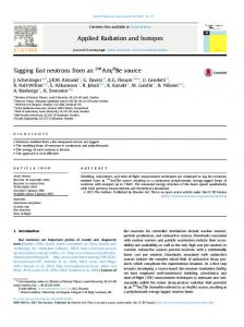
We introduce the sub-cycling method in the particle mover to correctly describe the motion of particles located near the magnetic dipole centre, where the magnetic field intensity is maximum. Particles located close to the magnetic dipole gyrate at a much higher frequency than the particles of the solar wind. To address this difference in gyration frequency, we devised a method to automatically select the number of sub-cycles depending on the magnetic field acting that particle. The sub-cycling technique divides the simulation time step Δt into smaller time step Δtsubcycle . The equation of motion is then calculated for each Δtsubcycle while the electric and magnetic field remain fixed. As shown in Figure 1a, the smaller time step is chosen to be one eighth of the gyro period T of the particle, which is calculated from the local magnetic field Blocal imposing on that particle. We determine Blocal by interpolating the magnetic field at the 1180
The Formation of a Magnetosphere with Implicit Particle-in-Cell Simulations
Ivy B. Peng et al.
computational grid nodes where the particle is enclosed in. The gyro period is then calculated 2π , where the electron gyrofrequency Ωe = eBlocal /me c. The number of sub-cycles as T = Ω e #subcycles = 4ΔtΩe /π. By using adaptive sub-cycling, it is possible to resolve in time the fast motions that cannot be resolved by the simulation time step and to save computation cost by using large time step for the particles that gyrate slow. The relative speedup by the adaptive sub-cycling is reported in Section 3.2.
2.2
Boundary Conditions
For simulations of the formation of a magnetosphere, we have implemented new boundary conditions to mimic the injection of solar wind and the exit of plasma from the simulations box. In particular: 1. Inflow Open Boundary Condition This boundary condition was used to mimic the injection of solar wind into the simulation box. For the example in Figure 1b, inflow open boundary is applied to x=0 side, indicated as the thickened line on the left side. On this boundary, the magnetic field is fixed to BIM F from the solar wind and the electric field is fixed to −vinf low × BIM F . At each computational cycle, particles are removed from the simulation if their updated location is inside the repopulation area, which is three grid spacing from the inflow open boundary (indicated as shaded cells in Figure 1b). For each cell inside the repopulation area, new particles are populated with a Maxwellian distribution at the solar wind velocity vinf low and with a random space distribution. More details about the repopulation technique are presented in Ref. [6]. 2. Outflow Open Boundary Condition This boundary condition was used to mimic the outflow of plasma from the simulation box. In our simulation, this boundary condition is applied to all boundaries except the boundary where the solar wind is injected. In Figure 1b, outflow open boundary is applied to x = Lx side, indicated as the thickened line on the right side. First, the particles exiting the simulation box from the boundaries with outflow open boundary condition, are removed from the simulation. A copy of the remaining particles that are located in the three right-most cells are created. Particles in this new copy are then shifted outward to the buffer zone, which is three grid spacing outside the simulation box (indicated as the dash line boxes in Figure 1b). For each particle in the buffer zone, we check if it will enter the simulation box after one time step by comparing its updated location x�p = xp + vp Δt with the simulation box boundary, where xp is the shifted location in the buffer zone and vp is the current velocity of the particle. If the updated location x�p is inside the simulation box, a new particle is created with the velocity vp and with the location x�p and inserted to the simulation box [5].
3
Simulation Results
We have implemented the new open boundary conditions and the new adaptive particle mover in the implicit iPic3D code [7]. The iPic3D code is written in C++ and is designed to run on massively parallel supercomputers. Simulations with iPic3D were carried out on the Lindgren supercomputer at KTH, a Cray XE6 system. The simulation ran for 24 hours using 2,048 Message Passing Interface (MPI) processes. 1181
The Formation of a Magnetosphere with Implicit Particle-in-Cell Simulations
(a) sub-cycling method is used to move the particle at a reduced time step equal to one eighth of the local gyro-period 2π Δtsubcycle = T /8 = 8Ω . e
Ivy B. Peng et al.
(b) Inflow Open Boundary Condition is applied to the x=0 side to mimic the injection of solar wind. Outflow Open Boundary Condition is applied to the x = Lx side to mimic the exit of plasma from the simulation box.
Figure 1: Panel a shows the sub-cycling method. Panel b illustrates open boundary conditions.
We used a simulation box of size Lx × Ly × Lz × = 20 di × 20 di × 20 di , where the ion inertial�length di = c/ωpi , c is the speed of light in vacuum and the ion plasma frequency ωpi = 4πρs qi /mi . The radius of the planet object is equal to 0.5 di . The centre of the dipole is located at (x0 = 8 di , y0 = 10 di , z0 = 10 di ). The dipolar magnetic field is in z direction and the solar wind is injected on the x = 0 plane with inflow velocity in x direction. We used the solar wind velocity vinf low = 0.02 c = 6000 km/s in our simulation, while the typical solar wind velocity is 400 − 700 km/s. The Alfv´en Mach number of the solar wind is equal to 20. The simulation domain used a computational grid of 384 × 384 × 384 cells. The grid spacing Δx = 0.05 di .The simulation time is normalized at the ion plasma frequency ωpi . We used a −1 −1 in each cycle and a total simulation period of 2250 ωpi (cycle 15000). time step Δt = 0.15 ωpi 9 Initially, a total number of 3.01 × 10 particles were used and uniformly distributed in the simulation box. During the simulation, particles are continuously ejected out and injected into the simulation box as described in the open boundary conditions. We used a reduced mass ratio between the ion and electron mi /me = 64, instead of the realistic value 1836, to reduce the computational cost. We start from a uniform distribution in space in the simulation box for electrons and ions. The electrons and ions have drifting Maxwellian distribution in velocities with drift velocity equal to the solar wind velocity at x direction and with electron thermal velocity vthe = 0.0779 c and ion thermal velocity vthi = 0.011 c. The dipolar magnetic field has B0 = 2.0 mi ωpi /qi . A Northward magnetic field BIM F = 10−4 mi ωpi /qi is used in the simulation. A convective electric field E = −vinf low × BIM F is initialized in the simulation box and on x = 0 boundary plane.
3.1
The Formation of a Magnetosphere
We carried out a three-dimensional implicit PIC simulation to model the formation of a magnetosphere. Figures 2 and 3 show the macroscopic evolution of the system on the Sun-dipole plane (XZ plane) and the equatorial plane (XY plane). Starting from non-equilibrium state, the simulation went through the expansion stage, reaching a quasi-stable state. Figure 2 shows the contourplots of electron density on the Sun-dipole plane (XZ plane) at representative stages of the simulation. The first row of the contour-plots shows the initial stage 1182
The Formation of a Magnetosphere with Implicit Particle-in-Cell Simulations
Ivy B. Peng et al.
−1 of the process. At time step 75 ωpi (cycle 500), high electron density, indicated in dark red, −1 (cycle is located in front of the dipole and near the back dipole centre. At time step 150 ωpi −1 1000) and 225 ωpi (cycle 1500), expansion of the density structure can be clearly observed from the enlarged red and blue area on the plot. During the expansion process, the plasma sheet is compressed, indicated by the shortened tail of the red area in −x direction at z = Lz /2. The second row of the contour-plots shows the development stage of the formation of magnetosphere. Pile-up region in the front part of the dipole structure kept on accumulating both inside and outside the dipole, which is visible from the enlarged dark red area and reduced blue −1 −1 −1 layer from time step 300 ωpi (cycle 2000), 375 ωpi (cycle 2500) to 450 ωpi (cycle 3000). Dur−1 −1 to 450 ωpi , one ing this process, the tail continues stretching along x direction. From 375 ωpi plasmoid (an high density structure), indicated as the white area in the tail region at z = Lz /2, is ejected and moves out of the simulation box. The last row of the contour plots show the stabilization stage of the formation of magneto−1 −1 sphere. From time step 1650 ωpi (cycle 11000) to time step 2250 ωpi (cycle 15000), minimal changes were observed from XZ plane, indicating the magnetosphere reached a quasi-steady state. The front part of the dipole, which was destroyed in the development stage, is restruc−1 (cycle 7000) till the end of the simulation. Tail lobes, the tured and remains from 1050 ωpi lowest density area shown as two dark blue stripe on the plot, keep elongating along x direction. In z direction, no further expansion is observed. Magnetopause, indicated as the white layer separating the red and blue area, clearly outlines the structure of the magnetosphere in this stage. Figure 3 shows the contour-plots of electron density on the equatorial plane (XY plane) at different simulation time steps. Starting from a spiral structure of high density distribution −1 at 75 ωpi (cycle 500), this structure is distorted while at the same time the low density area, indicated in light blue, keeps on expanding. From the equatorial plane, we can clearly see that the maximum electron density located inside the dipole, is close to the back dipole center. This spiral distribution mainly attribute to the gyration of electron[1]. The stretching of the tail is visible from the elongated blue region along x direction, which is consistent with the development stage in Figure 2. At the final stage, higher density in magnetotail, shown as white area, is mainly distributed in the upper y direction while low electron density, indicated in dark blue, develops in the lower y direction. An instability, similar to Kelvin-Helmholtz −1 −1 instability, develops at cycle 1650 ωpi (cycle 11000) and is clear at cycle 2250 ωpi (cycle 15000). Figure 4 shows a contour-plot of electron density at the final simulation time step on the Sundipole plane (XZ plane) and the equatorial plane (XY plane), with magnetic field line imposed. In this plot, the solar wind moves from right to the left side. Magnetopause, indicated as the white layer between red and blue area, clearly outlines the structure of the magnetosphere. The maximum electron density forms in front of the magnetic dipole. On XZ plane, the tail lobe, are indicated in dark blue area, which has the lowest electron density. The formation of a magnetosphere reached quasi-steady state: charge density distribution on XZ plane is in steady state and an instability, similar to Kelvin-Helmholtz instability, is clear on XY plane. The magnetic field line shows the dipole structure with turbulence developed in front of the dipole.
3.2
Performance Results
The adaptive sub-cycling method used in the particle mover addresses the considerable scale difference of the gyration frequency in particles. Particles close to the magnetic field dipole 1183
The Formation of a Magnetosphere with Implicit Particle-in-Cell Simulations
Ivy B. Peng et al.
Figure 2: Evolution of the electron density on the Sun-dipole plane (XZ plane). The electron density contour plot shows the formation of a low density regions in proximity of the dipole center and in the tail. The structure expands in the initial stage, tail stretching along x direction and reaching a steady state with minimal change till the end of the simulation.
centre gyrate much faster than the particles in the solar wind. A large number of sub-cycles are used to move these particles while a small number of sub-cycles is used to move the remaining particles. A particle mover using a fixed number of sub-cycles need to apply the maximum number of sub-cycles used in the adaptive sub-cycling to correctly describe the motion of all particles. In this section, we present the performance gain from using the adaptive sub-cycling in particle mover by comparing the key measures from three groups of test simulations. Test −1 −1 simulations in each group share the same time step Δt, ranging from 0.1 ωpi , 0.15 ωpi to −1 . Within each group, three test simulations using ion-to-electron mass ratio increasing 0.2 ωpi from 64, 256 to 1836, were carried out for a total of 50 computational cycles. For each test simulation, we first run it using the adaptive sub-cycling in the particle mover to determine the maximum number of sub-cycles #subcyclesmax used by particles across all computational cycles. We then repeat each simulation using the fixed number of sub-cycles equal to #subcyclesmax in the particle mover. Table 1 reports the key measures from the test 1184
The Formation of a Magnetosphere with Implicit Particle-in-Cell Simulations
Ivy B. Peng et al.
Figure 3: Contourplot of electron density on the equatorial plane (XY plane) at different simulation time steps representing the formation of a magnetosphere. The distribution structure of the electron density was distorted and restructured. An instability, similar to Kelvin-Helmholtz, is clear at final stage of the simulation.
simulations using adaptive sub-cycling method: the average number of sub-cycles, the maximum number of sub-cycles, the percentage of particles undergoing sub-cycling and the speedup of total simulation time. The speedup is calculated as the total time used by fixed sub cycling simulation divided by the total time used by adaptive sub-cycling simulation. By comparing the average number of sub-cycles and the maximum number of sub-cycles, it is clear that only a small percentage of particles, i.e. less than 0.26% of the total particles need undergoing #subcyclesmax sub-cycling. We also checked the location of the particles that require a large number of sub-cycles and they are close to the dipolar magnetic field centre, which is consistent with the equation used to determine the sub-cycles. The small percentage of particles using large number of sub-cycles explains the speedup observed: the adaptive method saved computation cost by using a small number of sub-cycles on the slow gyrating particles, which is the majority of the total particles. 1185
The Formation of a Magnetosphere with Implicit Particle-in-Cell Simulations
Ivy B. Peng et al.
−1 Figure 4: Contourplot of the electron density with magnetic field lines superimposed at time 2250 ωpi (cycle 15000). In this plot, the solar wind moves from right to the left side. A pile-up region (red area) forms in front of the magnetic dipole while an elongated low density (blue area) region forms on the left side of the plot. The dipole structure is clear with turbulence developed in front of it.
Δt −1 (ωpi ) 0.1 0.1 0.1 0.15 0.15 0.15 0.2 0.2 0.2
QOM �#subcycles� #subcyclesmax % of Particles with Sub–cycles 64 1.03 30 1.11 256 1.18 119 4.63 1836 2.96 852 33.67 64 1.05 45 1.69 256 1.30 180 6.97 1836 4.16 1295 49.29 64 1.07 60 2.28 256 1.42 237 9.32 1836 5.42 1726 62.26
Speedup 5.58 11.35 19.05 4.91 11.46 19.30 5.49 11.79 19.23
Table 1: Key measurements of the performance improvement from the sub-cycling method.
4
Conclusions
We presented an implicit PIC simulation of the formation of magnetosphere using new open boundary conditions and a new relativistic particle mover using adaptive sub-cycling method. Our simulation has shown the potential of implicit PIC method carrying out global simulation of magnetosphere with realistic parameters as large time step and grid spacing are allowed. The adaptive sub-cycling method improves the performance by saving computation cost on particles that gyrate slow and still correctly modelling the particles that gyrate fast close to the dipolar magnetic field centre. We identified the different stages in the macroscopic evolution of the magnetosphere formation. The simulation starts from an non-equilibrium state and reached a quasi-stable state, where minimal changes were observed from the charge density distribution on the XZ plane and magnetic instability developed in front of the magnetic dipole. We verified the performance of the adaptive sub-cycling in the particle mover by conducting simulations with increasing mass 1186
The Formation of a Magnetosphere with Implicit Particle-in-Cell Simulations
Ivy B. Peng et al.
ratio mi /me and time step Δt. The sub-cycling method substantially save the computation cost and speed up the simulation as mi /me and Δt increase. The adaptive sub-cycling method become more important as moving towards large simulations of realistic size. The new boundary conditions and new adaptive particle mover introduce load imbalance in the simulation. Future work will focus on developing numerical techniques to decrease the particle load imbalance.
Acknowledgments This work was funded by the Swedish VR grant D621-2013-4309 and by the European Commission through the EPiGRAM project (grant agreement no. 610598. epigram-project.eu).
References [1] Y Ashida, H Usui, I Shinohara, M Nakamura, I Funaki, Y Miyake, and H Yamakawa. Full kinetic simulations of plasma flow interactions with meso-and microscale magnetic dipoles. Physics of Plasmas (1994-present), 21(12):122903, 2014. [2] Charles K Birdsall and A Bruce Langdon. Plasma physics via computer simulation. CRC Press, 2004. [3] Oscar Buneman, Torsten Neubert, and K-I Nishikawa. Solar wind-magnetosphere interaction as simulated by a 3D EM particle code. Plasma Science, IEEE Transactions on, 20(6):810–816, 1992. [4] D Cai, XY Yan, K-I Nishikawa, and Bertrand Lemb`ege. Particle entry into the inner magnetosphere during duskward IMF by: Global three-dimensional electromagnetic full particle simulations. Geophysical research letters, 33(12), 2006. [5] AV Divin, MI Sitnov, M Swisdak, and JF Drake. Reconnection onset in the magnetotail: Particle simulations with open boundary conditions. Geophysical research letters, 34(9), 2007. [6] Maria Elena Innocenti, Giovanni Lapenta, Stefano Markidis, Arnaud Beck, and Alexander Vapirev. A multi-level multi-domain method for particle-in-cell plasma simulations. Journal of Computational Physics, 238:115–140, 2013. [7] Stefano Markidis, Giovanni Lapenta, and Rizwan-uddin. Multi-scale simulations of plasma with iPIC3D. Mathematics and Computers in Simulation, 80(7):1509–1519, 2010. [8] K-I Nishikawa. Particle entry through reconnection grooves in the magnetopause with a dawnward IMF as simulated by a 3-D EM particle code. Geophysical research letters, 25(10):1609–1612, 1998. [9] Ivy Bo Peng, Juris Vencels, Giovanni Lapenta, Andrey Divin, Andris Vaivads, Erwin Laure, and Stefano Markidis. Energetic particles in magnetotail reconnection. Journal of Plasma Physics, pages 1–14.
1187