execution of instructions has led to the design of multiple execution units linked .... complex; the data flow path has
S. F. Anderson J. G. Earle
R. E. Goldschmidt D. M. Powers
The IBM System/360 Model 91: Floating-point Execution Unit Abstract: The principal requirement for the Model 91 floating-point execution unit was that it be designed to support the instructionissuing rate of the processor. The chosen solution was to develop separate, instruction-oriented algorithms for the add, multiply, and divide functions. Linked together by the floating-point instruction unit, the multiple execution units provide concurrent instruction execution at the burst rate of one instruction per cycle.
Introduction
34
The instruction unit of the IBM System/360 Model 91 is designed to issue instructions at a burst rate of one instruction per cycle, and the performance of floating-point execution must support this rate. However, conventional execution unit designs cannot support this level of performance. The Model 91 Floating-point Execution Unit departs from convention and is instruction-oriented to provide fast, concurrent instruction execution. The objectives of this paper are to describe the floatingpoint execution unit. Particular attention is given to the design of the instruction-oriented units to reveal the techniques which were employedto match the burst instruction rate of one instruction per cycle. These objectives can bestbeaccomplished by dividing the paper into four sections-General design considerations, Floating-point terminology, Floating-point add unit, and Floating-point multiplyldivide unit. The first section explains how the desire for concurrent execution of instructions has led to the design of multiple execution units linked together by the floating-point instruction unit. Then the concept of instruction-oriented units is discussed, and its impact on the multiplicity of units is pointed out. Itis shown that, with the instructionoriented units as building blocks and the floating-point instruction unit as the “cement,” an execution unit evolves which rises to the desired performance level. The section on floating-point terminology briefly reviews the System/360 data formats and floating-point definitions. The next two sectionsdescribe the design of the instruc-
IBM JOURNAL
JANUARY
1967
tion-oriented units. The first of these is the floating-point add unit description which is divided into two sub-sections, Algorithm and Implementation. In the algorithm subsection, the complete algorithm for execution of a floating add/subtract is considered with emphasis onthe difficulties inherent inthe implementation. Since the add unit is instruction-oriented, (i.e., only add-type instructions mustbe considered), it ispossible to overcome the inherent difficultiesbymerging the several steps of the algorithm into three hardware areas. The implementation section describes these three areas, namely, characteristic comparison and pre-shifting, fraction adder, and postnormalization. The last section describes the floating-point multiply/divide unit. This section describes the multiply algorithm and its implementation first, and then the divide algorithm andits implementation. The emphasis of the multiply algorithm sub-sectionis on recoding the multiplier and the usefulness of carry-save adders. In the implementation sub-section the emphasis is on theiterative hardware which is the heart of the multiply operation. An arrangement of carry-save adders is shown which, when pipelined by adding temporary storage platforms, has an iteration repetition rate of fifty Mc/sec. The divide algorithm is described next with emphasis on using multiplication, instead of subtraction, as the iterative operator. The discussion of divide implementation shows how the existing multiply hardware, plus a small amount of additional circuitry, is used to perform the divide operation.
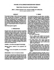
Figure 1 Floating-point execution unit capable of concurrent execution.
General designconsiderations
The programs considered “typical” by the user of highperformance computers are floating-point oriented. Therefore, the prime concern in designing the floating-point execution unit is to develop an overall organization which will match the performance of the instruction unit. However, the execution time of floating-point instructions is long compared with the issuing rate of these instructions by the instruction unit. The most obvious approach is to apply a faster technology and with special design techniques reduce the execution time for floating-point. But a study of many “typical” floating point programs revealed that the execution time per instruction would have to be 1 to 2 cycles in order to match the performance3of the instruction unit.* Conventional execution unit design, even with state-of-the-art algorithms, will not provide these execution times. Another approach considered was to provide execution concurrency among instructions; this obviously would require two complete floating-point execution units.+ An attendant requirement would be a floating-point instruction unit. This unit is necessary to sequence the operands from storage to the proper execution unit; it must buffer the instructions and assign each instruction to a non-busy execution unit. Also, since the execution time is not the same for all instructions the possibility now exists for ” _
* Even though the burst rate of the instruction unit is one instruction per cycle, it is not necessary to execute at the samerate. t Sincetwo complete executionunits m e necessaryforConcurrent execution,thecost-performancefactorisimportant.Analysis showed seven cycles for multithat execution times of three cycles for add and ply werereasonableexpectations.
out-of-sequence execution, andthe floating-point instruction must insure that executing out of sequence does not produce incorrect results.* The organization for an execution unit capable of concurrent execution is shown in Fig. 1. Buffering and sequence control of all instructions, storage operands, and floating-point accumulators are theresponsibility of the floating-point execution unit. Each of the execution units is capable of executing all floating-point instructions. One might be led to believe that this organization is a suitable solution in itself. If multiply can be executed insevencycles and two multiplies are executed simultaneously, then the effective execution time is 3.5 cycles. Similarly, for add the execution time would go from three cycles to 1.5 cycles. However, the operating delay of the floating-point instruction unit must be considered, and it is not always possible to execute concurrently because of the dependence among instructions. When these problems are considered the effective execution time is close to three cycles per instruction, which is not sufficient. A third execution unit would not help because the complexity of the floating-point instruction unit increases, and the amount of hardware becomes prohibitive. The next solution to be considered was to improve the execution time of each instruction by employing faster algorithms in the design of each execution unit. Obviously this would increase thehardware,but since the circuit * Dependenceamonginstructionsmust be controlled. If instruction n 1 isdependent on theresult of instruction n instruction n 1 mustnot be allowed to startuntilinstruction n is’completed.
+
+
MODEL
91
35
FLOATING-POINT EXECUTION
Table 1 Floating-point instructions executed by floating-point execution unit. Arithmetic Type
RR-RX RR
RX RR RR RR RR-RX RR-RX RR-RX RR-RX RR-RX RR RR-RX RR-RX
Condition Znstructionexceptions* Floating-point code
Load (S/L) Load and Test (S/L) Store (S/L) Load Complement (S/L) Load Positive (S/L) Load Negative (S/L) Add Normalized (S/L) Add Unnormalized (S/L) Subtract Normalized (S/L) Subtract Unnormalized (S/L) Compare (S/L) Halve (S/L) U, Multiply Divide U,
unit
NO
FLIU
YES NO YES YES YES YES YES ADD YES YES ADD YES
FLIU FLIU ADD ADD ADD ADD
NO NO NO
U, E, LS E, LS ADDU, E, LS E, LS
ADD E E, FK
M /D
M/D
Exceptions : U-Exponent-underflow exception E-Exponent-overflow exception LS-Significance exception FK-Floating Point Divide Exception
36
delay is a function not only of the circuit speedbut also of the number of loads on the input net and the length of the interconnection wiring, more hardware may not make the unit f a ~ t e r These .~ two factors-the desire for faster execution of each instruction and the size sensitivityof the circuit delay, have produced a concept which is unique to the organization of floating-point execution units, and which was adopted for the Model 91 : the concept of using separate execution units for different instruction types. Faster execution of each instruction canbeachieved if the conventional execution unit is separated into arithmetic units designed to execute a subset of the floating-point instructions instead of the entire set. This conclusion may not be obvious, but a unit designed exclusively for a class of similar instructions can executethose instructions faster than a unit designed to accommodate all floating-point instructions. The control sequences are shorter and less complex; the data flow path has fewer logic levels and rerequires lesshardware because the designer has more freedom incombining serial operations to eliminate circuit levels; the circuit delay per level is faster because lesshardwareis required in the smaller, autonomous units. To implement the concept in the Model 91, the floating-point instruction set was separated into two subsets: add and multiply/divide. Table 1 shows a list of the instructions and identifies the unit in which eachinstruction is executed. With this separation, an add unit which executed all add class instructions in two cycles, and a multiply/divide unit which executed multiply in six cycles and divide in eighteen cycles, were designed. The use of this concept somewhat changes the character
ANDERSON, EARLE, GOLDSCHMIDT AND POWERS
of concurrent execution. It is possible to have concurrent executionwith one execution unit-Le., two arithmetic units, add and multiply/divide. The performance is not quite as good as that attainable using two execution units, but less hardware is required for the implementation. Therefore, more arithmetic units can be added to improve the performance. First, two add units and two multiply/divide units were considered. But the floating-point instruction unit canassignonly one instruction percycle. Therefore, since an add operation is two cycles long, two add units could be replaced by one add unit if a new add class instruction could be started every cycle. This would introduce still another example of concurrent execution: concurrent execution within an arithmetic unit. Suchconcurrencywithin a unit is facilitated by the technique of pipelining. If a section of combinatorial logic, such as the logic to execute an add, could be designed with equal delay in all parallel paths through the logic, the rate at which new inputs could enter this section of logic would be independent of the total delay through the logic. However, delay is neverequal; skew is always presentand the interval between input signals mustbe greater than the total skew of the logic section. Buttemporary storage platforms can be inserted which will separate the section of combinatorial logic into smaller synchronous stages. Now the total skew has been dividedinto smaller pieces; only the skewbetweenstages has to be considered. The interval between inputs has decreased and now depends on the skewbetween temporary storage platforms.Essentially the temporary storage platform isused to separate one complete job, such as an add, into severalpieces;then
several jobs can be executed simultaneously. Thus, inputs can be applied at a predetermined rate and once the pipeline is full the outputs will match this rate. The technique of pipelining does have practical limits, and these limits differ for each application. In general the rate at which new inputs can be applied is limited by the logic preceding the pipeline (e.g., add is limited to one instruction per cycle by the floating-point instruction unit) or by the rate at which outputs can be accepted. Also, both the rate of new inputs and the length of the pipeline are limited by dependencies among stages of the pipeline or between theoutput and successive inputs (e.g., the output of one add can become an input for the next). The add unit requires two cycles for execution and is limited to one new input per cycle. Thus pipelining allows two instructions to be in execution concurrently, thereby increasing the efficiency with a small increase in hardware. Further study of pipelining techniques would indicate that a three-cycle multiply and a twelve-cycle divide are possible. Here the technique of pipelining is usedto speed up the iterative section of the multiply which is critical to multiply/divide execution. (This is discussed in detail in the section on the multiply/divide unit.) The execution unit would consist at this point of a floating-point instruction unit, an add unit which could startan instruction everycycle, and a multiply/divide unit whichwouldexecutemultiplyin three cycles and divide in twelvecycles.However the performance still would not match the instruction unit. The execution times would be adequate but the units would spend considerable time waiting for operands. Therefore, instead of duplicating the arithmetic unit (which is expensive) extra input bufferregisters have been added to collect the operands and necessary instruction control information. When both operands are available, the controlinformation is processed and a request made to use an arithmetic unit. These registers are referred to as "reservation stations." They can be and are treated as independent units. The final organization is shown in Fig. 2. It consists of three parts: thefloating-pointinstruction unit; thefloatingpoint add unit; and the floating-point multiply/divide unit. Another paper in this series3 explains the floating-point instruction unit in detail. The problems involved and both the considered solutions and the implemented solutions are discussed. The floating-point add unit has three reservation stations and, as stated above, is treated as three separate add units, Al, A2 and A3. The floating-point multiply/divide unit has two reservation stations, M/D1 and M/D2. The last two sections of this paper describe the design of these two units in detail. Floating-point terminology
The reader is assumed to be familiar withSystem/360 architecture and terminology.' However, the floating-point
TO ST( )RAGE VIA s1rORE DATA BIJFFERS
TO FX PT FR3M STORAGE
"1
INSTR UNIT
1 " "
_"""
t
FLOATING. POINT OP STACK (FLOS) FLOATING-
I
BUFFERS (FW
CONTROLS EXECUTION UNITS
CONTROLS
A[
i I
I
I I I I
I
I
ET%:
I I
I
I
RES STAT 1
A1
RES STAT 2 A2
RES STAT 1
RES STAT 3 A3
I
RES STAT 2
I
I
I I I I
MULTIPLY ITERATION
TWO-STAGE FLOATINGPOINT
I
I I I
" " "
PIPELINE
PROPAGATE
I
I
.
I
I I
6
RESULT
I
RESULT
I L
1
COMMON R
BUS
Figure 2 Overallorganization of floating-pointunit.
data format and terminology will be briefly reviewed here. Floating-point data occupy a fixed-length format, which may be either a full-word short format or a double-word format : Short Floating-point Binary Format
Sign Characteristic 0 1_
Fraction
_ _ _ _ 7 8 _ _ _ _ 31
Long Floating-point Binary Format
Sign Characteristic
Fraction
0 1 _ _ _ _ 7 8_
_ _ _ _ 63
The first bit(s) in either format is (are) the sign bit(s). The subsequent seven bit positions are occupied by the charac-
MODEL
91
37
FLOATING-POINT EXECUTION
FLR BUS
COMMON DATA BUS
CHARACTERISTIC (8 BITS)
FLB BUS
CHARACTERISTIC COMPARISON ANDPRE4HIFTING
\
FRACTION ADDER
/ FRACTION ADDER
POST. NORMALIZATION
IRESVLTI
7-
CHARACTERISTIC
+
COMMON RESULT BUS
Figure 3 Floating-point add data flow.
38
teristic. The fractionconsists ofsixhexadecimaldigits for the short format or 14 hexadecimal digits for the long. The radix point of the fraction is assumed to be immediately to the left of the high-order fraction digit. To provide the proper magnitude for the floating-point number, the fraction is considered to be multipliedby a power of 16. The characteristic portion, bits 1-7 of both floatingpoint formats, indicates this power. The characteristic is treated as an excess64 number with a range from -64 through "63 corresponding to the binary expression of the values 0-127. Both positive and negative quantities have a true fraction, the difference in signbeingindicated by the sign bit. The number is positive or negative accordinglyas the sign bit is zero or one.
ANDERSON, EARLE, GOLDSCHMIDT AND POWERS
A normalizedfloating-pointnumberhas a non-zero high-order hexadecimal fraction digit. To preserve maximumprecisioninsubsequent operation, addition, subtraction, multiplication, and division are performed with normalizedresults.(Addition and subtraction mayalso be programmed to be performed with unnormalized results. The operands for any floating-point operation can be either normalized or unnormalized.) Floating-point add unit
The challenge inthe design of the add unit was to minimize the number of logicallevels in the longestdelay path. However, the sequence of operations necessary for the execution of a floating-point add impedes the design goal.
Consider the following operations:
CA
> c,
c,-1111
(a) Since the radix point must be aligned before an add can proceed, the characteristics of the two operands must be compared andthe differencebetween them established. (b) This difference must be decodedinto the shift amount, and the fraction with the smaller characteristic shifted right a sufficient number of positions to make the characteristics equal. (c) Since subtraction is to be performed by forming the two's complement of one of the fractions and then adding the two fractions in the fraction adder, one of the fractions must pass through true/complement logic. (d)Thetwo operand fractions are added in a parallel adder. The carries must propagate from the low order end to the high order end. (e) Because of subtraction, the output must provide for both the true sum and the complement sum, depending on the high-order carry. (f) If the system architecture calls for left justification or normalized operation, the result out of the adder must be checkedfor high-order zeros and shifted left to remove these zeros. (g) The characteristic must be reduced by the amount of left shift necessary to normalize the resultant fraction. (h) The resultant operand must be stored in the proper accumulator. The above sequence of operations implies a series of sequential execution stages, each of which is dependent on the output of the previous stage. The problem then, is to arrange, change and mergethese operations to provide fast, efficient execution for a floating-point add. None of the steps can be eliminated. Each step is required in order to execute add; but the steps can be merged so that the interface between them iseliminated,* and each step can be changed to provide only the necessary information to the next stage, For example, the long data format consists of 14 hexadecimal digits; therefore any difference between the two characteristics which is greater than 14 will result in an all zero fraction. This means that the characteristic difference adder need not generate a sum for the high-order three bits. Instead, if the difference is greater than 14, a shift of 15 is forced. As a result, the characteristic difference adder is faster and less expensive. The add unit algorithm is separated into three parts: characteristic comparison and pre-shifting, fraction adder, and post-normalization (Fig. 3). The first section, the characteristic comparison and pre-shifting operation, merges the first three operations from the sequence given above; the second section-the fraction adder-merges the next two operations; the final section-post normaliza-
___-
*Levelsare used toencodetheoutput of one step,whichis subsequently decoded in the next step. Merging the two steps will eliminate these levels.
C,=l
1 0 0
1 1 1 1 1 0 0 0 0 1 0 1 1 1
1 (RESULT IS TRUE) 1 1 1 0 1 1 1 1
(RESULT IS COMPLEMENT) 0
1 1 1 0 1 10 0
COMP.RESULT
0 0 10 0 1 1
1 0
1 00 0
c, -
c, HOT ONE
C, C,-
HOT ONE
1
MUST ADD HOT ONE
0 0 1 0 1 0 0 c,-c, - - - -- - - - - - - - - - - - - - - - - - - - - - - - - - - - - - - - - - - - C,
c
C, (END-AROUND CARRY) 1 1 0 1 0 0 0 0
0 0 0 0 0 1 1 1 10 10 1 1
COMPLEMENT
0 0 10 10 0
(NO CARRY)
c, c, CORRECT RESULT
-"-
"""~"~"""""~""~""~"~""
Figure 4 Examples of exponent arithmetic.
tion-merges the final three operations. The hardware implementation of each of these three sections is discussed below. Implementation Characteristic comparison and pre-shifting
The first stage of execution for all two-operand instructions (floating-point add, subtract, and compare) is to compare the characteristics and establish the magnitude of the difference between them. The characteristic (C,) of one operand is always subtracted from the characteristic (C,) of the other operand (CA - C,). Characteristic B is always complemented as it is gated in at the reservation station. If the output of the characteristic difference adder is thetrue sum or the complement of the true sum, the output can be decoded directly at the pre-shifter. But the adder always subtracts CB from CA and if CB > C, the sum would be negative. Therefore, to eliminate the possibility of having to add a 1 in the low order position and complementwhen C, is greater than CA, an "endaround-carry'' adder is used. This is shown by the example in Fig. 4. The characteristic comparison can result in two statesCA CB or CB > CA.If CA C,, there is a carry out of the high order position of the characteristic difference adder, and the carry is used to gate the fraction of operand B to the pre-shifter. The true sum output of the characteristic difference adder is the amountthatthe fraction must be shifted right to make the characteristics
>
>
MODEL
91
39
FLOATING-POINT EXECUTION
INPUTS DIGITS
0
0
0
1
1 2
1
0 1
0 1
2
2
2
3
3
3
4
4
5
FIRST LEVEL
1 2
2
3
3
4
4 5
5 6
6 SHF RIGHT 0 SHF RIGHT 1 SHF RIGHT 2 SHF RIGHT 3
SECOND LEVEL
SHF RIGHT 0 SHF RIGHT 4
" "
"------" -
0
" "
SHF RIGHT 8 " SHF RIGHT12
2
3
2
3
4 5
4
6
6
7
7 8 9
9
10
10
8 11
5 7 8 9
10 11
12
Figure 5 Digitpre-shifter.
40
equal. If C, > CA,there is no carry out of the high order position of the characteristicdifference adder, and the absence of a carry is used to gate the fraction of operand A to the pre-shifter. In this case the complement of the sum output of the characteristic difference adder is the amount that the fraction must be shifted rightto make the characteristicsequal. In bothcases the second operand fraction (the one with the larger characteristic) isgated to the true-complement input of the fraction adder. The characteristic of the unshifted fraction becomes the resultant characteristic. It is gated to the characteristicupdate adder, and after updating, if necessary, it is gated to the accumulator specified bythe instruction. The output of the characteristicdifference adder is decoded by the pre-shifter and the proper fraction shifted right the necessary number of positions. The pre-shifter is a parallel digit-shifter which shifts each of the 14 digits right any amount from zero to fifteen. The decode of the shift amount is designedinto each level, thereby eliminating serial logic levels for decoding. The pre-shifter consists of two circuit levels. The first level shifts a digit right by 0, 1, 2 or 3 digit positions. The secondlevelshifts a digit right by 0, 4, 8, or 12 digit positions. Thus, by the proper combination of these amounts any right digit shift between and including 0 and 15 canbeexecuted. Figure 5 shows an example of the pre-shifter. The un-shifted fraction is gated to the true/complement gates of the adder. Here the fractionisgatedunchanged
ANDERSON, EARLE, GOLDSCHMIDT AND POWERS
if the effective operation is ADD and complemented if the effective operation is SUBTRACT. The true/complement gating is overlapped with the pre-shifter on a time basis. The output of both the true/complement logic and the pre-shifter are the inputs to the fraction adder.
Fraction adder Most of the time required for binary adders is carry propagation time. Two operands must be combined and the carriesallowed to ripple from right (low order) to left (high order). The usual method of finding the sum is to combine the half sum* of bit n (higher order) with the The carry carry from bit n - 1 (S, = A , Q Bn v en).+ (C,) into bit position n is also a three term expression which includes the carry into bit position n - 1
If the carry term is rearrangedto read
twonew terms can be defined which separate the carry into twoparts-generated carry, and propagated carry. The generated carry (Gn-l) is defined as A n - 1 Bn-l, . and the carry propagate function (often abbreviated to simply propagate or PnJ isdefined as An-1 V Bn-l. Now the * The half sum is the exclusive OR of the two input bits, (A, V B"). iThe two operand fractionsaredesignatedas A , B andthe bits as An, Bn, An-1, Bn-I, etc. GIi s thecarryinto bit position n, which is the carry out from bit n 1.
-
carry expression can be rewrittenas:’”
e, =
G,-1
v Pn-lCn-l
C,, =
G,-1
V
Pn-lGn-1
V Pn-lPn-zCn-z
C,,= G,-l V Pn-lGn-lV Pn--lPn-zGz-z
v
’
Pn-1Pn4Pn-3Cn-3
The expansion can continue as far as one desires and one couldconceive of C, beinggenerated by onelarge OR blockpreceded by several AND blocks(in fact n AND blocks-one for eachstage).But it is obvious that the limiting factor would be the circuit fan-in. Only a limited number of circuitstagescanbeconnectedtogetherin this manner.This technique is defined as carry look-ahead, and by cascading different levels of look-ahead the technique can be made to fit the circuit fan-in, fan-out limitations. For example, assume that four bits can be arranged in this manner, and that each four bits form a “group.” The adder isnowdivided into groups and the carries and propagates can be arranged for carry look-ahead between groups just as they were for look-ahead between bits. It is possible to carry the concept even further and define a section as consisting of one or moregroups.Now the adder has three levelsof carry look-ahead: the bit level of look-ahead, the group level, and the section level. The fraction adder of the floating-point add unit is a carry look-ahead adder. A group is made up of four bits (onedigit) and twogroupsform a section.Since it must be capable of adding 56 bits, the fraction adder consists of seven sections and 14 groups. Each pair of input bits generate the three bitfunctions:half-sum ( A v B), bit carry generate ( A . B) and bit propagate ( A V B). These functions are combined to form the group generate and propagate which in turn are combined to form the section generate and propagate. A typical group is shownin Fig. 6 and the group and section look-ahead are shown in Fig. 7. The high-order sum consists of nine bits to include the end-around carry for subtraction and the overflow bit for addition. The end-around carry is needed for subtraction because the fraction which is complemented may not be the subtrahend. This is illustrated by the example given in the description of the characteristic comparison. If the effective sign of the instruction is minus (the exclusive OR of the sign of the two fractions and the instruction is the effectivesign) the effective operation is subtract. Also, the high-order bit (ninth bit of the high order section) is set to a one, thus conditioning it for an end-around-carry. If there is no end-around-carry when the effectivesign is minus the adder output is complemented.
Post-normalization Normalization or post-shifting takes place when the intermediate arithmetic result out of the adder is changed to the final result.The output of the fraction adder is checked for high-order zero digits and the fraction is left-shifted until the high-order digit is non-zero. The output of the fraction adder is gated to the zerodigitchecker. The zero-digitcheckerissimply a large decoder, which detects the number of leading zero digits, and provides the shift amount to the post-shifter. Since this same amount must be subtracted from the characteristic, the zero-digitchecker also mustencode the shift amount for the characteristic update adder. The implementation of the digit post-shifter isthe same as the digit pre-shifter except for the fact that the postshift is a left-shift. The first level of the post-shifter shifts each of the 14 digits left 0, 1, 2 or 3 and the second level shifts each digit 0, 4, 8, or 12. The output of the second level is gatedinto the add unit fraction result register, from which the resultant fraction isrouted to the proper floatingpoint accumulator. The characteristic update isexecuted in parallel with the fractionshift. The zero-digitcheckerprovides the characteristic update adder with the two’s complement of the amount by which the characteristic must be reduced. Since it is not possible to have a post-shift greater than 13, the high-order three bits of the characteristic can only be changed by carries which ripple from the low order four bits. The update adder makes use of this fact to reduce the necessary hardware and speed up the operation. Floating-point multiply/divide unit
Multiply and divide are complicated operations. However, two of the original design goals were to select an algorithm for each operation such that (1) both operations couldusecommon hardware, and (2) improvement in execution time could be achieved which would be comparable to that achieved in the floating-point add unit. Several algorithms exist for each instruction which make the first design goal attainable. Unfortunately, the best of the algorithms generally used for divide are not capable of providing an improvement in execution comparable to the improvementachievable by those used for multiply. The algorithm developed for divide in the Model 91 uses multiplication as the basic operator. Thus, common hardware is used, and comparable improvement in the execution time is achieved. In order to give a clear, consistent treatment to both instructions, this section discusses the multiply algorithm and hardware implementation first. Then the divide algoit is shownhow rithm isdiscussedseparately.Finally, divideutilizes the multiplyexecution hardware and the hardware whichis unique to the execution of divide is described.
MODEL
41
91 FLOATING-POINT EXECUTION
GATE HALF SUM 7
BIT A7 BIT 87 -
TRUE AND COMPLEMENT BIT SUM GENERATION
GROUP
BIT HALF SUM BIT PROPAGATES BIT GENERATES
' qTk ' gyk
PROPAGATE
GROUP
2
TRUESUM
SUM LATCH
LOW ORDER
PROPAGATE GENERATE
COMPSUM
GROUPPROPAGATE GROUP 1
~~
GATE COMP GATE TRUE TRUESUM BIT A6BIT 8 6
-
HALF SUM PROPAGATE
-P6
GENERATE
__ G6 GATE COMP ___(
COMPSUM
P1 PO
1
HALF SUM PROPAGATE
BIT E5-
GENERATE
qTk
PGL
GROUPGENERATE GROUP 2
G7P6P5P4 G6P5P4 BIT A5-
PG2
P5 P4
~
G4
-P5 -G5
G5P4
GG2
GROUPGENERATE GROUP 1 T HALF SUM PROPAGATE -P4 GENERATE -G4
BIT A4BIT 84-
-
G3P2PIPO GPPlPO G I P O a T F G G 1
TRUESUM
GO
~
G7P6P5+G6P5
+
G5+CFlP7P6P5 CT
~HALF SUM PROPAGATE 3" GENERATE -G3
BIT A3BIT 83-
e
COMPSUM
-
TRUESUM
-&SUM BIT 3
PGPCFI+GG2 C-
-
COMPSUM
NOTE. 4 BITS = 1 GROUP 8 BITS = 1 SECTION GG AND PG AREGROUPGENERATE AND GROUPPROPAGATE GS AN0 PSARE SECTION GENERATE AN0 SECTION PROPAGATE P AND G ARE BIT GENERATE ANDBIT PROPAGATE
-
TRUESUM BIT A2BIT 82-
HALF SUM PROPAGATE -P2 GENERATE " G 2
GG2P3+G3 CFlPG2P3
-
7
BIT A1 BIT B1
- HALF SUM - PROPAGATE GENERATE
COMPSUM
TRUESUM
-
COMPSUM
-
~
-PI " G 1
GGZP3PP+G3P2
+
GZ+CFlPGZP3P2
BIT AOBIT BO-
BITS A SOURCE IS PRE-SHIFTER BITS B SOURCE IS T/C GATES CF1, GATE TRUE, AND GATECOMP SOURCE IS CARRY LOOK-AHEAD
-
TRUESUM
HIGH ORDER
HALF SUM
PROPAGATE -PO GENERATE -GO
GG2P3P2P1 -k
G3PZPl+G2P1
t Gl+CFIP3P2Pl C
-
COMPSUM
Figure 6 Fraction adder, section 1 (high-order).
Multiply algorithm plementing to allow subtraction as well as addition can Computers usuallyexecute multiply by repetitive ad&be used to reduce the nUlnber of necessary additions* Aninteger in any number systemmaybe written in tion, and the time required is dependent on the number of additions required.'.' A zero bit in the multiplier results in the form: adding a zero word to thepartial product. Therefore, because shifting is a faster operation thanadd,the execuanbn f an-lbn-l f ' f tion time can be decreased by shifting over a zero or a string of zeros. Any improvement in the multiply executionwhere beyond this point is not obvious. However, certain properties of the binary number system combined withcorn0 a b - 1, and b = base of the number system
+
42
ANDERSON., EARLE, GOLDSCHMIDTAND
<