The Induction Plasma Chemical Reactor: Part I. Equilibrium Model. G. Y. Zhao, ~ J. Mostaghimi, 2 and M. I. Boulos 2. Received September 2, 1988, revised July ...
Plasma Chemistry and Plasma Processing, Vol. 10, No. l, 1990
T h e Induction P l a s m a C h e m i c a l Reactor: Part I. Equilibrium M o d e l G. Y. Zhao, ~ J. Mostaghimi, 2 and M. I. Boulos 2 Received September 2, 1988, revised July 17, 1989
A mathematical model is presented .[or the numerical simulation of the flow, temperature, and concentration fields in an rf plasma chemical reactor. The simulation is perJormed assuming chemical equilibrium. The extent of validity of this assumption is discussed. The system considered is the reaction of SiCl4 and NH~ .lbr tbe production of Si.~N4.
KEY WORDS: Induction plasma; modeling; chemical equilibrium; silicon nitride synthesis. 1. I N T R O D U C T I O N RF induction plasma reactors offer a high enthalpy and pure medium free of electrode contamination for plasma chemistry. Due to these features, they have found a number of applications involving chemical synthesis. A better understanding of the chemical processes involved includes full modeling of the transport processes in these reactors. The modeling of fluid flow, temperature, and concentration fields in rf plasmas has greatly advanced in recent years. However, the models have been restricted to cases where no chemical synthesis occurred in the torch. The present paper represents one step toward the full modeling of fundamental processes involved in the use of the induction plasma as a chemical reactor. The assumptions involved are essentially similar to those used in previous works, ~~,2~aiming at the calculation of the flow, temperature, and concentration fields in an inductively coupled rf plasma. These are: --steady-state, laminar flow with negligible viscous dissipation, i Institute of Mechanics, Chinese Academyof Sciences, Beijing, People's Republic of China. Department of Chemical Engineering, Universit~ de Sherbrooke. Sherbrooke, Quebec, Canada, JIK 2R1. 133 0272-4324'90~0300-0133506.00/0 t 1900 Plenum Publishin~ Corporation
134
Zhao, Mostaghimi, and Boulos
- - l o c a l thermodynamic equilibrium, --optically thin plasma, --two-dimensional, rotationally symmetric flow, and temperature and concentration fields with one-dimensional electromagnetic fields. In addition, three other assumptions were necessary in this work, these are: - - T h e Lewis number is equal to unity for all species. - - T h e diffusion coefficients for all species are equal and are calculated from the mixture thermal conductivity data by setting the Lewis number of the mixture equal to unity. - - T h e plasma is in chemical equilibrium. The third assumption is particularly important since it implies that the reacting system involved has chemical reaction kinetics that are considerably faster than the associated heat and mass transfer processes. While this assumption might not be true for many reacting systems, the principal contribution of this work lies in the development of the proposed approach as a first approximation to the considerably more complex case of chemical reactor modeling. The latter case is fully dealt with in the second part of this paper where a comparison is made between the predictions of the equilibrium model and that of a model taking into account the kinetic rates of all of the chemical reactions involved. It should be underlined that the chemical equilibrium model offers a relatively simple means of studying the mixing in a plasma reactor. The numerical simulation of rf plasma reactors has so far received little attention. Harada e t al. °~ performed a simple numerical simulation of the flow inside a reactor. Yoshida et al. ~4~ calculated the thermodynamic equilibrium compositions for a Si3N4 plasma reactor. Zhao and Zhu ~~ also considered the flow in a Si3N4 plasma chemical reactor under typical operating conditions. This calculation, however, did not consider the chemical reactions. Oxidation of titanium chloride in a turbulent chemical reactor was considered by Zhao et a l . ' . The plasma torch was not, however, included in this model. In this study a mathematical model is presented for the numerical simulation of the flow, temperature, and species concentrations fields in a radio-frequency plasma chemical reactor for the synthesis of Si3N4 ultrafine powder with argon as the plasma gas and SiCI4 and NH3 as reactants. The model is based on the rotationally symmetric continuity, momentum, energy, and species conservation equations along with the one-dimensional electromagnetic field equations. Particular attention is given to the determination of the species concentrations. Assuming chemical equilibrium, the species concentration is determined by minimizing the Gibbs free energy. The model
Induction Plasma Chemical Reactor, I
135
is applied to an rf plasma reactor with a small water-cooled stainless steel tube inserted into it. A study of the effects of the operating conditions on the flow, temperature, and species concentration fields is carried out. 2. G O V E R N I N G E Q U A T I O N S
Lo!
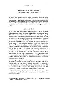
A schematic of the torch geometry is shown in Fig. 1. The governing equations used in the model are the continuity, momentum, energy, and
Q3 Q2Qt
0
0
P --Io[kw] f -- 3[MHz] QI = I[LPM] SiCI 4
i 0
Qz = IO[/PM] Ar
0
Q3 = 6 0 [ L P M ] A r
Q, -IO[LPM] NH~ "-Q4 r~ : 25 [m/s] Lo -- z,o[cm] L c = 5.0 [ cm] L I = 8.8[ cm] L2 : II.0 [crn] L3
L~ : 9 9 [cm] ~,,: 0.2 [~m] DH : 0.2 [crn]
R,i = O.17[cm] R,Z: 0 . 3 7 [ c m ]
R2 : 1.5 [cr.] Re : 1.75 [cm] Rc : 2 . 9 [ c m ]
Fig. 1. Schematic of the torch geometry and the system of coordinates.
136
Zhao, Mostaghimi, and Boulos
species conservation (diffusion) equations along with the one-dimensional electromagnetic field equations. They are as follows:
Continuity: 0
0
a~ (rpu) +~r (rpv) = 0
(1)
Momentum :
)
u Ou+ au = ! a r
°,, Tz
V~r
av 0=
0rLr
r
U--nt-
]
/ou a~\ 2~ trr+rz) +rz 1 o
2r/X~r
+--
~
~_----
~-r/
r Or
az
P u az
Or
r~ = - r- -Or r-tx ~r
,,~ +
-
+ pg
_OP+F~
Uz/
(3)
ar
~rkr/
az\
(2)
Or~
(4)
where u, v, and w are the velocity components in the z, r, and 0 directions, respectively, p is pressure, p and p. are density and viscosity, pg is the gravity force, and Fr is the Lorentz electromagnetic force (see Eq. (17)] acting on the plasma gas in the discharge region.
Energy: p
( u -OH vOH~= -1[a (r~OH)+O (r~OH)] + P - O r -+ az
-~r:
r ~z
~z
Or
~r
(5)
where H is the total enthalpy, k the thermal conductivity, cp the specific heat of the mixture at constant pressure, P the volumetric rate of heat generation due to Joule heating, and Qr the radiative power loss per unit volume.
Diffusion : P( u OCi+ v --~-r OC~/
+w,, i=1,2,...,
N,,
(6)
where C,, pDi, IV,, and NL. are the mass fraction, the diffusion coefficient, the mass rate of formation/destruction of species i, and the number of species, respectively. The assumption of equality of diffusion coefficients for all species, along with the chemical equilibrium assumption, enables us to considerably simplify the calculation of the concentration fields. Under these assumptions, it is more convenient to utilize the element mass fraction
Induction Plasma Chemical Reactor,
I
137
K,, rather than the species mass fraction Ci, since K i is a conserved quantity. The quantity kj is related to the species mass fraction Ci by Ne
Kj = ~ aj,C;,
j = 1, 2,..., M
(7)
i=1
where the coefficient aj, is the mass of the jth element in one unit mass of the ith species, while M is the number of the elements. Since pDi = pD, we can multiply Eq. (6) by aj~ and sum it over i = 1 ~ Ne; the result is
'-~-r/=r p ( u OK'+vOKj~
OKj\+O(Or rpD O~Kr')1 rpD-~-z)
(8)
Such a formulation eliminates the chemical source term if',. The calculation procedure is as follows. The element concentration field equations for Ar, Si, H, N, and CI are solved along with the continuity, momentum, energy, and electromagnetic field equations. Once the element concentrations and the enthalpy have been obtained, the species concentrations are calculated. The equilibrium compositions are obtained using a penalty method for minimizing the Gibbs free energy G, ~'I
NI,
N
G= E O'j'n,+ E E n~,[O',j+RTln{fo/f'~'A] j=l
./=t
(9)
i=t
under the following conditions:
i. Chemical equilibrium" AI
Nv
N
v Aonj+~ ~ Ai,nij=b~ ' j=t
.i=t
I=I,2,...,N,.
(10)
i=1
ii. Phase equilibrium: N t,
n!i=n,,,
i = 1 , 2 . . . . . N,.
(11)
.i = I
ii. Nonnegativity constraints: n0->0 ,
i = 1 , 2 . . . . ,N,.,
nj>-O,
j = 1 , 2 , . . . , M,.
j=I,2,...,N v
(12)
where M, represents the number of components present as condensed phases, Np the number of phases, N,. the number of components in mixed phases, nii the number of moles of component i in phase j, nj the total number of moles in phase j, G~' and G~i~ithe partial Gibbs energy at the reference state, R the gas constant, T the absolute temperature, .~, the partial fugacity of species i in phase j, f o the fugacity of species i in phase
138
Zhao, Mostaghimi, and Boulos
I
1
I
I
I
Ar NH4Cl
iO
HCl
-I
N2
CI
10 - I
Z 0
10 - 2
,,0-2
Cl4
u_
(13
10 - 3
10 - 3
10 - 4
10 - 4 o
lOOO
2000
aooo
4000
5000
6000
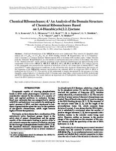
TEMPERATURE [ K] Fig. 2. Equilibrium composition as function of temperature for the Ar-Si-H-CI-N system at atmospheric pressure for an Ar: SiCh : NH~ molar ratio of 0.67 : 0.03 : 0.30. j at the reference state, A , the n u m b e r of element I in the c o m p o n e n t i, b~ the total n u m b e r of moles o f element I, and n, the total n u m b e r o f moles o f c o m p o n e n t i distributed a m o n g all phases. The species considered in this work are At, SIC14, NH~, Si3N4 (solid), H2, CI, SiCI, H, N2, SiCI3, Si (gas), SiCI2, SiHSi (liquid), NH4CI (solid), and HCI. Figure 2 shows the results of a sample calculation for a mixture of Ar, SiCI4 and NH3 under atmospheric pressure. The Gibbs free energy is obtained from Ref. 7. Due to the lack of data for temperatures higher than 6000 K, the species concentration profiles are calculated up to this temperature. Fortunately, the high-temperature region, i.e., T > 6000 K, is basically confined to the discharge region in the torch where the gas is almost pure argon. 2.1. Electromagnetic Field Equations
In some recent works '~'~ it is shown that the flow and temperature fields c o m p u t e d using the 1D electromagnetic field model were not substantially different from those obtained using the 2D electromagnetic field model for the present operating conditions and the torch geometry. The 1D E and H field representation was therefore used in this study with the corresponding equations given as f o l l o w s ~ : dEo -- dr
E. r
/.totoH: sin X
(13)
Induction Plasma Chemical Reactor, I
139
dH. " = - o ' E o cos X dr dx --= dr
¢rEo . tzowl'fsin X - - - c o s 1t: Eo
(14)
X
(15)
w h e r e Eo, H=, a n d X are the c i r c u m f e r e n t i a l electric intensity, the axial m a g n e t i c field intensity, a n d the p h a s e difference b e t w e e n the two fields, respectively, P-o the m a g n e t i c p e r m e a b i l i t y o f v a c u u m , a n d w the o s c i l l a t o r a n g u l a r f r e q u e n c y (2rrf). The quantities Fr a n d P in Eqs. (3) a n d (5) can be written as
3. B O U N D A R Y
P=crE~
(16)
Fr = ~tzoEoH: cos X
(17)
CONDITIONS
The b o u n d a r y c o n d i t i o n s for Eqs. ( 1 ) - ( 5 ) , (8), a n d (13)-(15) are as follows: i. Inlet conditions (z = 0): 0< r< Ril
u = Qt/rrR-ll t;=w=O (18)
Csicl~ = 1 T = 350 K R,2 < r < R2
u = Q2/ rr( R~ - R~2)
v=O w = 25 m / s
(19)
CA,-= 1 T = 350 K R2