MATEC Web of Conferences 112, 03009 (2017)
DOI: 10.1051/ matecconf/201711203009
IManE&E 2017
The influence of build orientation on the mechanical properties of medical implants made from PA 2200 by Selective Laser Sintering Răzvan Păcurar*, Ancuţa Păcurar, and Anna Petrilak Technical University of Cluj-Napoca, Faculty of Machine Building, Department of Manufacturing Engineering, B-dul Muncii no. 103-105, 400641, Cluj-Napoca, Romania
Abstract. This paper presents a series of research that have been made by the authors in the field of medical implants realized from PA 2200 powder material using the Selective Laser Sintering (SLS) method. Several sets of samples differently oriented into the working area of the machine were manufactured from PA 2200 by SLS, in order to determine which is the recommended orientation to be used during the manufacturing process, in such a way that at the end the mechanical properties (e.g. Compressive strength, Young’s modulus, etc.) will be as closed as possible to the ones of the human bones. The obtained results were further on used in the case of a medical implant (Acetabular liner) that was manufactured at the Technical University of Cluj-Napoca (TUCN) from PA 2200 material using the DTM Sinterstation 2000 SLS equipment.
1 Introduction Additive manufacturing (AM) technologies are widely used in medical field to produce human bone replacements and different types of prostheses, dental or hip joint replacement, etc [1,2]. Selective Laser Sintering (SLS) technology is one of the most developed AM technologies which nowadays are widely used for producing medical implants directly from biomaterials (PA 2200, PEEK, etc) [3,4]. A significant condition to produce medical implants by Selective Laser Sintering technology is to use a biocompatible material with the closest mechanical and material properties to those of the bone structure which must be replaced by surgical intervention [5,6]. Biocompatibility is related to the behavior of the biomaterials . The biocompatibility of scaffolds has to be similar with the one of the human bone, from the mechanical, chemical and biological point of view [7]. Also the biocompatible material must have the possibility to perform as a substrate that will support the appropriate cellular activity and also to optimize tissue generation [8, 9]. Other important characteristics are the biomechanical properties of the total hip replacement produced by SLS technology which should be the closest to the human bone properties. The mechanical properties of the hip joint prostheses produced by SLS depend on the process parameters and the part orientation used during the manufacturing process. In the last years, *
Corresponding author:
[email protected]
© The Authors, published by EDP Sciences. This is an open access article distributed under the terms of the Creative Commons Attribution License 4.0 (http://creativecommons.org/licenses/by/4.0/).
MATEC Web of Conferences 112, 03009 (2017)
DOI: 10.1051/ matecconf/201711203009
IManE&E 2017
a significant research effort has been focused on the optimization of the SLS process parameters (laser power, scanning speed, layer thickness, etc.) for each type of material tested for producing different types of customized medical implants by using this technology [10,11]. In order to determine the influence of the process parameters on the mechanical properties of the SLS parts, researchers have tried to use different approaches to obtain better results regarding the process [12]. Many researchers have varied the laser power or scanning speed and maintained constant the other parameters to determine their influence on the mechanical properties of the manufactured parts [13,14]. Another approach was to determine the influence of different position and part building orientations on the mechanical characteristics of different types of customized medical implants made from biocompatible materials by SLS [15,16]. This paper presents results that were obtained at the Technical University of Cluj-Napoca (TUC-N) in the case of testing the influence of build orientations of samples made from PA2200 powder by SLS, on the mechanical properties of these samples (compressive strength, Young’s modulus, etc.)
2 SLS manufacturing setup In order to determine the mechanical properties of the PA 2200 powder under compressive loads, 50 compressive test samples were designed using Solidworks CAD program. According to the Standard Test Method for Compressive Properties of Rigid Plastics - ISO 604, the 50 samples have been realized with the same rectangular shape and dimensions: 12.7 x 12.7 x 25.4 mm. In order to easily identify the parts after the manufacturing process, the samples have been numbered from 1 to 50. In the current research four different types of orientations of the samples have been used: first batch of 10 samples placed in the building chamber were oriented at 0° along the Y-axis, the second batch of 10 samples were oriented at 90° (perpendicular to the Y- axis). In order to avoid collisions between the first two batches, the second one was translated along the z-axis with 19 mm from the building platform. The third batch orientation was similar to the first one (oriented at 0° along the Y-axis) , but having a 36 mm translation along the Z-axis in this case, while the fourth batch orientation was similar to the second one (at 90° - perpendicular to the Y- axis) but having a 51 mm translation along the Z-axis in this case. The last batch of 10 samples was split in two categories: the first five samples being oriented at -45° with respects to the Z-axis, the other five ones being oriented at +45° with respects to the Z-axis. The last batch was translated with a value of 70 mm along the Z-axis. The mechanical properties of the parts produced by Selective Laser Sintering depend not only on the part orientation, but also on the process parameters (laser power [W]; scanning speed [mm/s] and layer thickness [mm]). In the case of the made research, only the laser power [W] was modified during the manufacturing process of the samples. The first, second and fifth batch of 10 samples were manufactured by using P=4,5 [W] laser power, the third and the fourth set of samples being realized with a laser power of P=4 [W]. The layer thickness of 0.1 [mm] and the scanning speed S=1257.3 [mm/s] were maintained constant in all cases. All samples were scaled before being manufactured by SLS with the following factors: 1.03510 (along X-axis); 1.03310 (along Y-axis) and 1.01800 (along Zaxis).
3 Samples manufactured by SLS and compressive tests The selective laser sintering (SLS) process requires three stages to be strictly followed during the manufacturing process, while temperature values are varied in the building chamber: warm up stage, when the temperature gradually increases from 60°C to the
2
MATEC Web of Conferences 112, 03009 (2017)
DOI: 10.1051/ matecconf/201711203009
IManE&E 2017
melting point of the material, which in this case was setup to 170°C; the build stage, when the temperature is maintained fixed at 170 °C during the entire manufacturing process and the cool down stage, when the temperature gradually decreases from 170°C to 95°C in order to avoid deformations and shrinkage of the manufactured parts.
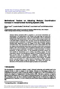
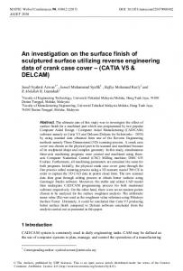
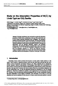
Fig.1. DTM Sinterstation 2000 equipment, samples and compressive tests performed using the ZD 40 Tension-Compressive Testing Machine from TUC-N.
In order to determine which is the correlation between the laser power and part orientation with the mechanical properties of the samples manufactured from PA2200 powder using the DTM Sinterstation 2000 equipment from TUC-N presented in Fig. 1, and under compressive loads of the biocompatible PA 2200 samples, compressive mechanical test were performed using the ZD 40 Tension-Compressive Testing Machine from TUC-N which is also presented in the last image of Fig.1. The compressive strain was calculated for each sample tested with the following equation: ε = dl/l0
(1)
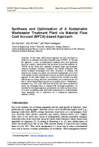
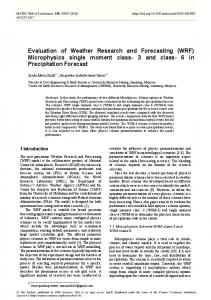
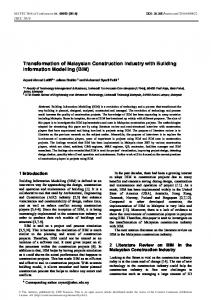
where: dl-change of length [mm], l0‐ initial dimension (25.4 mm) and ε -engineering strain. The curves of the PA2200 samples determined by compressive tests are shown for each batch in Fig. 2. The compressive stress was calculated with the following equation: σ = Fn/A
(2)
where: σ- compressive stress [N/mm2], Fn-normal compressive force [N] and A is the crosssectional area of the samples (12.7x12.7=161.29 mm2) As shown in Figure 2, the curves show a state of deformation in the range 0 - 0.1 mm in which the stress is zero corresponds to the self-positioning of the samples in the grips of the testing machine. As one may notice in Fig. 2, the results obtained in the case of samples 610, 16-20, 26-30 and 36-40 were not presented, because the obtained values were very similar to the ones shown in the diagrams and the intention was to reduce the volume of the output data. This is the main reason why, in the case of each batch, only the most 5 representative values were displayed in the diagrams. As regarding the obtained data, according to Fig. 2, the highest values of the mechanical strength (before failure) were obtained in the case of the first batch of samples, which was manufactured with a P=4.5W laser power and with an orientation of 0° along the Y-axis (Fig. 2, a). The highest value of the compressive stress has been determined in the case of Sample no 2 (Rm= 128.87 N/mm2). The lowest value of the mechanical strength was obtained in the case of the fourth batch of samples which were manufactured with a P=4 W laser power and with an orientation of 90° along the y-axis. The value obtained in the case of sample no. 34 was approximately six times lower as compared to the most resistant sample (Rm= 21.78 N/mm2). Values in the range 125-160 [N/mm2] according to 3
MATEC Web of Conferences 112, 03009 (2017)
DOI: 10.1051/ matecconf/201711203009
IManE&E 2017
the age of the patient are reference values for the compressive strength of the human bones [17]. It can be concluded that for manufacturing parts from PA2200 powder by selective laser sintering technology it is more suitable to use a laser power P=4.5 [W] combined with a build orientation of 0° along Y-axis in the case of parts made by SLS, so as a higher mechanical strength will be obtained at the end.
a) Compressive curves samples 1-5 (Ө =0°)
b) Compressive curves samples 11-15 (Ө =90°)
c) Compressive curves samples 21-25 (Ө =0°)
d) Compressive curves samples 31-35 (Ө =90°)
e) Compressive curves samples 41-45 (Ө =-45°) f) Compressive curves samples 46-50 (Ө =+45°) Fig.2. Stress-strain compressive curves of PA 2200 samples made by SLS.
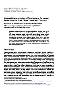
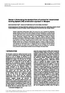
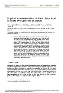
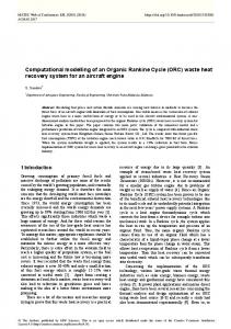
The Young’s modulus determined by the compressive tests for each batch of PA2200 samples manufactured by SLS, are shown in Fig. 3. These values were calculated from the tangent at the beginning of the curvilinear region of the stress-strain curve using the Test
4
MATEC Web of Conferences 112, 03009 (2017)
DOI: 10.1051/ matecconf/201711203009
IManE&E 2017
and Motion software of the ZD 40 Tension-Compressive Testing Machine. As noticeable in Fig. 3, the lowest value of Young’s modulus was obtained in the case of the last batch of five samples manufactured from PA2200 by Selective Laser Sintering (SLS) technology (manufactured with an orientation +45° with respects to the Z-axis), while the highest values were obtained in the case of the first batch manufactured by SLS with an orientation of 0° along the Y-axis. It can be concluded that the first batch presents a more pronounced elastic behavior than plastic behavior during the axial loading. The lowest value (32.42 GPa – see Fig.3, e) obtained in the case when the sample was manufactured at +45° with respects to the Z-axis was the closest one to the value of Young’s modulus reported in the case of the human bone (18-21 GPa) [18].
a) Young’s Modulus for samples 1-5
b) Young’s Modulus for samples 11-15
c) Young’s Modulus for samples 21-25
d) Young’s Modulus for samples 31-35
e) Young’s Modulus for samples 41-45
f) Young’s Modulus for samples 46-50
Fig.3. Young’s modulus of the PA 2200 samples determined by compressive tests.
5
MATEC Web of Conferences 112, 03009 (2017)
DOI: 10.1051/ matecconf/201711203009
IManE&E 2017
4 Conclusions A total batch of 50 compressive test samples was manufactured from PA2200 biocompatible material by selective laser sintering (SLS) technology using a DTM Sinterstation 2000 SLS equipment from the Technical University of Cluj-Napoca (TUC-N), with the aim of performing compressive tests according to ISO 604 standard using a Universal Testing Machine which is available also at TUC-N. The manufacturing process of the samples was realized with different laser power values (4-4.5 W) and different build orientations in the working area of the machine. The compressive tests that were realized further on emphasized that a laser power having the 4.5 W value and an orientation of +45° along the Y-axis is recommended to be used in the case of parts (customized medical implants) made from PA 2200 powder by SLS with a Young’s modulus value as closed as possible to the one of the human bone. If a higher value of the compressive strength is required to be achieved in the case of a customized implant to be manufactured from PA2200 powder by SLS, a laser power of 4.5W and an orientation of 0° along the Y-axis is recommended to be used due to the fact that in this case the compressive stress determined (Rm= 128.87 N/mm2) will be closest to the one of the human bones (125-160 N/mm2). The obtained results were further on used in the case of a medical implant (Acetabular liner) that was manufactured at the Technical University of Cluj-Napoca from PA 2200 material using the DTM Sinterstation 2000 SLS equipment. This customized medical implant was manufactured with a laser power of 4.5W and an orientation of 0° along the Y-axis.
References 1. 2. 3. 4. 5. 6. 7. 8. 9. 10. 11. 12. 13. 14. 15. 16. 17. 18.
A.L. Jardini, M.A. Larosa, A. Kaasi, P. Kharmandayan, Reference Module in Materials Science and Materials Engineering (2017) I. Gibson,A. Srinath, Procedia Technology, 20 (2015) J.P. Singh, Pulak M. Pandey, A.K. Verma, Rapid Prototyping Journal, 22, 4 (2016) S. Berretta, O. Ghita, K.E. Evans, European Polymer Journal, 59 (2014) A. Cerardi, M. Caneri, R. Meneghello, G. Concheri, M. Ricotta, Materials & Design, 46 (2013) K.H. Hussein, K.M. Park, K.S. Kang, H.M. Woo, Materials Science and Engineering: C, 67 (2016) M. Salmi, K.S. Paloheimo, J. Tuomi, J. Wolff, A. Mäkitie, Journal of CranioMaxillofacial Surgery, 41, 7 (2013) S. Lohfeld, V. Barron, P.E. McHugh, Ann. Biomed. Eng. 33 (10) (2005) S. Cahill, S. Lohfeld, PE. McHugh, Journal of Materials Science Materials in Medicine 20 (6) (2009) D. Drummer, K. Wudy, F. Kühnlein, M. Drexler, Physics Procedia, 39 (2012) P. Delfs, M. T̈ows, H.J. Schmid, Additive Manufacturing, 12, B (2016) C.S. Miron Borzan, M.C. Dudescu, V. Ceclan, A. Trif, M. Ridzon, P. Berce, Materiale Plastice, 53, 1 (2016) K. Senthilkumaran, Pulak M. Pandey, P.V.M. Rao, Materials & Design, 30, 8 (2009) A. Gupta, P.S. Kumar, Int. Journal of Tech. Research and Applications, 2, 2 (2014) C.S. Borzan, P. Berce, H. Chezan, E. Sabău, S.A. Radu, M. Ridzon, Academic Journal of Manufacturing Engineering, 11, 4 (2013) J.P. Singh, P.M. Pandey, Procedia Engineering, 59 (2013) R. Havaldar, S. C. Pilli, B.B. Putti, Advanced Biomedical Research (2014) J. Rho, R. Ashman, C. Turner, Journal of Biomechanics, 26, 2 (1993)
6