Sep 1, 2002 - With the proposed imprint model the influence of important experimental .... to Warren's publication5 no significant influence of the Nb- ..... 31 T. M. Shaw, Z. Suo, M. Huang, E. Liniger, R. B. Laibowitz, and J. D.. Baniecki, Appl.
JOURNAL OF APPLIED PHYSICS
VOLUME 92, NUMBER 5
1 SEPTEMBER 2002
The interface screening model as origin of imprint in PbZrx Ti1À x O3 thin films. I. Dopant, illumination, and bias dependence M. Grossmann, O. Lohse, D. Bolten, U. Boettger, and T. Schneller Institut fu¨r Werkstoffe der Elektrotechnik, RWTH Aachen, D-52056 Aachen, Germany
R. Waser Institut fu¨r Werkstoffe der Elektrotechnik, RWTH Aachen, D-52056 Aachen, Germany and Institut fu¨r Festko¨rperforschung, Research Center Ju¨lich, D-52425 Ju¨lich, Germany
共Received 26 September 2001; accepted for publication 16 May 2002兲 Comprehensive imprint measurements on PbZrx Ti1⫺x O3 共PZT兲 thin films were carried out. Different models, which were proposed in literature to explain imprint in ferroelectric thin films or a similar aging effect 共internal bias兲 in ferroelectric bulk material, are reviewed. Discrepancies between the experimental results obtained on the PZT films in this work and the prediction of the literature models indicate that these models do not describe the dominant imprint mechanism in PZT thin films. Hence, in this work a model is proposed which suggests imprint to be caused by a strong electric field within a thin surface layer in which the ferroelectric polarization is smaller or even absent compared to the bulk of the film. With the proposed imprint model the influence of important experimental parameters like dopant, illumination, and bias dependence can be qualitatively explained. © 2002 American Institute of Physics. 关DOI: 10.1063/1.1498966兴 I. INTRODUCTION
were deposited by sputtering. The top electrode thickness was usually 100 nm except for the films which were prepared for illumination experiments. In that case thinner top electrodes 共20 nm兲 were deposited by electron-beam evaporation which provided semi-transparent metallic top electrodes. The metallic top electrodes were patterned with a photolithography/lift-off process. The transmission of the 20 nm metallic electrodes was verified with an Oriel ultraviolet 共UV兲-enhanced silicon Photodiode 共SN 71580 and an Oriel Power Meter兲. For this experiment, the metallic electrodes were deposited on UV-transparent quartz substrates. X-ray diffraction analysis of all PZT films investigated in this work revealed high phase purity and a predominantly 共111兲 orientation of the PZT films. In the scanning electron microscope, the films appear dense with a quasicolumnar grain structure and grain sizes between 50 and 100 nm. The solutions for doped PZT films 共either Fe- acceptor or Nb- donor doping兲 were made by preparing different precursor solutions of the same Zr:Ti ratio 共30:70兲, one with no dopant additions 共undoped solution兲, one with 3 at. % Fe, and one with 5 at. % Nb dopant additions. The solutions with dopant additions were then mixed in appropriate amounts with the undoped solution to adjust the dopant concentration of the final solutions used for the spin-coating process. In this manner, PZT films with dopant concentrations ranging from 0 at. % to 5 at. % were prepared. The relative dopant concentrations have been verified by using x-ray fluorescence 共XRF兲 analysis. The ferroelectric characterization was carried out with the aixACCT TF analyzer. Prior to the imprint measurements all PZT films were electrically deaged by using a bipolar rectangular pulse train (⫾7 V, 3 Hz, 100 pulses兲. The voltage shift of the hysteresis loop, V c,shift , was determined by averaging the positive and negative coercive voltage 关V c,shift ⫽1/2(V c⫹ ⫹V c⫺ )兴. The dielectric constant was determined
Ferroelectric thin films of complex oxides such as PbZrx Ti1⫺x O3 共PZT兲 and SrBi2 Ta2 O9 共SBT兲 are promising candidates for the use in nonvolatile memory applications.1–3 As we approach mass production of ferroelectric memory cells it is crucial that the lifetime of ferroelectric memory devices exceeds the required ten years of operation time. Currently, three major failure mechanisms are conceivable in possibly limiting the lifetime of ferroelectric memory devices: fatigue,1 retention loss,1,4 and imprint.5 In this article the latter mechanism is addressed. Imprint in ferroelectric memory devices describes the stabilization of one digital information state over the other and can thus cause a failure of the memory cell. In the present study the physical origin is addressed in order to provide a better understanding of the imprint phenomenon. This understanding is crucial for the further advance of these materials into the memory market and for providing the possibility of a carefully directed improvement of these materials. Therefore experimental results obtained on PZT thin films are discussed in view of the predictions of imprint models proposed in the literature. Due to the discrepancies between the prediction and the experimental results a modified model is proposed which can empirically explain the imprint effect in ferroelectric thin films. A numerical simulation based on the proposed model and a quantitative comparison to experimental data will be presented in Sec. II. II. EXPERIMENT
The PbZrx Ti1⫺x O3 films were deposited by a chemical solution deposition process by spin-coating on standard commercial platinized Si-wafers 关Si/SiO2 /TiO2 /Pt共100 nm兲兴 from aixACCT laboratories. The final crystallization was performed at 700 °C in oxygen with a rapid thermal annealing process. Unless otherwise stated, metallic Pt top electrodes 0021-8979/2002/92(5)/2680/8/$19.00
2680
© 2002 American Institute of Physics
Downloaded 15 Dec 2006 to 134.94.122.39. Redistribution subject to AIP license or copyright, see http://jap.aip.org/jap/copyright.jsp
J. Appl. Phys., Vol. 92, No. 5, 1 September 2002
with an HP4284 bridge 共10 mV oscillation signal兲 after thermal deaging, i.e., heating above the Curie temperature, of the PZT films. The illumination measurements were performed using a high pressure short arc mercury lamp 共Oriel 100W, 0.25 mm arc兲. Monochromatic light was obtained by an Oriel MS 257 monochromator 共4 gratings, 1200 lines/mm, blazed兲. The beam (⫽302 nm兲 was focused on the ferroelectric film resulting in an intensity of less than 1 mW/mm2 . The intensities were measured prior to the experiment with an Oriel UV-enhanced silicon photodiode 共SN71580兲 and an Oriel power meter. III. DISCUSSION OF IMPRINT MODELS
In the following different models are introduced which have been used in the literature to explain imprint in ferroelectric thin films or a similar aging effect 共internal bias兲 in ferroelectric bulk material. Experimental results obtained on PZT thin films in this work are discussed in view of the predictions of these models. A. Defect dipole alignment
The defect dipole alignment model consistently explains the internal bias effect in ferroelectric bulk material. Carl and Takahashi demonstrated for PZT ceramics that with increasing acceptor concentration the tendency to exhibit an internal bias significantly increases.6,7 Arlt and co-workers presented a quantitative model for BaTiO3 ceramics which showed that defect dipole alignment is very likely the dominating origin for the internal bias in titanate ceramics.8 –10 The defect dipole alignment model is based on defect chemistry which is well known for titanate ceramics11,12 and which can explain a large number of effects observed in those materials 共e.g., the dependence of the conductivity on the oxygen partial pressure13 or the resistance degradation14 –16兲. The defect chemistry model assumes that •• 兴兲, the concentration of defects like oxygen vacancies 共关 V O ⬙ 兴 and electrons (n), holes (p), and cation vacancies 共关 V A 关 V B⬙⬙ 兴 in a titanate ceramic of the composition ABO3 , notation according to Ref. 17兲 can be controlled by the addition of acceptor or donor impurities and by the oxygen partial pressure in which the ceramics have been sintered. The basic idea of the defect chemistry model is that the electroneutrality condition is distorted by introducing foreign ions with a different valency than the ions they replace. Therefore, negatively charged 共with respect to the undisturbed lattice兲 foreign ions 共acceptors兲 must be compensated by positively charged defects whereas positively charged additions 共donors兲 are compensated by negative defects to maintain the overall electroneutrality. Hence, it is agreed that acceptor ions are compensated over a broad range of oxygen partial pressures with positively charged oxygen vacancies.11 As a result, with increasing acceptor concentration the oxygen vacancy concentration increases, too. On the other hand, the positively charged donor type impurities are compensated by negatively charged cation vacancies which leads to a decrease of the oxygen vacancy concentration.12 According to the defect chemistry model, oxygen vacan-
Grossmann et al.
2681
cies are the only ionic species which are mobile in the lattice at those temperatures at which the internal bias is experimentally observed. Therefore the only defect dipoles which can be aligned at these temperatures are the oxygen-vacancyacceptor-ions associates since the oxygen vacancies can easily change their position. The donor-ions-cation-vacancy associates are fixed in their position with a random orientation since both species are immobile and hence cannot contribute to the evolution of the internal bias. Thus, according to the defect dipole model an enhancement of the internal bias effect is expected only in the case of acceptor doping, because, in that case, the concentration of alignable defect dipoles is increased. According to the quantitative model proposed by Arlt and co-workers for Ni-doped BaTiO3 ceramics, the acceptor ions and the compensating oxygen vacancy are most likely allocated at the same lattice cell and act as a defect dipole.8 –10 Poling the Ni-doped BaTiO3 ceramic results in a discontinuity of the ferroelectric polarization caused by the 22⫹ NiTi – VO defect dipole. The resulting depolarizing field aligns the defect dipole in the direction of the polarization. The aligned defect lattice cell can be treated as a spherical inclusion in the ferroelectric matrix. Due to the fact that the polarization and permittivity in the inclusion differ from those values in the ferroelectric matrix an internal bias can be calculated, which is proportional to the fraction of the aligned defect dipoles. The internal bias finally results in the shift of the hysteresis loop on the field axis. Donor doping, on the other hand, does mainly introduce immobile defect dipoles which should result in a decrease of the mobile defect dipole concentration and hence in a reduction of imprint. These considerations are confirmed by the experimental results obtained by Carl and Takahashi for PZT ceramics. They observed a significant increase of the internal bias in the case of acceptor doping6,7 whereas no significant influence6 or even a slight decrease7 of the internal bias is observed in the case of donor doping. These experimental results obtained on ferroelectric ceramics indicate that the defect dipole approach is reasonable to explain the internal bias effect in those bulk ceramics. In literature, some investigations about the influence of donor dopant additions on the imprint behavior of PZT thin films can be found. Warren5 and Kim18 –20 report the improvement of the imprint behavior upon adding donor type foreign ions 共Nb and La, respectively兲. They interpret their findings in agreement with the defect dipole alignment model by the reduction of the defect dipole concentration upon adding donor dopants. No investigations about acceptor doping with respect to the imprint behavior of ferroelectric thin films have been reported in literature. Therefore, in this work, donor and acceptor doped PZT films were prepared in order to investigate the validity of the defect dipole model for ferroelectric thin films. Figure 1共a兲 illustrates the hysteresis loops of differently Nb-donor doped PZT films 共30:70, 150 nm兲. Nicely square hysteresis loops are obtained for Nb additions up to 1 at. % with 2P r values exceeding 60 C/cm2 . Even for Nb concentrations of 4 at. %, good hysteresis loops are still obtained with 2P r of approximately 50 C/cm2 . However, in contrast
Downloaded 15 Dec 2006 to 134.94.122.39. Redistribution subject to AIP license or copyright, see http://jap.aip.org/jap/copyright.jsp
2682
J. Appl. Phys., Vol. 92, No. 5, 1 September 2002
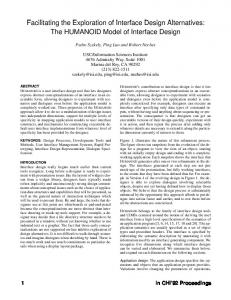
FIG. 1. 共a兲 Hysteresis loops of differently Nb-donor-doped PZT films indicating good hysteresis properties. 共b兲 Imprint behavior of differently Nbdonor-doped PZT films indicating no influence of the donor dopant concentration 共PZT, 30:70, 150 nm, 25 °C兲.
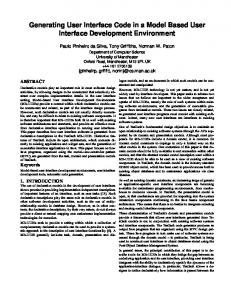
to Warren’s publication5 no significant influence of the Nbdonor doping on the imprint behavior of these films is observed 关Fig. 1共b兲兴. Although there is no significant influence of the Nb doping observed in the case of hysteresis and imprint measurement, the Nb concentration influences the switching behavior as well as the loss tangent of the same films.21 This behavior indicates that the Nb doping indeed has an influence on the ferroelectric behavior of PZT films but the imprint behavior is not affected. The discrepancies between the results presented in this work and the results obtained by Warren and Kim on similarly doped PZT films5,18 might indicate that depending on the preparation process in some ferroelectric thin films, the defect dipole alignment is the dominating mechanism. Figure 2共a兲 shows the hysteresis loops of differently Feacceptor doped PZT films. Again, nicely square loops are obtained for dopant concentrations up to 1 at. %. Even the 3 at. % Fe-doped PZT film exhibits a 2P r value exceeding 50 C/cm2 . Only a slight influence on the imprint behavior is observed 关Fig. 2 共b兲兴. The investigations on Fe-doped PZT films indicate that Fe doping has only a negligible impact on the hysteresis and imprint behavior of 150-nm-thick PZT films 共30:70兲. This independence of the Fe dopant concentration in the case of PZT thin films is in contrast to the influence of Fe doping in PZT ceramics. Carl demonstrated that Fe doping enhances the internal bias in PZT ceramics especially in the range between 0 mol % to approximately 1 mol % Fe doping.6 However, in the case of thin films no significant enhancement up to 3 at. % Fe doping is observed. Thus, adding acceptor and donor dopants to ferroelectric thin films leads to a contrary behavior compared to ferroelec-
Grossmann et al.
FIG. 2. 共a兲 Hysteresis loops of differently Fe-acceptor-doped PZT films indicating good hysteresis properties. 共b兲 Imprint behavior of differently Fe-acceptor-doped PZT films indicating no influence of the acceptor dopant concentration 共PZT, 30:70, 150 nm, 25 °C兲.
tric bulk material. In the case of thin films no significant influence is observed whereas the drastic enhancement due to acceptor doping in the case of bulk material indicates that defect dipole alignment is the dominating origin for the internal bias in these materials. The discrepancy between thin films under investigation and bulk material might be caused by the fact that the alignment of defect dipoles does not contribute a significant part to the imprint effect in the case of thin films. This conclusion is based on the assumption that the defect chemistry of titanate thin films is similar to that of titanate bulk ceramics. However, this does not necessarily have to be the case. The defect chemistry of titanate thin films has not been well understood. First approaches indicate that there are some similarities between bulk material and thin films but also distinct differences.22 However, another experimental result strongly suggests that defect dipole alignment is not the dominant process in the imprint scenario of ferroelectric thin films. Exposing the ferroelectric capacitor to illumination with UV light with an optical energy which exceeds the band gap of the ferroelectric thin film significantly enhances imprint for PZT thin films 共Fig. 3, see also Refs. 23 and 24兲. This result strongly indicates that electronic species such as electrons and holes are the dominant species in the imprint scenario of ferroelectric thin films since the mobility of oxygen vacancies in acceptor centers are not expected to be influenced by illumination. To summarize this section, ferroelectric thin films exhibit a distinctly different dependence on acceptor dopant concentrations compared to ceramics. This result, together with the significant enhancement of imprint due to illumination suggests that the defect dipole alignment is not the dominating process in the imprint scenario of ferroelectric
Downloaded 15 Dec 2006 to 134.94.122.39. Redistribution subject to AIP license or copyright, see http://jap.aip.org/jap/copyright.jsp
Grossmann et al.
J. Appl. Phys., Vol. 92, No. 5, 1 September 2002
2683
FIG. 3. Illumination with UV light exceeding the band gap of the ferroelectric thin films enhances imprint dramatically 共PZT 30:70, 200 nm, illuminated with ⫽302 nm at room temperature兲.
thin films under investigation. However, in contrast to this work, experimental results reported in the literature5,18 –20 reveal an influence of donor doping on the imprint behavior of PZT thin films. These results might indicate that depending on the quality and preparation of the ferroelectric thin films another imprint mechanism such as defect dipole alignment might be dominant in contrast to the PZT films investigated in this article. B. Bulk screening model
In PZT thin films, Dimos and co-workers23,25 showed with imprint experiments under illumination that electronic charges play a dominant role in the imprint scenario for PZT films since an enhancement of imprint was observed due to illumination. They attributed this effect to the charge generation caused by the illumination and a subsequent separation of these charges in the interior of the ferroelectric thin film. In ferroelectric materials with conducting electrodes the depolarizing field caused by the polarization charges is usually screened by free electronic charges on the electrodes. As a consequence, the depolarizing field is completely screened resulting in a zero electric field within the material if the polarization and screening charges are located at the same position. However, if a thin layer exists at the interface between electrode and ferroelectric in which the spontaneous polarization is absent the external screening charges and the polarization charges are spatially separated. This spatial separation gives rise to a residual depolarizing field, E Res in the interior.26,27 In the PZT films under investigation there is indeed experimental evidence of a thin surface layer with suppressed ferroelectric properties as proposed by the bulk screening model 关Fig. 4共a兲兴. The equivalent circuit consists of two capacitors in series 关Fig. 4共b兲兴, C fe and C if , respectively (C if includes both interfacial capacitors at the top and bottom electrode兲. According to Cillessen,28 the extension of the surface layer ␦ is assumed to be much smaller than the total film thickness d ( ␦ Ⰶd). Since the surface layer seems to be a general ferroelectric surface phenomenon and the film thickness exceeds its extension by far, it is assumed that ␦ is independent of the total film thickness. As a result, one capacitor 关C fe) in Fig. 4共b兲 depends on the film thickness while the other (C if) does not (C fe⫽ ⑀ 0 ⑀ feA/(d⫺ ␦ ), and C fe
FIG. 4. 共a兲 Sketch of the electroded structure consisting of the interfacial layers and the ferroelectric. 共b兲 Equivalent circuit with two capacitors (C if : interfacial capacitance; C fe : ferroelectric capacitance兲 in series. 共c兲 Reciprocal value of the equivalent capacitance per area C eff /A plotted versus the film thickness. From the intercept at d⫽0 the interfacial capacitance C if is determined.
⫽ ⑀ 0 ⑀ ifA/ ␦ , where A is the area of the capacitor, ⑀ fe and ⑀ if the dielectric constants of the ferroelectric and the surface layer兴. The capacitance which can be determined experimentally is C eff , which corresponds to the equivalent capacitance of the two capacitors (C fe and C if) in series. The equivalent capacitance can be expressed as 1 1 1 ⫽ ⫹ . C eff C fe C if
共1兲
Upon changing the total film thickness only C fe is affected while C if remains constant. Thus, according to Eq. 共1兲, the equivalent capacitance C eff 共reciprocal value兲 for different film thicknesses should reveal a straight line when plotted versus the sample thickness. The extrapolation to d ⫽ 0 should then yield the interfacial capacitance C if . In Fig. 4共c兲 the measured reciprocal capacitance density A/C eff is plotted versus film thickness for PZT thin films. It can be seen that a straight line is obtained. From the extrapolation to d⫽0 an interfacial capacitance can be determined, which indicates the assumption of a surface layer to be reasonable. C if /A amounts to approximately 700 fF/ m2 in the case of PZT 共30:70兲. In the literature, values of the same order of magnitude are reported for C if /A for similar materials like BaTiO3 , 共Ba,Sr兲TiO3 , and SrTiO3 thin films and ceramics (C if /A⫽160 fF/ m2 , . . . ,600 fF/ m2 . 29–32 In the model proposed by Dimos, the driving force for the charge separation is the residual depolarizing field, E Res 共Fig. 5兲. After the charges have been separated they become trapped at the electrode thin film interface and screen the ferroelectric polarization. If the time constant of the motion/ redistribution of these screening charges exceeds the switch-
Downloaded 15 Dec 2006 to 134.94.122.39. Redistribution subject to AIP license or copyright, see http://jap.aip.org/jap/copyright.jsp
2684
Grossmann et al.
J. Appl. Phys., Vol. 92, No. 5, 1 September 2002
IV. INTERFACE SCREENING MODEL
FIG. 5. Sketch of the bulk screening model with the driving force E Res .
ing time of the ferroelectric polarization by several orders of magnitude, these screening charges can cause an internal bias field which results in a shift of the hysteresis loop on the voltage axis. This model consistently explains the enhancement due to illumination since this effect could not be explained by the existing models discussed in the previous sections. Applying a bias during the imprint treatment in the direction of the polarization enhances imprint in the case of ferroelectric thin films 关Fig. 6共a兲兴. However, the externally applied bias in the direction of the polarization points in the opposite direction than the driving force of the bulk screening model E Res . Therefore, according to the bulk screening model the bias in the direction of the polarization should weaken the imprint effect rather than enhance it. Due to the discrepancy with respect to the bias dependence, it is concluded that the bulk screening model is not the dominating imprint mechanism in ferroelectric thin films. However, it could still contribute a minor part to the imprint effect.
In the previous sections different models have been discussed which have been used in literature as an explanation for the imprint effect in thin films or the internal bias in bulk materials. However, it was shown with experimental data that there is some evidence that they cannot explain the imprint effect in the ferroelectric thin films under investigation. The pronounced dependence on illumination strongly suggests that redistribution of electronic species is the cause for imprint in thin films. The bulk screening model23,25 explains imprint by the separation and subsequent trapping of electronic charges due to a thin surface layer. The concept of a thin nonferroelectric surface layer seems to be reasonable since many effects observed in ferroelectrics can be explained by the existence of such a layer. However, the bias dependence of imprint rules out E Res as driving force for imprint as it was proposed by the bulk screening model.33 The existence of a layer at the surface of ferroelectric materials was proposed by a number of investigators since it can explain a variety of anomalies in the behavior of ferroelectric materials. However, there is still some debate about the nature of these surface layers. It is believed that the surface layers are either space charge layers34 or exhaustion barriers35 or chemically or mechanically distorted layers which do not take part in the polarization reversal process but give rise to interface charges.36,37 Its existence seems to be confirmed by a number of different experiments, which can explain quite different ferroelectric phenomenons by the existence of such a layer in the case of ferroelectric bulk materials.36 – 41 More recent publications in the field of ferroelectric thin films explained the thickness dependence of the coercive field as well as of the switching properties of PZT thin films with the existence of such a surface layer.28,42– 45 Since the interfacial layer approach seems to be quite reasonable for many experimental observations, a model is introduced in the following which can qualitatively explain the experimental observations with respect to the imprint effect in ferroelectric thin films with the existence of such a surface or interface layer. A. Electric field in the surface layer
The surface layer causes a residual depolarizing field E Res in the interior of the film which is antiparallel to the polarization.23,26,27 E Res arises since the polarization charges and the screening charges are separated by the interface layer. Let us now consider the zero bias case, i.e., the case when a polarization state has been established but no additional bias is applied and the top and bottom electrode are shorted. In that case, imprint is observed for both SBT and PZT films. Due to the Maxwell equation
冖 FIG. 6. 共a兲 Applying a bias in the direction of the polarization enhances imprint. 共b兲 Hysteresis loop indicating the established state of polarization for an applied bias of 3 V 关PZT 共45:55兲 200 nm, room temperature兴.
Eds⫽0.
共2兲
E Res has to be compensated in order to fulfill Eq. 共2兲. As a result an electric field arises in the interior of the interface layer26 which points in the direction of the polarization 共see Fig. 7兲.
Downloaded 15 Dec 2006 to 134.94.122.39. Redistribution subject to AIP license or copyright, see http://jap.aip.org/jap/copyright.jsp
Grossmann et al.
J. Appl. Phys., Vol. 92, No. 5, 1 September 2002
2685
FIG. 8. 共a兲 Model structure consisting of a thin surface layer of the thickness ␦ and a ferroelectric layer of the thickness d⫺ ␦ . In the virgin state no charges are trapped at the interface between ferroelectric and surface layer 关 if(t⫽0)⫽0兴 共b兲 Charge distribution ( p : polarization charge, 0 : screening charge兲, 共c兲 displacement, and 共d兲 field as a function of the position x.
FIG. 7. 共a兲 Sketch of the bulk screening model with the driving force E Res . 共b兲 Interface screening model: enlargement of the interfacial region showing the driving force of the interface screening model, E if , in the surface layer.
This electrical field can cause emission of electronic charges from the electrode into the film or charge separation in the interior of the surface layer. If these charges become trapped at the interface between the ferroelectric and the surface layer they would also cause an evolution of an internal bias upon time, similar to the model of Dimos, however, based on a distinctly different driving force (E if instead of E Res). If we now apply an additional bias in the direction of the polarization, this external bias would point in the same direction as the electrical field at the interface E if , and hence, the enhancement of the imprint behavior due to an external bias could be explained qualitatively since E if is expected to be increased due to superimposition with the external bias. Furthermore, at the interface between surface layer and undisturbed ferroelectric bulk two electric fields point in opposite directions (E if and E Res) which results in a good trapping condition for electronic charges at this position. The interface screening model can qualitatively explain the bias dependence since the driving force E if and the externally applied bias point in the same direction. Also the illumination effect can be understood since the model is of electronic origin.
In the following the influencing parameters for the field in the surface layer, E if , are determined. Let us consider a sandwich structure consisting of a thin surface layer and a ferroelectric layer as illustrated in Fig. 8共a兲. The properties of the ferroelectric layer can be described by the displacement D fe , the spontaneous ferroelectric polarization P fe , the electric field E fe , and the dielectric constant ⑀ fe describing the nonferroelectric contributions to the total polarization. In the surface layer no spontaneous polarization is present. The surface layer can thus be described by D if , E if , and ⑀ if with the respective denotations as for the ferroelectric layer. In the virgin state, i.e., the ferroelectric is poled for the first time after having entered the ferroelectric phase, the polarization charges are completely screened externally. Thus, no charges are trapped at the interface between ferroelectric and surface layer 关( if(t⫽0)⫽0兴. From simple electrostatics it can be derived that the displacement D is continuous at the interface between surface layer and ferroelectric layer 共at x⫽d⫺ ␦ ). Div D⫽ if共 t⫽0 兲 ⫽0.
共3兲
Using Eq. 共3兲 the dielectric displacement in the surface layer equals the displacement in the ferroelectric layer, D if ⫽D fe . The displacement in the ferroelectric layer can be expressed as D fe⫽ P fe⫹ ⑀ 0 ⑀ feE fe with E fe being the residual depolarizing field E Res in Fig. 7 with reversed sign E fe⫽ ⫺E Res . Furthermore, the dielectric displacement in the surface layer amounts to D if⫽ ⑀ 0 ⑀ ifE if . Using these correlations the field in the surface layer can be expressed as E if⫽
P fe⫺ ⑀ 0 ⑀ feE Res . ⑀ 0 ⑀ if
共4兲
Using the second Maxwell equation 关Eq. 共2兲兴 a correlation between E if and E Res can be obtained: E if⫽E Res
d⫺ ␦
␦
.
共5兲
Combining Eqs. 共4兲 and 共5兲, the field in the surface layer in the virgin state can be expressed as a function of the ferroelectric polarization: E if⫽ P fe
A 1 . C if⫹C fe ␦
共6兲
Downloaded 15 Dec 2006 to 134.94.122.39. Redistribution subject to AIP license or copyright, see http://jap.aip.org/jap/copyright.jsp
2686
Grossmann et al.
J. Appl. Phys., Vol. 92, No. 5, 1 September 2002
Hence, it can be qualitatively understood that the bias dependence is more pronounced for SBT thin films. The experimental observations presented in this section indicate that Eq. 共6兲 is a reasonable assumption, which suggests that the ferroelectric polarization is indeed the driving force for imprint. It might also explain why imprint in PZT films is significantly more pronounced than in SBT films since the polarization values of PZT films exceed those of SBT by a factor of 3 to 4. V. CONCLUSIONS
FIG. 9. PZT films with a different Zr:Ti ratio: 共a兲 Hysteresis measurement: the remanent polarization increases with increasing Ti content. 共b兲 Imprint measurement: imprint is more pronounced for higher Ti contents 共PZT, 200 nm, room temperature兲.
Equation 共6兲 shows that E if depends linearly on the ferroelectric polarization.
In this article the imprint behavior of PZT thin films is comprehensively addressed. The experimental results have been compared to the predictions of imprint models proposed in the literature. Due to the discrepancies between the predictions and the experimental results it is concluded that these models do not describe the dominating imprint mechanism in ferroelectric thin films. Hence, with the interface screening model an imprint model is proposed. This model suggests the imprint phenomenon to be caused by a large electric field within a thin surface layer at the electrode-thinfilm interface. The electric field arises due to damaged ferroelectric properties of the surface layer compared to the properties of the bulk of the film. With the interface screening model the experimental results presented in this work, such as the enhancement of imprint due to an external bias and due to illumination, can be qualitatively understood. ACKNOWLEDGMENTS
B. Impact of the remanent polarization and external biasing
In PZT it is known that the value of the remanent polarization increases with increasing Ti content 关see Fig. 9共a兲 and Refs. 46 and 47兴. According to Eq. 共6兲 a larger field in the surface layer is expected for higher Ti content assuming identical extensions of the layer. A larger field in the surface layer predicts imprint to be more pronounced. Also this prediction of Eq. 共6兲 is experimentally verified. Fig. 9共b兲 depicts the imprint behavior of PZT films with varying Ti content. Imprint is indeed more pronounced for the film with the highest Ti content, i.e., the largest value of remanent polarization. Based on Eq. 共6兲 the enhancement of imprint due to an externally applied bias in the direction of the polarization can be qualitatively understood. Applying an additional bias increases the polarization 关see, for example, Fig. 9共a兲兴 resulting in an increase of E if . In SBT thin films, the bias dependence is more pronounced than in PZT thin films 关compare Fig. 6共a兲 and Ref. 48, Fig. 3共a兲 therein兴. This difference might be caused by the different shape of the hysteresis loops. In the case of SBT the hysteresis loops are usually more slanted compared to PZT, which often exhibit nicely square hysteresis loops, especially in the case of Ti-rich compositions. Thus, the increase of the actually established polarization caused by the application of a bias is more pronounced in the case of a slanted hysteresis loop compared to a square one. In case of a square hysteresis loop, the established polarization is barely modified by an application of an additional bias.
The authors would like to acknowledge Professor G. Arlt from University of Aachen, R. Bruchhaus, N. Nagel, W. Hartner, G. Schindler, and M. Kastner from Infineon Technologies for fruitful discussions. Furthermore, the authors are indebted to F. Fitsilis, O. Baldus, and W. Krasser for their assistance in conducting the XRF measurements and the experiments under illumination and R. Gerhardt for the support of the sample preparation. This work was supported by the German Ministry of Education and Research BMBF 共Contract No. 03N60075兲. J. Scott and C. P. de Araujo, Science 246, 1400 共1989兲. S. Eaton, D. Butler, M. Parris, D. Wilson, and H. McNeillie, Dig. Tech. Pap.-IEEE Int. Solid-State Circuits Conf. 共1988兲, p. 130. 3 C. P. de Araujo, J. Cuchiaro, L. McMillan, M. Scott, and J. Scott, Nature 共London兲 374, 627 共1995兲. 4 W. Warren, D. Dimos, and R. M. Waser, MRS Bull. July, 40 共1996兲. 5 W. Warren, B. Tuttle, D. Dimos, G. Pike, H. Al-Shareef, R. Ramesh, and J. Evans, Jpn. J. Appl. Phys., Part 1 35, 1521 共1996兲. 6 K. Carl and K. Ha¨rdtl, Ferroelectrics 17, 473 共1978兲. 7 S. Takahashi, Ferroelectrics 41, 143 共1982兲. 8 G. Arlt and H. Neumann, Ferroelectrics 87, 109 共1988兲. 9 R. Lohka¨mper, H. Neumann, and G. Arlt, J. Appl. Phys. 68, 4220 共1990兲. 10 U. Robels and G. Arlt, J. Appl. Phys. 73, 3454 共1993兲. 11 N. Chan, R. Sharma, and D. Smyth, J. Am. Ceram. Soc. 65, 167 共1982兲. 12 N. Chan and D. Smyth, J. Am. Ceram. Soc. 67, 285 共1984兲. 13 D. Smyth and R. Waser, in Non-Metallic Solids, edited by J. Scott 共Gordon and Breach, New York, 1995兲. 14 R. Waser, T. Baiatu, and K. Ha¨rdtl, J. Am. Ceram. Soc. 73, 1645 共1990兲. 15 R. Waser, T. Baiatu, and K. Ha¨rdtl, J. Am. Ceram. Soc. 73, 1654 共1990兲. 16 T. Baiatu, R. Waser, and K. Ha¨rdtl, J. Am. Ceram. Soc. 73, 1663 共1990兲. 17 F. A. Kro¨ger and H. J. Vink, in Solid State Physics, edited by F. Seitz and D. Turnbull 共Academic, New York, 1956兲, Vol. 3, p. 307. 1 2
Downloaded 15 Dec 2006 to 134.94.122.39. Redistribution subject to AIP license or copyright, see http://jap.aip.org/jap/copyright.jsp
Grossmann et al.
J. Appl. Phys., Vol. 92, No. 5, 1 September 2002 18
S.-H. Kim, D.-J. Kim, J. Hong, S. Streiffer, and A. Kingon, J. Mater. Res. 14, 1371 共1999兲. 19 S.-H. Kim, D.-S. Lee, C. S. Hwang, D.-J. Kim, and A. I. Kingon, Appl. Phys. Lett. 77, 3036 共2000兲. 20 S.-H. Kim, H.-J. Woo, J. Ha, C. S. Hwang, H. R. Kim, and A. I. Kingon, Appl. Phys. Lett. 78, 2885 共2001兲. 21 O. Lohse, M. Grossmann, D. Bolten, U. Boettger, and R. Waser, Mater. Res. Soc. Symp. Proc. 655, 7.6.1 共2001兲. 22 C. Ohly, S. Hoffmann, K. Szot, and R. Waser, Integr. Ferroelectr. 33, 363 共2001兲. 23 D. Dimos, W. Warren, M. Sinclair, B. Tuttle, and R. Schwartz, J. Appl. Phys. 76, 4305 共1994兲. 24 M. Grossmann, S. Hoffmann, S. Gusowski, R. Waser, S. K. Streiffer, C. Basceri, C. Parker, S. Lash, and A. Kingon, Integr. Ferroelectr. 22, 83 共1998兲. 25 D. Dimos, W. Warren, and B. Tuttle, Mater. Res. Soc. Symp. Proc. 310, 87 共1993兲. 26 V. M. Fridkin, Photoferroelectrics, Solid State Sciences 共Springer, Berlin, 1979兲. 27 V. Shur and E. Rumyantsev, Ferroelectrics 191, 319 共1997兲. 28 J. Cillessen, M. Prins, and R. Wolf, J. Appl. Phys. 81, 2777 共1997兲. 29 M. H. Frey, Z. Xu, P. Han, and D. Payne, Ferroelectrics 206-207, 337 共1998兲. 30 H.-M. Christen, J. Mannhart, E. Williams, and C. Gerber, Phys. Rev. B 49, 12 095 共1994兲. 31 T. M. Shaw, Z. Suo, M. Huang, E. Liniger, R. B. Laibowitz, and J. D. Baniecki, Appl. Phys. Lett. 75, 2129 共1999兲.
2687
S. Streiffer, J. Appl. Phys. 86, 4565 共1999兲. M. Grossmann, O. Lohse, D. Bolten, R. Waser, W. Hartner, G. Schindler, C. Dehm, and N. Natel, Mater. Res. Soc. Symp. Proc. 541, 269 共1999兲. 34 W. Ka¨nzig, Phys. Rev. A 98, 549 共1955兲. 35 S. Triebwasser, Phys. Rev. A 118, 100 共1960兲. 36 M. Drougard and R. Landauer, J. Appl. Phys. 30, 1663 共1959兲. 37 R. Miller and A. Savage, Jpn. J. Appl. Phys. 31, 662 共1960兲. 38 A. Chynoweth, Phys. Rev. A 102, 705 共1956兲. 39 A. Chynoweth, Phys. Rev. A 117, 1235 共1960兲. 40 F. Jona and G. Shirane, Ferroelectric Crystals, Solid State Physics 共Pergamon, New York, 1962兲. 41 W. Merz, J. Appl. Phys. 27, 938 共1956兲. 42 P. Larsen, G. Dormans, D. Taylor, and P. van Veldhoven, J. Appl. Phys. 76, 2405 共1994兲. 43 A. Tagantsev, M. Landivar, E. Colla, and N. Setter, J. Appl. Phys. 78, 2623 共1995兲. 44 G. Haertling, Integr. Ferroelectr. 14, 219 共1997兲. 45 A. Tagantsev and I. Stolichnov, Appl. Phys. Lett. 74, 1326 共1999兲. 46 M. J. Haun, E. Furman, S. J. Jang, and L. E. Cross, Ferroelectrics 99, 63 共1989兲. 47 B. Tuttle, J. Voigt, D. Goodnow, D. Lamppa, T. Headley, M. O. Eatough, G. Zender, R. Nasby, and S. Rodgers, J. Am. Ceram. Soc. 76, 1537 共1993兲. 48 M. Grossmann, O. Lohse, D. Bolten, R. Waser, W. Hartner, G. Schindler, C. Dehm, N. Nagel, V. Joshi, N. Solayappan, and G. Derbenwick, Integr. Ferroelectr. 22, 95 共1998兲. 32 33
Downloaded 15 Dec 2006 to 134.94.122.39. Redistribution subject to AIP license or copyright, see http://jap.aip.org/jap/copyright.jsp