. WWW: http://www.usenix.org ... VM's were interpreter plus template generated code, and finally
USENIX Association
Proceedings of the Java™ Virtual Machine Research and Technology Symposium (JVM '01) Monterey, California, USA April 23–24, 2001
THE ADVANCED COMPUTING SYSTEMS ASSOCIATION
© 2001 by The USENIX Association All Rights Reserved For more information about the USENIX Association: Phone: 1 510 528 8649 FAX: 1 510 548 5738 Email:
[email protected] WWW: http://www.usenix.org Rights to individual papers remain with the author or the author's employer. Permission is granted for noncommercial reproduction of the work for educational or research purposes. This copyright notice must be included in the reproduced paper. USENIX acknowledges all trademarks herein.
The Java HotSpotTM Server Compiler Michael Paleczny Christopher Vick Cliff Click
Sun Microsystems 901 San Antonio Road, Palo Alto, CA 94303 {michael.paleczny,christopher.vick,cliff.click}@eng.sun.com Abstract The Java HotSpot Server Compiler achieves improved asymptotic performance through a combination of ob− ject−oriented and classical−compiler optimizations. Aggressive inlining using class−hierarchy analysis reduces function call overhead and provides opportunities for many compiler optimizations. TM
1. Introduction Performance for the Java Platform has evolved in stages. Early VM’s were interpreter−only. Later VM’s were interpreter plus template generated code, and finally interpreter plus optimized code. The Java HotSpot Virtual Machine improves performance through optimization of frequently executed applica− tion code. The Client version provides very fast com− pilation times and a small footprint with modest levels of optimization. The Server version applies more ag− gressive optimizations to achieve improved asymptotic performance. These optimizations include class−hier− archy aware inlining, fast−path/slow−path idioms, global value−numbering, optimistic constant propaga− tion, optimal instruction selection, graph−coloring register allocation, and peephole optimization. TM
TM
The first section describes the runtime environment that both the compiler and generated code execute within. Section two summarizes the structure of the server compiler. Sections three through section sev− enteen cover each phase of compilation in order. So− lutions for specific language and runtime issues are described close to the compilation phase that addresses them. Last is a short description of phase costs and performance of generated code. Some names that oc− cur in the compiler’s source code are used within the text for readers who download the source under Sun’s Community Source License [HS2.0]. The first occur− rence of these names is emphasized to avoid confu− sion.
2. Runtime Environment The server compiler generates code to execute within a runtime environment that also supports interpreter−
only, Core, and interpreter plus client compiler exe− cution. The runtime environment provides services which impact the performance of both compilation and the generated code. Several of the most significant features are: a single native stack per running thread for interpreting and executing compiled or native code, accurate garbage collection using card−marks, exception handling, efficient synchronization using a meta−lock [ADGKRW00] [BKMS98] [B98], class− hierarchy analysis, compilation events, on−stack re− placement of interpreter frames with compiled−code frames, deoptimization from compiled code back to the interpreter, a compiler interface that supports compilations in parallel with garbage collection, and runtime support routines which may be generated at system startup. The runtime generates the interpreter at startup using macro assembler templates for each bytecode and an interpreter dispatch loop [G99]. This provides assem− bly level instrumentation that collects counts at method entry and backward branches, type−profiles at call sites, and never−null object pointers for instanceof or checkcast bytecodes. Additional instrumentation has been implemented, e.g., branch frequencies, but is not turned on by default. The runtime environment uses adaptive optimization to focus compilation efforts on performance critical methods [HU96]. These methods are identified using method−entry and backward−branch counters with additional heuristics that investigate the caller of a triggering method. When the combined method−entry and backward−branch counters for a method exceed the CompileThreshold, the runtime system determines which method to make the root of a compilation by
examining the call stack. If the caller frequently in− vokes the callee, the recompilation policy may decide to start compiling at the caller. This upwards traversal may continue multiple times relying upon the compiler to inline the path to the triggering method. Compiled code for the standard entry point is registered with the method object (methodOop) in a reserved field. At method invocation, the interpreter transfers control to compiled code when this field is not null. A different transition, on stack replacement, occurs when a method’s combined counter exceeds the OnStackRe− placeThreshold at a backward branch. The method is compiled with an entry point at the target of the back− wards branch. The resulting code is registered with the methodOop, which contains a linked list of target bytecode index and compiled−code pairs. The runtime transfers execution from the interpreted frame to an on−stack−replacement frame and compiled code. The methodOop is used to cache other information as well, including the possibility that the compiler has refused to generate code for a method. A non−compilable method will always be run within the interpreter. This is used to support porting and debugging.
3. Compiler Overview The server compiler proceeds through the following traditional phases: parser, machine−independent opti− mization, instruction selection, global code motion and scheduling, register allocation, peephole optimization, and code generation. The compiler’s intermediate representation (IR) is a static single assignment graph (SSA) based on the work done by Click and Paleczny [IR95]. It is used throughout optimization, conversion to machine in− structions, scheduling, and register allocation. Opera− tions are represented by nodes which have an ordered tuple of use−def edges pointing to nodes that produce values it requires. Both data and control flow are rep− resented with explicit edges. When control−flow paths merge, e.g., after the body of an if statement, a Re− gionNode is built to merge the control edges. Values modified along these control paths are merged by a PhiNode, which has an edge to the RegionNode and a sequence of edges for the inputs. The order of these inputs corresponds to the order of control inputs to the RegionNode. In practice, the parser only builds re− gions and phis where control flow paths merge, not at the start of each basic block. In the resulting structure, values often flow directly from definition to use and not through control flow. This simplifies sparse analysis and optimization but additional structure is required to describe information resulting from control decisions. An example is the information that an ob− ject reference is null on one path after an explicit null− check and not−null on the other. To add information
to a type we insert a new definition Check− CastPPNode during parsing. This retains the infor− mation until the value is merged into a phi. In addi− tion to null, not−null, and the object hierarchy, the type system handles primitive types and the control type. During a non−optimistic analysis phase, a "TOP" control input immediately signals that this control flow path is dead.
4. Parser The parser’s first pass over the bytecodes identifies basic blocks and their predecessors. The second pass visits basic blocks and for each block translates each bytecode to the compiler’s IR. The basic block pars− ing order will visit a block whose predecessors have been parsed before a block with unparsed predecessors whenever possible. This makes type propagation dur− ing parsing as beneficial as possible without requiring backtracking. After parsing has completed, def−use edges are constructed in a batch pass to eliminate any useless code produced by the parser. These def−use edges are maintained during optimization until a ma− chine−specific representation is constructed. Since there are bytecodes at both low and high levels of abstraction, the number of nodes in the IR used to represent a bytecode varies widely. The bytecode iload_ does not require any IR construction be− cause the parser tracks the status of locals, expression stack, and monitors in a JVMState object. We trans− late this by updating an entry in the current JVMState object such that its top of the expression stack contains a pointer to the indicated local. Other low−level nodes require the construction of one or more IR nodes. An example of this is iadd where two entries are popped off the JVMState expression stack and AddINode is built. This node has a null control edge and two inputs, pointers to the nodes that were popped off the expression stack. Before pushing the result onto the JVMState’s expression stack the AddINode is optimized. The optimizations applied during parsing, Ideal, Value, Identity, GVN, are a subset of those ap− plied during post−parse optimization since def−use information is not available. Ideal canonicalizes the node structure locally and upwards along use−def edges. It may reorder the inputs to a commutative op− eration like AddINode to support value−numbering or even construct replacement nodes as in the conversion of (constant + (constant + variable)) to (variable + (constant + constant)). Value performs abstract inter− pretation to produce a type for the result of this node. This transformation constant folds (constant + con− stant) to (constant). Identity recognizes when the re− sult is equivalent to one of its inputs and returns that input instead. This transformation cleans up (variable + zero). Finally, global value numbering checks a
hash table to see if this node’s value is already re− corded. If it is, the node that previously produced it is returned and the newly constructed node is discarded. For new values we record the pair . When parsing a higher−level bytecode, instanceof, we apply the transformations to each node in turn. The generated IR first checks if the object is null. When the result of this check can be determined at parse− time, by inspecting the compiler’s type for the input, the never taken branch will not be constructed. For the not−null branch, we generate a fast/slow path id− iom. A fast/slow idiom is a diamond−shaped control flow graph (CFG) where the expected case is to do quick checks along the fast path to confirm a result. When some portion of the fast path fails, control transfers to the slow path which covers all remaining cases. For instanceof, the fast path checks a two−ele− ment class cache to see if this object’s class has re− cently been verified as being the desired instance. If this fails, the slow path calls a runtime routine that checks the subtype relationship and updates the cache as necessary. We did not implement a failure cache as preliminary investigation did not confirm a perform− ance improvement for common programs. Object allocation provides another example of a fast/slow idiom. The fast path has an atomic test and set of the heap top. If the new heap top is safe, fast− path allocation is complete. If it has exceeded the up− per limit for this memory space, execution continues to the slow path and the thread is stopped at a safepoint for garbage collection. Allocation of objects with fi− nalizers is also done by the slow path since finalizer registration is done within the runtime system. Addi− tional fast/slow path idioms are generated for check− cast, object array store, other types of object alloca− tion, and division by zero.
5. Uncommon Traps In HotSpot, we compile methods that have crossed a threshold. In most cases any necessary class initiali− zation or class loading has already been done by the interpreter which handles all initialization seman− tics. We investigated having the generated code han− dle class initialization properly and discovered that it is too rare. Instead the compiler generates an uncom− mon trap, a trampoline back to interpreted mode, when it compiles a reference to an uninitialized class. The compiled code is then deoptimized and it is flagged as being unusable. Threads entering the method are in− terpreted until its recompilation is finished. As a side effect, field offsets are always known so short−form addressing modes can be used without backpatching.
6. Call Sites All invokeX bytecodes are parsed in a single function, do_call, to keep related pieces of code together. do_call starts by checking that the destination method is loaded, its holder is initialized, and the return value is loaded. Failure at this point results in generating an uncommon trap instead of the call. After checking these safety conditions, do_call inlines the callee or generates one of two distinct calling mechanisms, static or dynamic. Static calls dispatch directly to the verified entry point of a method and are used for static calls and non−inlined virtual calls that have only one receiver. Dynamic calls dispatch to the unverified en− try point of a method and are preceded by an instruc− tion that places an inline cache holder in a register. The unverified entry point compares the dynamic re− ceiver’s class to the class in the inline−cache. If the unverified entry point fails then control transfers to a runtime routine to patch the call−site. Since any non− final virtual method may be invoked using this tech− nique, the inline−cache register is not used for passing normal arguments. Inline caches have been used for dynamic object−oriented languages since Smalltalk 80 [DS84]. Virtual and interface calls are examined to determine if there is only one receiver. First with class hierarchy analysis (CHA) and second with receiver profiling done during interpretation. If CHA identifies a single receiver the callee will either be inlined or called as an optimized virtual call using the static call mechanism. In these cases we record that this method is dependent upon the class hierarchy below the receiver class. A later class load could provide another implementation of the target method requiring deoptimization of the compiled code [HCU92]. The mechanism is described in the next section. Inlining recursively invokes the parser on the target method to generate an intermedi− ate representation of the callee with the type informa− tion at the call−site available as context. If CHA does not identify a single target but the receiver profiling record only has a single class as receiver, we generate runtime verification code and inline the target method. Unlike the approach taken by IBM [SOTYKIKN00], the failure path does not form a diamond containing the inlined method on one side and a virtual call on the other since the merge point would destroy the precise information gained by the explicit check. Instead the failure path generates an uncommon trap, resulting in deoptimization and recompilation of the method if the receiver changes. This is a modification of uncom− mon−branch−elimination [HU96] which normally clones the rest of the method for the infrequent path. A CheckCastPPNode is inserted to force the type of the receiver to the profiled type, eliminating the need for such checks later in the method.
Although inlining provides the most opportunity for optimization, making a virtual call has its own re− wards. A non−inlined virtual call does an implicit check that the receiver is not null. After these call− sites a CheckCastPPNode forces the callee−type to not−null. Exception paths are connected after either inlining or creating a call node. If inlined, all exceptions thrown by the callee are checked against a list of handlers in the caller. When a matching handler is available, the generated code verifies correctness and jumps directly to the handler. If the correct handler can not be iden− tifed, e.g., caller does not have a handler, the callee’s exception path becomes a rethrow and the runtime system finds the handler. Since exceptions are con− sidered infrequent, exception regions are not registered during normal execution as in [SOTYKIKN00]. Al− though this reduces the impact on non−exception throwing code, the runtime may have to traverse the stack to find a handler.
7. Deoptimization If class loading invalidates inlining or other optimiza− tion decisions, the dependent methods are deoptimized [HCU92]. Threads currently executing in the method are rolled forward to a safepoint, at which point the native frame is converted into an interpreter frame. The invalidating class load is not visible to the execut− ing thread until it has been brought to a safepoint. Execution of the method continues in the interpreter.
To avoid revisiting nodes that are already at a fixed point, the parser produces a worklist containing nodes that may benefit from additional transformations. The results of prior abstract interpretation are also provided as input to the next phase, iterative GVN. PhaseIt− erGVN applies a pessimistic sparse iterative algorithm until it reaches a fixed point. This is done after build− ing Def−Use edges and then forward propagating changes from Ideal, Value, Identity, and GVN trans− formations for all nodes on the worklist. As described, this will only reach a fixed point for optimizations that inspect their immediate definitions since an interme− diate node might not change value stopping the itera− tion. To ensure a fixed−point for transformations that inspect a node’s grandparents, the iteration inspects grandchildren for additional nodes that must be added to the worklist. Optimizations that use def−use infor− mation to inspect their children are not required for program correctness and are not guaranteed to reach a fixed−point. The next phase, PhaseIdealLoop, iterates until no "major" control−flow changes occur. Major changes occur in the following cases: a loop becomes dead; an ’if’ is removed because it is duplicated by a dominat− ing test; an ’if’ is cloned upward through a region. The cloning only occurs when at least one cloned "if" will fold away. This optimization is enabled by de− fault starting with the Solaris Kestrel Release. During this phase loop peeling removes null checks from in− side the loop.
8. Optimizer
The last pair of machine−independent optimizations re−apply constant propagation and iterative GVN until a fixed−point to perform global dead code elimination. The constant propagation algorithm is optimistic sparse conditional constant [WZ85] where forward propagation starts with each value initialized to TOP. Constant propagation also places some grandchildren on the worklist to support Value calls that examine their grandparents. This occurs for a CatchNode fol− lowing a call, which defines exception paths, since it examines not only the value of the call node but also the value of the receiver parameter. The standard re− turn path following the call is not enabled until after it is proven that the receiver input may not be null. Be− fore a call node is pushed onto the worklist its uses are examined to find the CatchNode and push it onto the worklist. A similar investigation is performed before placing a RegionNode onto the worklist since its value might not change when a control−flow input changes, but PhiNodes that depend upon it must update their value if a control−flow path becomes dead.
Since parsing attempts to visit a block after all of its predecessors, it is at loop headers that further progress from the set of parse−time optimizations is possible.
After constant propagation has reached a fixed point, nodes that have been identified as constant are re− placed in a recursive use−def traversal that updates
Deoptimization, therefore, requires that we can regen− erate the interpreter’s JVM state at various points in the program. This is very much the same information required to debug optimized code. We do this by re− cording the exact JVM state as inputs to safepoints and procedure calls. The entire JVM state is thus "live" into the safepoint. We then allow the optimizer and register allocator to do their best with this JVM state information. Finally, during code emission we build a table mapping the JVM state to the final resting place of the still−alive JVM state information. The result is well optimized (but not perfectly well optimized) code with exact JVM semantics at specified program points. The result of keeping JVM state around is that some extra values remain "live" longer. These long−lived values generally spill to the native stack frame and have no more cost than an extra store in the final code.
both use−def and def−use information. During this traversal any control dependence information main− tained by cast−nodes, e.g., CheckCastPPNode, is transferred to memory operations that use the address. This allows safe removal of unnecessary cast−nodes in the next GVN pass. In addition, a worklist is gener− ated so the following iterative GVN pass does not ex− amine the entire program. The worklist is initialized with nodes that use the newly discovered constants. It also contains "if", "region", and "loop" nodes plus conversions from integer to boolean and pointer to boolean. These nodes are likely to benefit from the optimistic type information generated during constant propagation. In particular, null checks benefit from improved null/not−null type information.
9. Instruction Selection Translation from machine−independent instructions to machine instructions uses a bottom−up rewrite system, BURS [PLG88]. This is done before placing instruc− tions into basic blocks so that the selection is unen− cumbered by block boundaries. Before translation the sea−of−nodes that exists during optimization is di− vided into possibly overlapping subtrees by labeling each subtree’s root node. Subtree root candidates are nodes with multiple users and nodes that may not be duplicated because of side−effects, e.g., the atomic add idiom for memory allocation. By convention a root produces its result in a register so the value may be shared without recomputation. Shared nodes that are not labeled as roots are reached by multiple paths producing duplicate computation. Root selection is preferenced to only duplicate address expressions and other idioms that the machine architecture can sub− sume into one instruction. Nodes that are not trans− lated to machine instructions, e.g., PhiNodes, are re− corded in a dontcare array. Machine specific nodes for each subtree are generated in two steps. First a postorder walk along use−def edges starts from a selected root and visits all children recursively unless the child is a root, is not matchable, or has a different control input than the walk. When visited, the node and the possible translations of its children, recorded in a State object, are passed to a deterministic finite automata (DFA). The DFA rec− ords the lowest cost instruction for each possible result in a new state vector for use when the node’s parent is visited. This process provides optimal instruction se− lection within the constraints of subtree selection, ac− curate costs for machine instructions and operands, and available instructions in the architecture descrip− tion. The result of the postorder walk is a binary state tree identifying the least−cost instruction to generate at each level. Recursively traversing a state tree, the preorder visit generates the lowest execution−cost ma−
chine instruction for that level. The postorder visit at− taches the instructions generated for its inputs. Addi− tional edges are inserted for machine−independent in− formation including memory and control.
10.Global Code Motion The framework used to place instructions into basic blocks is a modified version of that described in [C95]. Our first step is to build a control flow graph skeleton of basic blocks. Virtual calls for is_block_start and is_block_proj identify nodes that start and end blocks respectively. Since the sea−of− nodes representation does not contain a block start or region node for each block, one is constructed where necessary. Next we compute dominator information for each block using the algorithm by Lengaur and Tarjan [LT79]. Block frequency estimates are gener− ated using two forward passes. The first does forward propagation from method−start in reverse postorder scaling loop header frequency upwards by ten and splitting frequency at ifs using the probabilities re− corded during parsing. The second pass updates block frequencies using information from all predecessors instead of only the depth first path from start. This propagates information around loops. An additional update done during the second pass sets the block fre− quency of any block ending with a halt instruction to medium−rare. We assign instructions to blocks in three stages. The first stage identifies the earliest legal block for each instruction. This is done recursively by examining the earliest legal block for each input and finding the one which is deepest in the dominator tree. The base cases are provided by the nodes pinned into the basic block skeleton which include: Start, Region, Phi, Goto, and Return. The second stage identifies the latest legal block for each instruction during a depth−first walk over def−use edges. The def−use information used during optimization was lost when new machine−spe− cific nodes were generated so it is rebuilt at the start of scheduling. The depth−first walk’s postorder visit to a node computes its latest legal placement as the least common ancestor of all uses. If the node is a store to memory we insert any required anti−dependence edges, an edge from the store to a load that must pre− cede it. Control−flow and memory alias analysis are used to identify loads and stores that are independent, known to access distinct memory locations, allowing more scheduling freedom. This late insertion of anti− dependence edges requires that the depth−first walk visit all children which may be loads after their sib− lings. A store can fail to schedule if a load that must precede it has been placed into too late a block. Stage three selects a block between the earliest and the latest legal location by walking up the dominator tree and
identifying the block with least frequency. This is done during the postorder visit after computing the latest−legal block and inserting required anti−depend− ence edges.
11.Local Scheduler The local scheduler orders instructions internal to a basic−block by selecting from a worklist of ready nodes and placing the selected instruction at the next available position. An instruction is placed on the ready list when all of its inputs within the block have been selected. Inputs from instructions in different blocks are not considered. The select routine com− putes a score for each ready instruction and returns the one with the highest score. The initial score is deter− mined by several heuristics (e.g., nodes that only have uses outside the current block start with a lower score to encourage scheduling them late.) An instruction that stores to memory or the stack is given a higher initial score to free any registers its inputs may be us− ing. The initial score is biased to delay loads and pre− fer instructions with many inputs.
12.Global Register Allocator The register allocator is structured in three phases. The first phase converts the SSA based CFG into non− SSA form (SSA structure is also retained at this point for use in the allocator.) The second phase is the main allocation loop, which is fundamentally a Briggs− Chaitin Graph Coloring Global Register Allocator with a number of refinements for both allocation speed and code quality. The third phase is a cleanup phase which manifests and cleans up the instructions generated by the allocator, and records Garbage Collection infor− mation. Our allocator has a number of special features. We use our allocator to perform the normal duties of a calling convention module. That is, our calling con− vention merely specifies the legal registers for values which flow into calls, and we allow the allocator to generate any necessary instructions to move the values to the appropriate locations prior to the call. In addi− tion, we use the allocator to allocate locations on the hardware stack frame as if they were registers, thus minimizing frame size. We also replace standard stack based spilling for live ranges which fail to color, with a special form of live range splitting. Finally, we use the allocator to generate the information necessary to perform garbage collection during execution of the compiled code.
13.Reverse SSA Transform Since our IR uses an SSA based structure, we must
have a phase in the compiler which converts from the SSA form of the program to the non−SSA form. We have chosen to integrate this phase with the Register Allocator. We perform a pass over the CFG which in− serts "virtual copies" at phi node sites. These "virtual copies" are virtual in the sense that we do not fully in− sert the nodes into the graph until later. We then per− form global live analysis on the annotated CFG, and gather information about the legal set of registers for each live range. Using that information, we construct an "interference graph" (IFG) for the method. The IFG represents the analysis of which live ranges "in− terfere", that is, could compete for the same registers. We then use the IFG to perform a pass of copy coa− lescing. This pass is aggressive in the sense that it could remove a copy which we will later have to rein− sert, but it is pessimistic in the sense that it assumes that copies are necessary, and attempts to prove that they are not. This special coalescing pass only works on the virtual copies inserted during the reverse SSA transform. Any virtual copies which remain after the aggressive coalescing pass are then converted to actual copy instructions in the CFG. The CFG then contains the non−SSA version of the method, while the normal IR version of the method is also retained with its SSA form and phi nodes. This dual representation allows us to perform SSA based analysis and optimizations while ensuring that we allocate all the copies neces− sary to restore normal naming. Finally, we execute a pass over the CFG which inserts extra uses of object pointers which serve as the base of a derived pointer. These extra uses are added at safepoints in order to ensure that the base object pointer values are still live and available at the safepoint location so that the gar− bage collector can inspect and relocate them.
14.Main Allocation Loop The principal work of register allocation is performed in an iterative loop. We perform live analysis, gather the legal register sets for the live ranges, and build an IFG for the method. Then we perform a conservative pass of copy coalescing (i.e., we only coalesce where we can prove that removing the copy will not force another interfering live range to fail to color.) This pass is followed by the standard simplification and color selection phases of a graph coloring alloca− tor [BCT94]. Finally, if we fail to color all live ranges, we perform a transform which splits any live range which failed to get a color into a series of smaller live ranges connected by copies. Then the process repeats until a complete coloring is found. Our implementation of a graph coloring allocator has a few special features designed to improve the speed of the allocator as well as to improve the quality of the
code generated. During the construction of the IFG, we transform the legal register set for live ranges which interfere with what we call "bound" live ranges. Bound live ranges are those which are restricted to a single predefined register. A typical example of this is found in the arguments to a call which are passed in a register specified by the calling convention. Since these live ranges must color into that particular regis− ter, we remove that register from the legal register set of all live ranges which interfere with the bound live range, and which are not also bound. This signifi− cantly reduces the number of interferences in the IFG, and speeds the computation of the IFG. In addition, we also track a metric of "register pres− sure" during IFG construction. Each basic block is tagged with a value which indicates that the block has either high or low register pressure, and where in the block a transition from low to high pressure takes place. We use this information during our live range splitting pass. This pass performs a reaching defini− tions data flow propagation, inserting copies into any live range which failed to color at any point where that live range crosses a high register pressure boundary. The copies are tagged with a special legal register set which allows them to color onto the stack rather than in the hardware registers. This splitting has two bene− fits. It inserts fewer copies than splitting at every use and definition which speeds up copy coalescing and live analysis. In addition, since we split with a copy, the new live ranges could still color into registers even though the original unified range could not. This col− oring would include some register to register copies, which are far less expensive than loads and stores. These special features are more completely described in [CPV01].
15.Cleanup The third phase of the allocator performs several cleanup and bookkeeping functions. We remove un− necessary copies using a variant of register tracking to determine that a value that was split can actually live in a single location given the actual coloring assigned to the method. Then we gather and output the infor− mation necessary for garbage collection. This includes the location of all object pointers which are alive across a safepoint, as well as the location of all values which are callee saves in the method, and all necessary computation information for derived pointers which have an object pointer as their base. Finally, we per− form a pass which transforms our special copies which were inserted during live range splitting and which failed to be colored into a hardware register (i.e., they were colored onto the hardware stack frame), with the appropriate load or store instruction. This pass also performs a special optimization on CISC architectures
which attempts to combine these loads or stores into a direct memory reference with either a user or definer of the value being copied, which we refer to as "CISC spilling". This process produces the final version of the CFG which we use for output in the final phase of compilation.
16.Peephole Optimizer This optimization inspects each sequence of adjacent instructions to determine if the instructions may be re− placed by a better sequence [ASU86]. The machine independent portion of this optimization visits every instruction, and invokes its machine−dependent peep− hole optimization. This is a virtual call built by our portability framework from information in the archi− tecture description. The operands of instructions in the original sequence can be required to satisfy equality constraints to ensure the safety of the trans− formation. A commonly applied peephole on the IA32 platform is replacement of "MOV dest_reg, src_reg" followed by "INC dest_reg" with the single instruction "LEAL dest_reg, dest_reg + 1". The equality constraint requires that the destination of the move and the register being incremented are identical. The current implementation restricts the replacement to a single instruction. TM
17.Code Generation In addition to executable machine code, the code gen− erator also provides oopmaps, debug info, exception tables, relocation information, and an implicit−null check table for use by the runtime system. All of this information is associated with one or more native− code offsets from method entry. Oopmaps and debug info are associated with the offset to their safepoint. Oopmaps are generated during register allocation and the code generator simply packages this information for the runtime. Safepoints at which a deoptimization may occur also record debug info describing either the constant value or native storage location for monitors, locals, and expression stack entries. The storage loca− tion may be a register or a stack frame offset. An ex− ception handler table at each call−site maps the byte− code index for each handler to its handler’s offset. This table is used by the runtime system to vector ex− ceptions to the correct handler in generated code when the transition can not be determined at compile−time. Relocation information supports movement of the generated code from the buffer in which it is generated to its installed location in the CodeCache. The method’s implicit null check table contains each offset at which an implicit null check may occur, paired with the corrsponding handler’s offset.
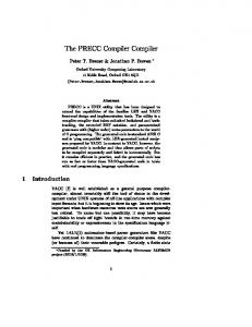
SPECjvm98 (test mode) on SPARC[tm] 100% 90%
Performance
80% 70% 60% 50% 40% 30% 20% Mtrt
Jess No Inlining
Compress Simple Inline
As a preliminary step to generating code and runtime− system tables, we calculate the size of the executable by sizing each instruction. While this is straightfor− ward on RISC architectures, time pressure and engi− neering simplicity led us to generate size information
Db No CHA
Mpegaudio
Jack
Javac
FCS_2.0
for CISC architectures by doing code generation twice. The first pass generates code for every instruction in a temporary buffer to calculate instruction size, basic block start/end, relocation size, reserve space for con− stants, and the return address for calls. With all sizes and offsets computed, we give branch
SPECjvm98 (test mode) on IA32[tm] 100% 90%
performance
80% 70% 60% 50% 40% 30% 20% Mtrt
Jess
No Inlining
Compress
Simple Inline
Db
No CHA
Mpegau− dio FCS 2.0
Jack
Javac
instructions their offsets. If the target architecture provides a shorter branch instruction format for local displacements, a replacement can be generated using the virtual method short_branch_version provided by the portability framework. Final code emission is done using the same MachNode::emit virtual used for the earlier size calculations, which emits raw machine object code into a buffer which is returned to the run− time system as the primary result of the compila− tion. The compiler interface relocates the generated code to the CodeCache and registers it with the meth− odOop.
18.Floating Point Precision On the IA32 architecture HotSpot normally executes with the FPU control word set for 53−bit precision and round to nearest. This means that when executing a non−strict method the result of each float operation must be restricted to 24−bit precision, generally by spilling to memory or the stack. Before performing instruction selection, we count the number of float, double, and invoke actions. When the following heu− ristic is satisfied we switch to 24−bit floating point mode: ( #doubles == 0 && #floats > 32 && #floats > 10 * #calls ). This mode modifies instruction selection such that individual floating point operations do not have to be spilled to the stack until assigned. In addi− tion, at method entry and upon return from any outgo− ing call the FPU control word will be set to 24−bit precision. Before every method exit point and every outgoing call the FPU control word is returned to the system’s default 53−bit precision. TM
19.Experimental Results The server compiler applies both object−oriented op− timizations, such as class hierarchy based inlining, and traditional compiler optimizations, such as memory alias analysis and global value numbering. The results for two target platforms are presented in bar charts with one column for each optimization per benchmark. Each column is normalized to the performance of the downloaded sources. The first pair of charts illustrates four variations in inlining; the second pair illustrates two compiler optimizations. These benchmarks are from the SPECjvm98 client suite [SPEC98]. The re− sults are from test mode execution, the benchmarks are run as a group from the command line, not in SPEC− compliant mode. The SPARC platform is a Sun Ultra 60 with the process bound to one of the 450MHz. UltraSPARC−II processors. The IA32 platform is a Dell Dimension XPS B866r with 256 MB memory. The inlining tests cover four variations. The first, no inlining, turns off all inlining during compilation. It also turns off the possibility of starting a compile at
the caller when a method’s counter reaches the acti− vating threshold. The second only allows inlining of accessor methods. The third uses the default inlining heruristics but does not inline virtuals since there may be multiple receivers. In addition, it does not inline a virtual call when the interpreter’s call−site profile has seen only one receiver. The results of these three tests are normalized to the performance of the default pa− rameters in the sources. All of the tests use inline caches to improve the efficiency of non−inlined vir− tual calls. The compiler optimization tests illustrate the applica− tion of two different optimizations, memory alias analysis and global value numbering. The first test, Alias0, does not use memory alias analysis to deter− mine when field accesses are made to distinct memory locations. In addition, accesses to the heap are serial− ized with respect to accesses to internal data struc− tures. The second, Alias1, distinguishes between ac− cesses to an object field, an array length, a class pointer in the object header, and a VM private mem− ory space. The default analysis further partitions memory using the class holder and offset for a field, the element type for an array, and additional distinc− tions for internal data. The fourth column for each benchmark uses the default alias analysis but disables global value numbering except for control structures and comparisons (which is required by implementation constraints). Inlining accessors shows a small improvement on all benchmarks except compress and db where the differ− ences are not significant. Larger improvements occur from more extensive inlining even without inlining virtual calls. On SPARC this provides a 20% im− provement for JESS while on IA32 it provides a 12% improvement for JACK. Inlining based on class hier− archy analysis almost doubles the performance of MTRT, but provides only minor imprevements to four benchmarks on SPARC and five on IA32. On most of the benchmarks, enabling inlining helps SPARC more than IA32. The heuristics that control this optimiza− tion are tuned for each platform, and the larger register set on SPARC allows additional inlining without hurt− ing register allocation. The compiler optimization results show that memory alias analysis improves performance by up to 17%. On both architectures the largest improvements occur in COMPRESS and MPEGAUDIO while three of the benchmarks are unchanged on both platforms. The intermediate level of alias analysis, Alias1, provides small improvements for those benchmarks which vary. The last column for each benchmark shows the per− formance when not using global value numbering, an optimization which commons together equivalent
SPECjvm98 (test mode) on SPARC[tm] 100% 90%
Performance
80% 70% 60% 50% 40% 30% 20% Mtrt
Jess
Compress Alias0
Alias1
subexpressions. One common source for these ex− pressions is array accesses. The largest benefit on both platforms is from MPEGAUDIO which does have fre− quent array accesses. Global value numbering pro− vides significant performance improvements on SPARC, it has less impact on IA32. While the dupli− cate expressions are present after optimization on both platforms, but simple array access expressions can be folded into a CISC load or store when converting to
Db FCS_2.0
Mpegaudio
Jack
Javac
NoGVN
machine instructions.
20.Experiences The server compiler emphasizes the quality of gener− ated code, relying upon the 80/20 rule to spend more time optimizing frequently executed code. This costs compilation time with the approximate breakdown be− ing 14% parser, 20% optimizer, 6% instruction selec−
SPECjvm98 (test mode) on IA32[tm] 100% 90%
performance
80% 70% 60% 50% 40% 30% 20% Mtrt
Jess
Compress Alias0
Alias1
Db FCS 2.0
Mpegaudio No GVN
Jack
Javac
tor, 7% scheduler, 49% allocator, 4% code generator. However, the resulting performance helps achieve a SPECjvm98 score of 81.4 on a Dell Dimension XPS B866r with 256MB memory [Spec98]. Source code for the Java HotSpot Virtual Machine is available for download under terms of Sun’s Community Source License [HS2.0]. TM
21.References [ADGKRW99] O. Agesen, D. Detlefs, A. Garthwaite, R. Knippel, Y. Ramakrishna, and D. White. An Effi− cient Meta−Lock for Implementing Ubiquitous Syn− chronization. In Proceedings of the ACM SIG− PLAN ’99 Conference on Object−Oriented Program− ming, Systems, Languages and Applications (OOPSLA ’99), pages 207−222, November 1999. [ASU86] A. V. Aho, R. Sethi, and J. D. Ullman. Compilers: Principles, Techniques, and Tools, Addi− son−Wesley Publishing Co., Menlo Park, CA (1986). [BCT94] P. Briggs, K. D. Cooper, and L. Torczon. Improvements to graph coloring register allocation. ACM Transactions on Programming Languages and Systems, 16(3):428−455, May 1994. [C82] G. J. Chaitin. Register allocation and spilling via graph coloring. SIGPLAN Notices 17, 6 (June 1982), 98−105. Proceedings of the ACM SIGPLAN ’82 Symposium on Compiler Construction. [IR95] C. Click, M. Paleczny. A Simple Graph−Based Intermediate Representation. In ACM SIGPLAN Workshop on Intermediate Representations (IR ’95), pages 35−49, Jan. 1995. [C95] C. Click, Combining Analyses, Combining Op− timizations. Ph.D. thesis, appendix, Rice University, 1995. [CPV01] C. Click, M. Paleczny, C. Vick. Interference Graph Trimming. Submitted to ACM SIGPLAN’01 Conference on Programming Language Design and Implementation, 2001. [BKMS98] D. Bacon, R. Konuru, C. Murthy, and M. Serrano. Thin Locks: Featherweight Synchronization for Java. In Proceedings of the ACM SIGPLAN ’98 Conference on Programming Language Design and Implementation, pages 258−268, June 1998. [B98] L. Bak, presentation on the HotSpot JVM, Panel: The New Crop of Java Virtual Machines. In Proceedings of the ACM SIGPLAN ’98 Conference on Object−Oriented Programming, Systems, Languages
and Applications (OOPSLA ’98), pages 179−182, Oc− tober 1998. [G99] R. Griesemer. Generation of Virtual Machine Code at Startup. In OOPSLA’99 Workshop on Sim− plicity, Performance and Portability in Virtual Ma− chine Design. [HCU92] U. Hölzle, C. Chambers, and D. Ungar. De− bugging Optimized Code with Dynamic Deoptimiza− tion. In ACM SIGPLAN’92 Conference on Program− ming Language Design and Implementation, pages 1− 12, Jun, 1992. [H93] U. Hölzle. A Fast Write Barrier for Genera− tional Garbage Collectors. In OOPSLA’93 Garbage Collection Workshop, pages 1−6, Oct, 1993. [HU96] U. Hölzle and D. Ungar. Reconciling Re− sponsiveness with Performance in Pure Object−Ori− ented Languages. In ACM Transactions on Program− ming Languages and Systems, 18(4):355−400, Jul, 1996. [HS2.0] Java HotSpot Virtual Machine 2.0. June 2000. http://www.sun.com/software/community− source/hotspot/download.html. TM
[IKY98] K. Ishizaki, M. Kawahito, T. Yasue, M. Takeuchi, T. Ogasawara, T. Suganuma, T. Onodera, H. Komatsu and T. Nakatani. Design, Implementa− tion, and Evaluation of Optimizations in a Just−In− Time Compiler. In ACM 1999 Java Grande Confer− ence. [LT79] T. Lengauer and R. E. Tarjan. A Fast Algo− rithm for Finding Dominators in a Flowgraph. In ACM Transactions on Programming Languages and Systems, 1(1):121−141, 1979. [PLG88] E. Pelegrí−Llopart and S. L. Graham. Opti− mal code generation for expression trees: an applica− tion BURS theory. In Proceedings of the Conference on Principles of Programming Languages (POPL’88), pages 294 − 308, 1988. [Spec98] SPECjvm98 Benchmarks. http://www.spec.org/osg/jvm98.
June 1, 2000.
[SOTYKIKN00] T. Suganuma, T. Ogasawara, M. Takeuchi, T. Yasue, M. Kawahito, K. Ishizaki, H. Ko− matsu, and T. Nakatani, "Overview of the IBM Java Just−in−Time Compiler" IBM Systems Journal, 39(1):175−193, Jan, 2000.
[THS98] O. Traub, G. Holloway, and M. Smith. Quality and Speed in a Linear−scan Register Alloca− tor. In Proceedings of the ACM SIGPLAN ’98 Con− ference on Programming Language Design and Im− plementation, pages 142−151, June 1998.