Apr 24, 2003 - preliminary control, data and call flow analysis on a given Java ..... posed of two method calls, which must be repre- sented separately.] .... the 22nd International Conference on Software Engineer- ing, Limerick, 2000. ... S4 if(args.length > 0){. S20 a = 6;. } C5 int a = Integer.parseInt(args[0]);. S21 b = 20;. C6.
The Java System Dependence Graph Neil Walkinshaw 24th April 2003 Technical Report: EFoCS-46-2003 Department of Computer and Information Science University of Strathclyde Livingstone Tower Glasgow, G1 1XH
has focused on and presents a practical approach to its construction. Ottenstein and Ottenstein first suggested that dependence graphs could be used for software engineering operations in 1984 [14]. They proposed a graph which was capable of representing a program consisting of a single block of sequentially executed code. To enable the application of these operations to multi-procedural programs, Horwitz et al. introduced the System Dependence Graph, which represents every procedure as an individual dependence graph. The procedure dependence graphs are linked to a central dependence graph, which represents the main program [9]. There have been several proposed modifications to the system dependence graph, attempting to enable the representation of object-oriented programs. Such approaches must be able to cope with properties such as polymorphism, dynamic binding and inheritance. Larsen and Harrold proposed a graph 1 Introduction capable of representing these features for C++ proAnalysing and representing software in terms of grams [11]. This was modified by Kovács et al. its internal dependencies is important for a vari- and Zhao, to enable the representation of Javaety of software engineering applications. These in- specific features such as interfaces, packages and clude operations such as slicing and the computa- single inheritance [10, 20]. Liang and Harrold also tion of program metrics. The program dependence augmented Larsen and Harrold’s graph to distingraph represents these dependencies, where vertices guish data members in parameter objects, eliminatare program elements and edges represent depen- ing superfluous dependencies at callsites and hence dencies between them [14]. There have been sev- increasing the accuracy of graph-based operations eral approaches to building graphs for different pro- [12]. This paper presents a Java-based graph that engramming paradigms and languages. The Java System Dependence Graph (JSDG) summarises aspects capsulates the benefits offered by the approaches of object-oriented programming that previous work mentioned above. It presents the graph construcAbstract The Program Dependence Graph was introduced by Ottenstein and Ottenstein in 1984 [14]. It was suggested to be a suitable internal program representation for monolithic programs, for the purpose of carrying out certain software engineering operations such as slicing and the computation of program metrics. Since then, Horwitz et al. have introduced the multi-procedural equivalent System Dependence Graph [9]. Many authors have proposed object-oriented dependence graph construction approaches [11, 10, 20, 12]. Every approach provides its own benefits, some of which are language specific. This paper is based on Java and combines the most important benefits from a range of approaches. The result is a Java System Dependence Graph, which summarises the key benefits offered by different approaches and adapts them (if necessary) to the Java language.
1
2 THE JSDG
tion from a practical perspective and provides an example which demonstrates that the approach presented is viable. Although dependence analysis is an established area, the JSDG enables static analysis to be carried out on a graph which will produce more accurate results than other static Java dependence graphs, because it can represent abstract classes which need not necessarily be interfaces and it can distinguish data members in parameter objects. The next section introduces the JSDG by presenting its individual components. Examples of various concepts which are included in the graph are taken from a single larger program which is given in the appendix. This is useful, because it puts the various individual illustrations into context. Section three analyses the graph from a more practical perspective. It identifies the steps needed for the construction of the graph. Section four analyses potential research areas that could benefit from the graph and introduces some practical problems that could arise if the represented program contains features such as threads and exceptions. Section five provides a conclusion and summary.
graph which is composed of such a large number of different types of nodes and edges. This can however be partially facilitated by interpreting the JSDG as a layered architecture, where certain vertices on one layer are visible only to adjacent layers [16]. Depending on the application the dependence graph is intended for, not all of the nodes and edge types are required. The complexity of the graph can be reduced depending on the context in which it is applied. For example, if we intend to slice the dependence graph, any nodes or edges concerned with Java interfaces can be omitted.
2.1 A Language-specific Representation
Object-oriented representations proposed by Larsen and Harrold and Liang and Harrold [11, 12] generate the dependence graph from C++. Several of the differences between C++ and Java require different edges or nodes in the graph. Its construction relies on the fact that it is possible to perform some preliminary control, data and call flow analysis on a given Java program, in order to build a skeletal ver2 The JSDG sion of the graph. Given that this framework is established, other nodes relating to the program strucThe abbreviation ‘JSDG’ is the same as the abbre- ture (e.g. method and class vertices) are added. The viation used by Zhao [20]. The difference is, that accuracy of any traversal algorithm which operates Zhao’s ‘JSDG’ stands for ‘Java Software Depen- on the JSDG (e.g. a slicing algorithm) depends on dence Graph’, and the ‘JSDG’ in this paper stands the accuracy of the flow analysis performed in the for ‘Java System Dependence Graph’. This can be preprocessing stage. seen as an extension to Zhao’s JSDG, where a different mechanism is implemented for dealing with polymorphism and the representation of abstract 2.2 Statements classes is extended beyond interfaces. A JSDG is a multigraph which maps out control and data dependencies1 between the statements A statement represents the lowest layer in the JSDG. of a Java program. Statements are categorised ac- It is an atomic construct representing a single excording to whether they contribute to the structure pression in the source code of the program. A of a program (i.e. they are headers representing statement representing a call to another method (a methods, classes, interfaces and packages) or the callsite) requires a special representation and is deprogram’s behaviour (i.e. they belong to a method scribed in section 2.4.1. Livadas and Croll suggest body). Each category is represented differently on that accuracy of a slice on a dependence graph could the graph. When these different graphs are com- be improved by increasing the granularity of the bined, they provide a graph-based program repre- SDG to parse-tree level [13]. sentation, which is suitable as a basis for a range of Java provides a more intuitive way to subdisoftware engineering applications. vide statements; when a Java program is comThe dependence graph is a complex construct piled, it is translated into an intermediate, platformand is intended as an internal program representa- independant format called the bytecode. There are tion, not a visual one. It is difficult to visualise a several bytecode manipulation and analysis tools 1A
�� � �
������
exists, if the execution of a statement B relies on the execution of a predicate statement A. A data control dependence dependence exists, if the execution of a statement B references a variable which is defined / modified in a statement A.
2
2 THE JSDG
2.3 Method Dependence Graph
available (e.g. Soot2 and BCEL3 ), which would make data and control flow analysis between individual bytecode instructions possible. For the sake of illustration, we will only consider the source-code statement level construction of the graph.
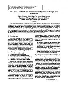
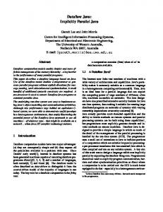
to the method entry vertex is represented by a dotted arrow. The actual-in vertices are connected to the formal-in vertices via parameter-in edges (dashed lines). The formal-out vertex is connected to the actual-out vertex via a parameter-out edge (dashed line). Data dependencies within the method (e.g. from c=c_in to int result = c + d) are represented by data dependence edges (dashed lines). A full legend for all of the examples featured in this paper is provided in appendix A.
2.3 Method Dependence Graph The method dependence graph (MDG) represents a single method or procedure in a program. It is the next layer up from the statement layer. MDGs are represented similarly in most OO dependence graph approaches [10, 11, 12, 20]. The method entry vertex is connected to any other vertices belonging to the method via control dependence edges. Parameter passing is modelled by introducing actual and formal variables. On the calling side, actual-in and actual-out vertices are tagged to copy each variable to and from its temporary location as required. The called method contains formal-in and formal-out vertices, which copy parameter variables from and to these temporary locations respectively. Parameter-in edges connect actual-in and formal-in vertices, while parameter-out edges connect formalout and actual-out vertices. Further formal vertices are connected to the method entry vertex to account for instance variables which may be referenced or modified during the execution of the method. All formal vertices are connected to the method entry vertex and all actual vertices are connected to the callsite via control dependence edges. The flow of data within a method, to its actual-in and formal-out vertices and from its actual-out and formal-in vertices, is indicated by data dependence edges. The call dependence edge indicates the link between the callsite and the method being called. Figure 1 illustrates an example of a simple method which adds two integers. To put this example into context, see the call from node C23 to E26 in appendix C. The method is represented by a method entry vertex (private int add(int c, int d)), which is connected to statement vertices (int result = c + d and return result) and formalin and formal-out vertices (c=c_in, d=d_in and result_out=result) via control dependence edges (plain arrows). The callsite (int added=add(a,b)) belongs to another method and is connected to its actual-in and actual-out vertices (c_in=a, d_in=b and added=result_out) via control dependence edges. The call dependence edge from the callsite
int added=add(a,b)
private int add(int c, int d)
c=c_in
d=d_in
int result = c + d
c_in=a
return result
d_in=b
added=result_out
result_out=result
Figure 1: Example of a simple method call (extracted from appendix - call from node C26 to E29)
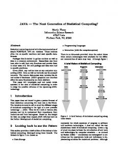
2.4 Class Dependence Graph The class dependence graph (ClDG) represents the classes in a program [11]. It is the next layer up from the MDG layer. For every class, there exists a class entry vertex, which is connected to the method entry vertices of its methods via class membership edges. These membership edges can be tagged as either public, protected or package (default) to indicate their visibility [10]. If one class inherits from another, they are linked by a class dependence edge. The class entry vertex is connected to its data members via data member edges. Figure 2 shows the ClDG of classes SimpleCalc and AdvancedCalc (see appendix B). Inheritance is indicated by the class dependence edge which passes between them. Note that although AdvancedCalc inherits all of the data members and methods belonging to SimpleCalc (apart from its constructors), it only needs to be linked to its own specific data members and methods. Inherited data members and methods can simply be computed by traversing up the class dependence edge and along the class membership / data member edges of SimpleCalc [10].
2 http://www.sable.mcgill.ca/software/ 3 http://jakarta.apache.org/bcel/
3
2 THE JSDG
2.4 Class Dependence Graph
public class SimpleCalc implements Calculator a
getStats(e) public int getA()
b
public SimpleCalc()
public int average()
public SimpleCalc(int aIn, bIn)
private int divide(int c)
public int getB()
e
public int multiply(int c, int d)
private int add(int c, int d)
SimpleCalc
public class AdvancedCalc extends SimpleCalc
public power()
public AdvancedCalc()
public AdvancedCalc(int aIn, int bIn)
a
public int multiply()
Figure 2: The ClDGs of the SimpleCalc and AdvancedCalc classes from appendix B (see nodes CE17 and CE46)
AdvancedCalc
b
b
a
Figure 4: Example of polymorphic parameter object (see node C11 in appendix)
2.4.1 Object Representation and Polymorphism
3. v is a callsite vertex and the method being called is defined in a statically typed object: Because the implementation of the method can be determined statically, the callsite can simply be expanded by adding the actual-in and actual-out vertices. Note that, although the method does not have any parameters, we still need to represent the object data members as actual-in vertices, because they represent the instance variables referenced by the method. Figure 5 illustrates a call to power() contained in the statically typed AdvancedCalc object.
The JSDG represents different instances of a class individually; this enables dependence graph operations such as slicing to take individual objects into consideration [12]. A statement vertex v which references an object is expanded into a tree depending on the context in which v is used. The examples (figures 3-6) are taken from the calculator example given in appendices B and C. The following four sections illustrate these possible expansions: 1. v is a parameter vertex representing a statically typed4 object: v is expanded into a tree. Figure 3 illustrates the callsite for getStats(e), given that it can only accept objects of the type AdvancedCalc.
e.power()
AdvancedCalc.power
computePower(e)
a
b
A1_out
AdvancedCalc e
a
b
Figure 5: Example of a call to a method in a singletyped object (A1_out is the actual-out vertex ) (see node C16a in appendix)
Figure 3: Example of single-typed parameter object (see node C9 in appendix)
4. v is a callsite vertex and the method being called is defined in a dynamically typed object: v points to a vertex representing the object defining the method being called. This is further expanded into a tree where the branches represent the candidate types. These are further expanded to reveal the actual-in and actual-out vertices for the (potentially different) method implementations and linked to the method entry vertices via call edges. In
2. v is a parameter vertex representing a dynamically typed5 object: v is connected to a child vertex for each possible object type and expands each child vertex into a tree containing data members belonging to that object. In figure 4, e can either be of types SimpleCalc or AdvancedCalc. 4 The 5 The
object type can be determined statically, without running the program object type can only be determined dynamically
4
2 THE JSDG
2.5 Interface Dependence Graph
figure 6, the multiply() implementation in AdvancedCalc is different to the one in SimpleCalc. The Java interpreter can only dynamically determine which implementation to execute.
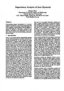
Neither approach considers the representation of abstract classes which are not interfaces. The JSDG represents abstract classes as well as interfaces by treating the interface as a special kind of abstract class. The JSDG deviates from previous interface representations by treating the interface as a special kind of abstract class. Because abstract classes can contain method implementations, the use of callsites to represent abstract methods as proposed by Zhao [20] becomes unsuitable. Abstract methods are represented in the JSDG with method entry vertices. Both Kovács et al. and Zhao omit parameter-out vertices from abstract method declarations [10, 20]. To fully represent a method signature, if a method returns a value (i.e. is not void), the JSDG connects Figure 6: Example of a call to a method in a poly- the method entry vertex to a parameter-out vertex. The interface dependence graph (InDG) conmorphic object (see node S12a in appendix) sists of an interface entry vertex which is connected to a set of method entry vertices representIn every case, an object is expanded to reveal its ing its abstract methods via abstract member edges. data type(s). These are further expanded to repreThe method entry vertices are connected to paramsent their respective data members. If a data member eter vertices, which represent their input paramehappens to be another object, this must further be ters6 . Each method entry vertex is connected to the expanded to reveal its type(s) etc. This can become method entry vertex of the method implementing it problematic if the object is defined recursively. To by an implement abstract method edge. If a class address this issue, Liang and Harrold employ kimplements an interface, the class is connected to limiting (the tree is only expanded to a level k) [12]. the interface by an implements edge. If a class C1 extends class C2, and C2 implements an interface, 2.5 Interface Dependence Graph C1 will automatically implement that interface as well. C1 does not to be connected to the interface by an implemented edge, as this is implicit in the inheritance hierarchy. Figure 7 illustrates the Calculator InDG, which is connected to the SimpleCalc class. The multiply(int c, int d) vertex has been expanded to reveal its formal vertices in order to illustrate how parameters from the interface are connected to their implementation counterparts. e.multiply(6,20)
e
SimpleCalc.multiply
6
AdvancedCalc.multiply
20
20
6
Interface Calculator
public int average()
public int multiply(int c, int d)
int c
int d
int
SimpleCalc implements Calculator public SimpleCalc()
int getB()
public SimpleCalc(int a, int b)
public int average()
private int add(int c, int d)
int getA()
public int multiply(int c, int d)
Abstract Classes An abstract method contains only the method signature and leaves its implementation to a subclass. If a class contains an abstract method, it must itself be declared abstract. Abstract classes cannot be instantiated. In C++ the equivalent effect is achieved by including a pure virtual method7 in the class. Because interfaces are themselves abstract, abstract classes are represented in a similar fashion. The interface entry vertex is replaced with a class entry vertex. The class entry vertex is connected to abstract methods via an
private int divide(int c) c=c_in
d=d_in
result_out=result
Figure 7: The InDG (see node IE43 in appendix) The Java interface has been represented by both Kovács et al. and Zhao [10, 20]. Its role is to specify the signatures of the methods which must be implemented by any object implementing the interface. 6 These 7A
vertices do not need to be tagged to assign an input value to a temporary location, because the interface is abstract pure virtual method is a method that is declared as virtual and does not include a method body, but is initialised as ‘0’.
5
3 CONSTRUCTING THE GRAPH
2.6 Package Dependence Graph
abstract member edge. Abstract methods are connected to their implementations via implement abstract method edges, as they would be in an interface. Non-abstract methods are represented as they would be in a normal ClDG. If a class entry vertex has at least one abstract member edge, it is an abstract class.
Represent single inheritance (class hierarchy) [10]
The JSDG pools together the benefits of several previous dependence graph approaches. It provides a new representation for interfaces and abstract classes and combines the single-inheritance representation presented by Kovács et al. with the Absence of Virtual Methods In C++, the inheri- representation for methods, classes and packages proposed by Kovács et al. and Zhao [10, 20]. It tance structure is slightly more complicated than in also represents individual objects and can distinJava. Methods which can be overridden and dynamguish data members in parameter objects [12]. The ically bound at run-time must be explicitly marked pre-processing stage is beyond the scope of this docas ‘virtual’. In Java, it is simply presumed that any derived class which contains a method with the ument, but some important features are discussed same signature as a method in a superclass overrides briefly. The graph construction proceeds as follows: all definitions further up the inheritance hierarchy. 1. Construct MDGs Because Liang and Harrold base their dependence graph on C++, they require a more complex inheri(a) Pre process each method to ascertain tance structure [12]. Because Java allows only sincallsites gle inheritance and does not feature virtual methods, (b) Expand objects the JSDG can adopt a simpler inheritance structure, where derived classes can simply reuse base-class (c) Build data dependencies for data memmethod definitions [10] (its simplicity is illustrated bers in figure 2). (d) Connect MDG nodes to a class node
2.6 Package Dependence Graph
2. Construct ClDG
A package defines a collection of classes which are conceptually similar or are dedicated to a similar purpose. It is represented by a package dependence graph (PaDG) [10, 20]. Packages are important in terms of slicing, because they are needed to accurately compute variable visibility. A package entry vertex represents the package, which is connected to each class and interface entry vertex belonging to the package via a package member edge.
3. Construct InDG 4. Construct PaDG
Pre-processing the Java program Building the JSDG requires prior control and data flow analysis. As discussed in section 2.1, this stage is instrumental in ensuring that the resulting JSDG and any operations on it are as accurate as possible. Chambers et al. propose an approach for accurately analysing data dependencies in Java programs which can han3 Constructing the Graph dle exceptions, synchronization and memory consistency [3]. Tonella et al. propose a context Ultimately, a Java System Dependence Graph and flow-insensitive Points-To Analysis (PTA) ap(JSDG) must satisfy the following properties: It proach, which can reduce the size of the initial graph must to increase the accuracy of operations such as slicing [18]. Grove et al. propose an approach to elicit Represent methods, classes, and packages call-graphs for OO programs [5]. [10, 20] A practical approach to carry out this prior analRepresent abstract methods / classes and in- ysis would be to use the Soot analysis framework, which provides several packages to analyse the Java terfaces byte-code. A problem with using Soot for this purRepresent individual objects (it must be able pose is that it operates on the Java byte-code, not the to correctly represent polymorphic parame- source code. One line of source code usually conters calls to polymorphic objects) [12] stitutes several individual byte-code instructions8. 8 Byte-code
instructions are mapped to their respective source code line numbers in the LineNumberTable attribute of a class.
6
3 CONSTRUCTING THE GRAPH
This is made more difficult by the fact that if a class file is to be used in Soot, it has to be converted into one of several intermediate Soot formats (i.e. Baf, Jimple or Grimp), further confusing the mapping between intermediate instructions and source code line numbers. The upside of analysing a program at a byte-code level is that more precise results can be produced, especially in the case of slicing, where it is usually desirable to obtain a slice which is as accurate as possible.
ject. This subgraph is traversed, and each vertex v is expanded as discussed in section 2.4.1. In the getStats(SimpleCalc e) method given in figure 8, the vertices e, e.getA() and e.getB() belong to the object-flow subgraph and hence are expanded. [Note that it is necessary to expand the System.out.println... statement, because it is composed of two method calls, which must be represented separately.] public void getStats(SimpleCalc e)
1. Construct MDGs e
1. (a) Processing Callsites In order to determine how the methods communicate with each other, each method must be processed individually. Methods to be processed are identified by traversing the call graph. Once a callsite has been identified it can be expanded (ref. 2.4.1). Once this is done, the call dependence edge is followed to determine the called method, where the appropriate formal-in and formal-out vertices are connected to its entry vertex. Conforming to Liang and Harrold’s approach, we only add parameter vertices for parameters and global variables in the callee’s GREF and GMOD9 . A data dependence exists between vertices A and B if A modifies / defines a variable which is referenced / used by B. To compute the data dependencies introduced by an object’s data members, Liang and Harrold only associate the use of an object with a callsite if the called method is not a construction. An object definition is associated with a call vertex if the called method is not a destruction. In Java, destructors do not exist. In C++, every object is destroyed when it goes out of scope or a pointer variable is deleted. In Java, unused objects are automatically destroyed in order to free up memory by way of a garbage collector. Java’s closest equivalent of the destructor is the finalize() method10. Hence, an object definition is associated with a call vertex if it is not a finalize() method.
System.out.println("a: "+e.getA()+"b: "+e.getB())
e.getA()
e.getB()
Figure 8: Example of an object-flow subgraph (vertices belonging to the graph are in bold) 1.(c) Build Data Dependencies for Data Members Once object vertices have been expanded, data dependencies must be established for the individual object data members. For a callsite c in a subgraph, the definition set DEF(c) of data members consists of c’s actual-out vertices. The use set USE(c) is consists of c’s actual-in vertices. If the call statement carries a parameter object, the object’s data members must be added to the DEF and USE sets. For a parameter object, if the vertex defines the object11 , the object’s data members are added to the DEF set. Similarly, if the vertex uses the object, the data members are added to the USE set. Having computed the DEF and USE sets, it is possible to generate the def-use chains as data dependencies. 2. Construct ClDG It is assumed that the class hierarchy is calculated as part of the pre-processing stage. For every class, a class entry vertex is generated, which is connected to the method entry vertices of methods belonging to that class via class membership edges. Kovács et al. use this connection to determine the visibility of the method within the class [10]. We adopt this approach as well, so that every class membership edge is tagged as either
1.(b) Expand Objects In order to expand objects, Liang and Harrold introduce the notion of an object-flow subgraph. This is a subgraph in the data dependence graph of a method, containing only the vertices that reference a given ob-
9 GMOD(m) is the set of non-local variables which can be modified within a method m and GREF(m) is the set of non-local variables which can be referenced [1]. 10 In C++, objects are explicitly destroyed as soon as they are out of scope. In Java, they are marked as unused when there are no longer any non-garbage references pointing to them. There is no way of guaranteeing when the garbage collector runs and when the finalize() is run. The timing of the garbage collection is also implementation-dependent, i.e. when the finalize() method is run depends in part on the Java implementation being used. 11 An example of this would be i.compareTo(new Integer(5)); where i is of type Integer
7
4 OPERATING ON THE JSDG
tor is forced to jump from one part of the code to another [4].
public, private, or protected. If a class A extends a class B, A is connected to B via a class dependence edge. By connecting the classes in this manner, Java’s single inheritance structure is emphasised. If a class contains an abstract method (i.e. the class is abstract), it is still represented by a conventional class entry vertex, but is connected to the abstract method via an abstract member edge. The abstract method is connected to its implementation in a subclass via an implement abstract method edge.
4.1 Slicing
If the JSDG is to be sliced, it needs an additional edge called the summary edge. These represent the transitive flow of dependence across a callsite caused by both control and data dependencies. Such an edge connects an actual-in vertex to an actual-out vertex if the value associated with the actual-in ver3. Construct InDG For every interface, there ex- tex may affect the value associated with the actualists an interface entry vertex. This is connected out vertex. Figure 10 shows the same callsite exto method entry vertices representing the abstract ample as figure 1, but adds transitive dependencies methods in the interface. These are each connected from c_in=a to added=result_out and d_in=b to to their set of formal-in vertices. Each method is added=result_out. connected to its respective implementation’s method entry vertex via an implements abstract method edge. The formal-in vertices connected to the interface method entry vertices are connected to their implementation counterparts via parameter-in edges. int added=add(a,b)
private int add(int c, int d)
c=c_in
4. Construct PaDG The PaDG is represented by a package entry vertex, which is connected to its class entry vertices and interface entry vertices via package edges. It is possible for a program to consist of package hierarchies. In this case, subpackages are connected to superpackages via package dependence edges. This is an important feature for multi-package programs, because it enables the accurate calculation of the visibility of classes.
d=d_in
int result = c + d
c_in=a
return result
d_in=b
added=result_out
result_out=result
Figure 9: Example of method call with transitive edges between actual-in and actual-out vertices
The slicing algorithm proposed by Horwitz et al. is split into two phases. The first phase traverses backwards along control, call, parameter in and data dependence edges marking every graph vertex it passes. In the second pass, the algorithm 4 Operating on the JSDG traverses back from each marked vertex along conAlthough this paper focuses on the graph itself, it trol, parameter out and data dependence edges [9]. makes sense to give the reader an idea of some of its Liang and Harrold extended this algorithm to enable potential benefits. The main application is slicing, the slicing of individual objects [12]. An example which has been the focus of the majority of depen- of a slice according to the Horwitz et al. method is dence graph based papers [9, 10, 11, 12, 14, 20]. marked out in appendix C (shaded vertices belong In addition to slicing, Horwitz and Reps also pro- to a slice taken from statement S25). pose that dependence graphs can be used to establish differences between two programs (program differ- 4.2 Program Metrics encing) and to integrate changes carried out on one program into another similar program (program in- Ottenstein and Ottenstein suggested that the depentegration) [8]. The combination of data and control dence graph would be a suitable basis for the caldependencies provides a useful basis for the calcula- culation of program metrics. The JSDG allows indition of program metrics [14]. It would also be inter- vidual methods, classes or packages to be measured. esting to investigate the usefulness of the JSDG with This could be especially useful as a heuristic to softrespect to software inspections. In object-oriented ware restructuring. If the complexity in a given area software inspections, delocalised software artifacts of the program exceeds a certain threshold, it could which are connected by control and data dependen- indicate that a refactoring (or other form of code recies hamper code reviews, because the code inspec- structuring) could be necessary. 8
REFERENCES
4.3 Software Inspections
size can make the generation and storage of such a graph an expensive process. Depending on the purpose for which it is intended certain edges and vertices can be removed if they are not going to be used (i.e. interface related vertices and edges can be removed if the graph is only needed for slicing operations). If we are only interested in a given subset of methods in the program other parts could be sliced away.
It would be interesting to expand on Weiser’s original investigations into slicing based metrics [19]. Bieman and Ott propose the use of program slices to measure functional cohesion [2]. According to Riel, a good object-oriented designer strives for “tight cohesion within classes and loose coupling between classes” [15]. It would be useful to extend this measure to the object-oriented paradigm. The JSDG provides the basic representation for the computation of these slices.
5 Conclusions
4.3 Software Inspections
This dependence graph provides a useful basis for the representation of Java programs. It enables several useful software engineering operations to be carried out as queries / manipulations on the graph, which offers greater speed and precision than conventional methods (Horwitz et al. illustrate the increase in precision when slicing the SDG as opposed to Weiser’s conventional algorithm [9]). It provides a representation for interfaces and abstract classes and enables objects and object data members to be treated individually in any operation (e.g. the program can be sliced object by object). Now, it is possible to re-interpret the dependence graph applications as suggested by Ottenstein and Ottenstein and Horwitz et al. in terms of the OO paradigm. Several potential research areas concerning the JSDG have been proposed. The next logical step in making the JSDG a practical software engineering tool is to develop a tool which will automatically build an internal representation of a given Java program.
Dunsmore et al. state that delocalised software artifacts hamper object oriented code inspections [4]. Software artifacts become delocalised because object-oriented paradigm features such as inheritance, polymorphism and dynamic binding can cause code which is responsible for the execution of a single task to be dispersed throughout the program. These dispersed artifacts are all connected via some form of dependence (or chain of dependencies), which can be traced on the JSDG. Slicing could be used to statically determine possible paths of execution in the program, providing the inspector with a reading strategy for the inspection. “Program understanding requires tracing chains of method invocations up and down the class hierarchy” [4]. The inspector must be able to abstract the high level function of a software module to verify that it conforms to its specification. Harman et al. propose a framework for combining slicing and concept assignment [6], which would significantly reduce this laborious aspect of inspections. Further research is required if this approach is to be made practical for object-oriented systems. The JSDG provides a useful basis for investigating the feasibility of extracting Executable Concept Slices (ECSs) for object-oriented programs.
References [1] J. Banning. An efficient way to find the side effects of procedure calls and the aliases of variables. In Conference Record of the Sixth Annual ACM Symposium on Principles of Programming Languages, pages 29–41, January 1979. [2] J. Bieman and L. Ott. Measuring functional cohesion. IEEE Transactions on Software Engineering, 20(8):644–658, August 1994.
4.4 Practical Issues The graph has not been designed to incorporate exceptions and threads. Sinha et al. represent exceptions by adding vertices and edges around the try and catch clauses of an exception[17]. Hatcliff et al. study the slicing of multi-threaded programs, but do not specifically relate their solution to a program dependence graph representation [7]. Another problem that is prevalent amongst most static analysis techniques is that the graph produced is very substantial. This is due to the fact that a static approach must lay out every possible execution that could possibly be carried out by the program. The
[3] C. Chambers, I. Pechtchanski, V. Sarkar, M. Serrano, and H. Srinivasan. Dependence analysis for java. In Workshop on Compilers for Parallel Computing, La Jolla, LA, August 1999. [4] A. Dunsmore, M. Roper, and M. Wood. Object-oriented inspection in the face of delocalisation. In Proceedings of the 22nd International Conference on Software Engineering, Limerick, 2000. [5] D. Grove, G. DeFouw, J. Dean, and C. Chambers. Call graph construction in object-oriented languages. In OOPSLA ’97 Conference Proceedings, 1997. [6] M. Harman, N. Gold, R. Hierons, and D. Binkley. Code extraction algorithms which unify slicing and concept as-
9
A LEGEND
signment. In 9th IEEE Conference on Reverse Engineering (WCRE ’02), Richmond, Virginia, USA, 2002.
ings of the ACM SIGSOFT/SIGPLAN Software Engineering Symposium on Practical Software Development Environments, pages 177–184, 1984.
[7] J. Hatcliff, J. Corbett, M. Dwyer, S. Sokolowski, and H. Zheng. A formal study of slicing for multi-threaded programs with jvm concurrency primitives. Technical Report 99-6, Kansas State University, March 1999.
[15] A. Riel. Object-Oriented Design Heuristics. Addison Wesley, 1996. [16] M. Shaw. Pattern Languages of Program Design 2, chapter Some Patterns for Software Architectures. Addison Wesley, 1996.
[8] S. Horwitz and T. Reps. The use of program dependence graphs in software engineering. In Proceedings of the 14th International Conference on Software Engineering, 1992.
[17] S. Sinha, M. Harrold, and G. Rothermel. Systemdependence-graph-based slicing of programs with arbitrary interprocedural control flow. In Proceedings of the 21st International Conference on Software Engineering, May 1999.
[9] S. Horwitz, T. Reps, and D. Binkley. Interprocedural slicing using dependence graphs. ACM Transactions on Programming Languages and Systems, 12(1):26–60, January 1990. [10] G. Kovacs, F. Magyar, and T. Gyimothy. Static slicing of java programs. Technical Report TR-96-108, Research Group on Artificial Intelligence, Hungarian Academy of Sciences, Joesf Attila University, 1996.
[18] P. Tonella, G. Antoniol, R. Fuitem, and E. Merlo. Flow insensitive C++ pointers and polymorphism analysis and its application to slicing. 19th International Conference on Software Engineering, pages 433–443, May 1997.
[11] L. Larsen and M. Harrold. Slicing object oriented software. In 18th International Conference on Software Engineering, pages 495–505, March 1996.
[19] M. Weiser. Program slicing. In Proc. 5th Int. Conference on Software Engineering, pages 439–449, New York, 1981. IEEE.
[12] D. Liang and M. Harrold. Slicing objects using system dependence graphs. International Conference on Software Maintenance, pages 358–367, November 1998.
[20] J. Zhao. Applying program dependence analysis to java software. In Proc. Workshop on Software Engineering and Database Systems, pages 162–169, Taiwan, December 1998.
[13] P. Livadas and S. Croll. Program slicing. 1992. [14] K. Ottenstein and L. Ottenstein. The program dependence graph in a software development environment. In Proceed-
A
Legend class / interface entry vertex
method entry vertex / statement vertex / formal or actual parameter in/out vertex
control dependence belongs to (can be tagged to denote the visibility of a method) OR interface member edge implements edge data dependence edge call / implements abstract method edge Data member
10
CE1
public class Execute{ public static void main(String args[]){ SimpleCalc e;
E2 S3
if(args.length > 0){
CE17
public class SimpleCalc implements Calculator{
S18 E19
int a,b; public SimpleCalc(){
S20
a = 6;
C5 C6
int a = Integer.parseInt(args[0]); int b = Integer.parseInt(args[1]);
S21
b = 20;
C7
e = new SimpleCalc(a, b); }
E22 S23
else
C24
S4
int average(); int multiply(int c, int d); }
}
CE46 E47 S48
} public int average(){
interface Calculator{
E44 E45
public SimpleCalc(int aIn, int bIn){ a = aIn; b = multiply(a, bIn);
{
IE43
public class AdvancedCalc extends SimpleCalc{ public AdvancedCalc(){ a = 6;
S49
b = 20; } public AdvancedCalc(int aIn, int bIn){
C8
e = new AdvancedCalc();
E25
C9
computePower(e);
C26
int added = add(a,b);
S51
a = aIn;
C27 S28
int divided = divide(added); return divided;
C52
b = multiply(a, bIn);
11
S10
} System.out.println(e.average());
C11 S12
getStats(e); System.out.println(e.multiply(6,20));
E13 S14 E15 S16
} private int add(int c, int d){
E29
}
S30
int result = c+d;
public void getStats(SimpleCalc e){ System.out.println(“a: “+ e.getA() + “ b: “ + e.getB());
S31
return result;
}
E32
public void computePower(AdvancedCalc e){ System.out.println(e.power());
S33 S34
} private int divide(int c){ int result = c/2; return result;
}
}
} protected int multiply(int c, int d){
E35 S36
for(int i=0; i