custom software that could instead have been developed once and used by all the ... extends the functionality of the chosen SCADA toolkit, but it can also benefit ...
10th ICALEPCS Int. Conf. on Accelerator & Large Expt. Physics Control Systems. Geneva, 10 - 14 Oct 2005, WE2.1-6O (2005)
THE JCOP FRAMEWORK Oliver Holme, Manuel Gonzalez Berges, Piotr Golonka, Sascha Schmeling CERN, Geneva, Switzerland ABSTRACT In order to reduce duplication, and hence reduce the overall manpower required for the development of the LHC experiment control systems, the Joint Controls Project (JCOP) was setup as a collaboration between CERN and the LHC experiments. The aim of JCOP is to provide common controls solutions for the four experiments. One deliverable of JCOP has been the selection of a number of standard technologies to be used for these systems. These include a Finite State Machine (FSM) toolkit, three communications protocols – OPC (OLE for Process Control), DIP and DIM (CERN developed protocols) – standard PLCs (Siemens and Schneider), standard field buses (CANBus, WorldFIP, ProfiBus) and PVSS (Prozeßvisualisierungs- und Steuerungssystem) for the supervisory level. The SCADA (Supervisory Control And Data Acquisition) system PVSS is a highly sophisticated product and offers a lot of flexibility. As a result of this flexibility there are often several ways to implement something and this can make the product complex to use for an occasional user. Similarly, some of the other products, e.g. the FSM toolkit, are also potentially complex to use. Therefore, it was decided to create a layer on top of PVSS and the other tools to simplify their use for the application developer and also to provide customized components that can be used directly in an experiment control system. This activity, which is a major activity within JCOP, is the so-called JCOP Framework (FW) development. The JCOP Framework is an integrated and coherent set of guidelines, devices and tools that are required in common by the four experiments. This paper discusses the overall architecture of the FW as well as the associated deliverables. In particular, it will highlight the component nature of the FW and provide an overview of those which are provided. It will then go on to describe a number of these components in more detail and then finish by discussing the advantages of this approach as seen from the application developer’s point of view, in particular in highlighting the reduced development time. INTRODUCTION The LHC experiments’ control systems are being developed by hundreds of different developers, distributed widely around the world. This leads to autonomous teams developing solutions which at some point have to be drawn together to form the final experiment control system. The complexity of integrating all these different developments could be very time consuming if measures are not taken to guide the work of the development teams. JCOP [1] was established as a collaboration between CERN and the LHC experiments to identify common needs and provide common tools and solutions that the four experiments can use as a basis for the development of their final control systems. JCOP has identified a number of standard technologies that shall be used, including several industry standards and products. The chosen technologies include communication protocols, PLCs, field buses and a SCADA system. THE SCADA SYSTEM The SCADA system selected by JCOP is PVSS II [2]. This is a sophisticated industrial SCADA toolkit which is developed by the Austrian company, ETM. By agreeing on a standard SCADA system to be used in all controls development for the LHC experiments, the task of the experiments to integrate the separate developments is already significantly reduced. One reason that JCOP chose PVSS is that it offered excellent flexibility and few constraints on the development of final applications [3]. This flexibility ensures that CERN will be able to make solutions that meet its needs, but it also raises potential difficulties with integration. With developers being able to use PVSS in a variety of very different ways, it would still be possible to end up in a position where it was extremely difficult to incorporate all the diverse developments into a single experiment control system. Also, such an open development environment can be complex and intimidating for occasional users. To avoid these potential problems, it was decided by JCOP to produce a collection of homogeneous tools and a set of guidelines to be used by all developers of controls systems. This collection of tools and guidelines combines to form the JCOP Framework (FW) [4].
10th ICALEPCS 2005; O.Holme,M.Gonzalez-Berges,P.Golonka,S.Schmeling et al. : The JCOP Framework
2 of 6
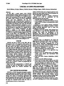
THE JCOP FRAMEWORK The main motivation for the development of the FW is to reduce the effort needed by developers of the experiment control systems. As discussed earlier, by providing guidelines to developers – including standard look and feel, naming conventions, etc. – the task of integrating the many different developments will be simplified. Also, the FW provides common functionality that is required in a high energy physics (HEP) environment – in particular the LHC experiments. By providing this in the FW, experiment control system developers can immediately use a tested piece of software and do not have to develop the whole solution themselves. Any development in the FW is available to all experiments, which means that common features can be developed once for the FW and reused many times within each of the experiments. This helps to avoid that experiments spend time to develop custom software that could instead have been developed once and used by all the experiments. The FW also integrates other tools that are not included with PVSS. One example of this is the controls hierarchy which models the experiment using finite state machines (FSMs). The FSM toolkit [5] is based on SMI++ and is a stand-alone product which can be used independently of a SCADA tool. However, the FW incorporates this toolkit and provides a consistent programming and graphical user interface for control system developers. Other components that have been integrated include communication toolkits for protocols which are not supported by PVSS, for example the CERN developed DIP [6] and DIM [7] protocols. This approach means that the FW not only simplifies and extends the functionality of the chosen SCADA toolkit, but it can also benefit from other stand-alone developments and provide a simple way for control system developers to access this functionality. As mentioned, the FW helps to provide a homogeneous layer combining all the benefits of the SCADA toolkit and other toolkits. In addition, the FW adds to the functionality of the toolkits and provides a higher level of abstraction that reduces the need for people to have expert knowledge of the individual products. This way, developers benefit from the high-level HEP-specific developments in the FW, but still have access to the original toolkits if they need to develop some specific features not provided for in the FW. This is highlighted in Figure 1 which indicates where the FW fits into a typical supervisory control system development. Experiment Control System JCOP Framework SCADA Toolkit (PVSS)
Other Toolkits (e.g. FSM, DIM, DIP)
PC (Windows, Linux)
Recommended communication protocols (e.g. OPC, DIM) Hardware
DIP communication External Systems
Figure 1 – The JCOP FW in the context of a typical experiment control system It was found that amongst the requirements of the four LHC experiments, there were common facilities that were required by everybody. There were also requirements from some experiments that were not needed by others. To accommodate all these requirements in the FW it was decided to split the FW into a series of components. Each individual component can be installed as required. If a particular component is not useful for a certain development, then this component can simply not be installed. This allows the flexibility to meet the needs of each of the users of the FW. They have access to all the functionality they need, but can easily ignore the parts that are not useful to them.
10th ICALEPCS 2005; O.Holme,M.Gonzalez-Berges,P.Golonka,S.Schmeling et al. : The JCOP Framework
3 of 6
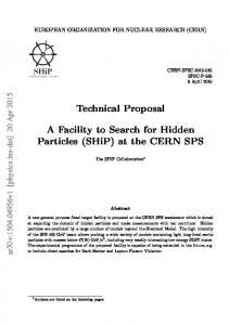
There are three main types of component in the FW: 1. Core – contains fundamental, reusable functionality 2. Tools – used to handle, display and store data (e.g. communication protocols, trending displays, user access control, storage and retrieval of configuration data from a database) 3. Devices – used to monitor and control common hardware devices (e.g. power supplies from Wiener, CAEN and ISEG, analogue and digital inputs) The device components include specific information relating to the hardware that they will control. This information includes a data structure in which the process variables and control parameters are stored and information on the configuration necessary to connect the SCADA tool to the hardware. Additional information is provided about other possible configuration including alarms on some values. All this configuration information combines to form, in FW terminology, the device definition. A typical FW component includes some libraries of code, a set of graphical user interface (GUI) panels, some configuration data and, if it relates to a hardware device, the device definition is included as well. The configuration data can be used very flexibly. For a simple example, it could consist of the settings needed by the SCADA toolkit to use the component correctly. Figure 2 shows a graphical representation of a typical FW component.
Typical FW Component
Config data
Device definition
Code libraries
GUI panels
Figure 2 – The contents of a typical FW component The components can be installed and removed using the FW Installation Tool. This tool automatically installs the necessary files and can perform complex actions during the installation to configure correctly the target system or to perform migration tasks when installing a newer version of a component. FW Core The core of the FW provides basic functions that are not provided as part of PVSS, but are of general use to all development for the LHC experiment control systems. This is the only component that is required to be installed. The features it provides include: • Hierarchical organization of devices • Controls hierarchy using FSM modelling • Configuring of devices – e.g. setting up connection to hardware, alarms • Infrastructure for easily creating and configuring new devices • Creation and configuring of multiple devices in one action The functionality provided by the Core is reused in the other FW components. This aids the development of FW components, because many of the fundamental features are already implemented and can be reused. Likewise, developers of the experiment control systems can benefit by reusing the Core. In addition, they can also look at the other FW components as examples to see how the Core has been used in other contexts. This allows the control system developers to learn by example which can increase the speed at which they become familiar with all that the FW and PVSS can accomplish.
10th ICALEPCS 2005; O.Holme,M.Gonzalez-Berges,P.Golonka,S.Schmeling et al. : The JCOP Framework
4 of 6
BENEFITS OF USING THE FW To understand the benefit of using the FW, an example will be used of creating and configuring a high voltage power supply. The high voltage devices in the example will be CAEN systems which are widely used in the HEP community. A FW component is available to facilitate the creating, configuring and control of the CAEN devices in the control system. The effort of using just PVSS to control these devices will be compared with the effort when using PVSS combined with the FW. Typically the creation of a CAEN high voltage power supply involves instantiating a crate device, at least one board and at least one channel in each board. These device instances are basically data structures that match the data which is provided by the real hardware. Each device instance needs to be configured with alarms and the necessary settings so that they can communicate with the real hardware. The recommended communication standard used for controlling CAEN crates is OPC. As mentioned earlier, with the FW, the information of what needs to be configured is stored in the device definition which is installed when you install the FW CAEN component. When using PVSS without the FW, there is no such help and the software developer will have to have an expert knowledge of CAEN devices, the OPC server name space and how to configure PVSS to communicate correctly. So already, before creating anything, the FW has reduced the prerequisite knowledge to perform this setup. Creating Devices One motive for selecting PVSS instead of other competing SCADA products was the fact that it supported a structured name-space [3], where one structure definition could be used to represent a single type of hardware. A user who is not using the FW would have to create a device structure to represent the CAEN devices, probably involving several design iterations to select the best structure. This would necessarily involve a detailed understanding of the hardware and what values were required to be read and controlled. In addition, different developers using the same hardware would be very likely to design different data structures and this would cause incompatibility between developments that would cause severe problems during the system integration phase. A developer using the FW automatically has the standard structure installed ready for them to use. Once the data structure exists, creating an instance of this structure is simple using PVSS. New instances can be created with a single line of code or with around three user interface interactions using the graphical tools provided by PVSS. The FW does not attempt to improve on this area where users can already benefit from the built-in functionality of PVSS. When creating large numbers of devices, especially when the hardware implies a certain hierarchy (e.g. CAEN crates contain boards, which in turn contain channels), it is useful to recreate this hierarchy at the supervision level. Suppose a crate contains 16 boards, each with 12 channels, then this results in 192 channels. If these were presented in a flat structure, it could be very difficult to find the 6th channel in the 4th board for example. While PVSS provides structuring of data to represent a device, this same method is not recommended to support the structuring of devices in hierarchies. So the FW implements this requirement of organizing devices in hierarchies. Without the FW, a developer would have no hierarchy toolkit and might create their own novel solution. By using the FW, the developer can be confident that they are using a standard and supported hierarchy which will be compatible with other developments based on the FW. Configuring Devices Once the device instances have been created, it is necessary to configure each instance. This typically involves establishing a connection to the real hardware and setting alarm limits for certain values. For each item in the device instance structure, a hardware connection configuration and alarm configuration must be created if necessary. As an example, a CAEN crate (excluding any boards and channels) requires 20 hardware connections to be configured and has five readings which have alarms. Setting up an alarm in PVSS can be done either with code or via a graphical interface. To configure a simple alert on a digital input requires approximately 10 configuration attributes to be set. More
10th ICALEPCS 2005; O.Holme,M.Gonzalez-Berges,P.Golonka,S.Schmeling et al. : The JCOP Framework
5 of 6
complex alerts for analogue values can involve up to 40 attributes needing to be set per analogue value. Using the standard PVSS graphical tools, this is simple but this approach is not practical for large numbers of instances, especially when the configuration needs to be automated. To set an alert using PVSS scripting requires at least as many lines of code as there are attributes to set, but it also requires a detailed knowledge of setting alerts in PVSS and how to use the PVSS scripting language to achieve this. The same applies for configuring hardware connections (around 10 attributes to set per value) where prior knowledge of both PVSS and the communication protocol are required. In contrast, the FW provides one function which can set up the alarm and one to set the hardware connection. These functions take all the required parameters and set the necessary attributes. This hides the complexity of the code which actually sets the attributes and removes the need of the user to understand which attributes need to be set in which order. This higher level of abstraction means that users of the FW can concentrate on configuring the devices they require without having to become expert users of PVSS to do so. Advanced Device Operations So far the simple case of creating and configuring single devices has been mentioned. While it has been shown the FW greatly simplifies these tasks, the real power of the FW is appreciated when creating large numbers of devices in one operation. Assuming that the CAEN crate from the earlier example is created and fully configured, the next probable step of a user would be to add a board and the channels of that board. Supposing that the board has 12 channels, a total of 13 devices need to be created (12 channels and 1 board). On these devices there are a total of around 60 alerts to be defined and at least 250 hardware connections to be set up. This means there are literally thousands of configuration attributes that need to be set. Of course, a control system developer could create code that performs the necessary set up, but in this situation the FW really saves a considerable amount of effort. When automatically creating large numbers of devices in hierarchies, it is necessary to use a default naming scheme for the devices to avoid the user having to enter the names required for each device. This naming scheme is stored in the CAEN FW component in the device definition. Users of the FW benefit from the device definitions, the hierarchical structuring of devices and the functions provided for setting alarm and hardware connections. The FW itself can also use these features to build sophisticated tools that provide the capability for browsing hierarchies of devices in a graphical way and for creating hierarchies of devices. For example, to create the high voltage board with 12 channels, it is possible to load the FW hierarchy editing tool and with 10 mouse clicks the user can initiate the action to create and configure all 13 devices. In this case, the FW hides almost all the complexity of the operation and the user does not need to have any knowledge of the CAEN device internals, the communication protocol or how to configure devices using PVSS. All that is needed is some familiarity with PVSS and the FW to load the graphical hierarchy tool to perform the necessary actions. EXTENDING THE FRAMEWORK It has been demonstrated how the FW eases the work of the control system developer when working with devices for which there is a FW component available. There are some types of hardware that are not used commonly in the LHC experiments and in this case, no FW component will exist. In order to benefit from all the advantages described earlier, it is necessary for a control systems developer to develop their own component for the device. As mentioned earlier, the sophisticated functionality for creating and configuring CAEN devices is derived from the FW Core and the FW CAEN component. The functionality of the Core is available to any component developer, so the hierarchical organization of devices and the methods for creating and configuring many devices are all accessible. The only things that need to be done to access these Core features are: 1. Design the device data structure for the new hardware device 2. Created the device definition which the Core can use to configure the new device 3. Specify the possible hierarchy formations, i.e. which device types can be contained within other device types in the hierarchy 4. Specify the default naming convention to be used when automatically creating devices.
10th ICALEPCS 2005; O.Holme,M.Gonzalez-Berges,P.Golonka,S.Schmeling et al. : The JCOP Framework
6 of 6
By defining these four things, the component developer gains all the benefits explained earlier when creating and configuring devices. The FW Core contains all the GUI panels needed to create the new devices, but it would be necessary to create some new panels for monitoring and controlling the new hardware. Once this is done, the developer could package and distribute the new component to other developers who are using the same hardware. This component would be the same as any other FW component, except that it would be developed, maintained and distributed by somebody outside the JCOP FW development team. Users could install it using the FW installation tool and quickly start to build a control system with this new hardware device. EFFECT ON DEVELOPMENT EFFORT The FW helps to reduce the development effort of the control system developer in many ways: • Homogeneous interface to SCADA and other toolkits • Higher level of abstraction requires less detailed knowledge of toolkits • Extensive HEP-centred functionality provided by FW Core • New developments can reuse any other FW components, particularly the Core • Development guidelines to focus development and maintain compatibility with other systems Earlier it was shown how following the FW philosophy to add a new type of device, a developer can inherit much of the FW functionality and rapidly create a working system for controlling a specific new type of hardware. The effort required to create the same functionality using the SCADA toolkit alone would be considerably greater. The developer would either have to create and configure everything manually, or create a custom mechanism for automatically doing this. Both of these approaches would require considerable time to learn the details of the SCADA toolkit and then more time to create a working system. Around 40 sub-detectors in the four LHC experiments use the JCOP FW, so already the CERNwide development effort for the control systems has been reduced. The FW is developed by one team and reused by many, rather than the same features being developed forty times (at least once by each sub-detector team). In addition, the FW has proved flexible enough, particularly due to the component based nature, to be reused in other applications at CERN. This further reinforces the savings in development time by using the approach of a single FW that can be reused by many users. CONCLUSIONS The JCOP FW provides a unified toolkit for experiment control system developers. In addition, it also contains a set of guidelines which helps to keep distinct developments compatible with one another. Using the FW and following the guidelines ensures that the task of integrating all the systems together into the final experiment control system is simplified. The FW has been shown to be a valid approach as it reduces the prerequisite knowledge needed to start developing and, by providing an extensive HEP focused toolkit, it substantially reduces the development effort to create functional control systems. From a CERN-wide perspective, the reusable nature of the FW has meant that the development effort invested in the FW has been rewarded many times over, as more and more users benefit from its features. See [8] and [9] for other CERN developments that use a similar philosophy. REFERENCES [1] Joint Controls Project, CERN, http://cern.ch/itco/Projects-Services/JCOP/welcome.html [2] PVSS II SCADA Product, ETM, http://www.pvss.com [3] P. C. Burkimsher, “JCOP Experience with a Commercial SCADA Product, PVSS”, ICALEPCS 2003, Gyeongju, Korea, October 13-17, 2003 [4] JCOP Framework Project, CERN, http://cern.ch/itcobe/Projects/Framework/welcome.html [5] C. Gaspar & B. Franek, “Tools for the Automation of Large Distributed Control Systems”, 14th IEEE Real Time Conference, Stockholm, Sweden, June 4-10, 2005 [6] DIP Communications Package, CERN, http://cern.ch/itcofe/Services/DIP/ [7] DIM Communications Package, CERN, http://cern.ch/dim/ [8] M. Gonzalez-Berges et al., “Frameworking: A collaborative approach to control systems development”, ICALEPCS 2005, Geneva, Switzerland, October 10-14, 2005 [9] G. Thomas et al., “LHC GCS: A framework for the production of 23 homogeneous control systems”, ICALEPCS 2005, Geneva, Switzerland, October 10-14, 2005