Close coupling of a MIMD system to a MAXbus pipeline – the Kiwivision MTM multi-transputer architecture Roger S. Clist and Robert J. Valkenburg Machine Vision Team, Industrial Research Limited P O Box 2225, Auckland, New Zealand E-mail:
[email protected] Fax: +64 9 302-8106
ABSTRACT This paper describes the Kiwivision Multi-Transputer Module which has been developed at Industrial Research Limited. It is a MIMD architecture which is tightly coupled to external hardware compatible with the MAXbus™ pipeline standard. The features of Kiwivision are described with particular emphasis given to its inter-processor connectivity and data handling abilities. An implementation of the 2D Fast Fourier Transform is used to illustrate the data movement strengths of the design. Keywords: MIMD, MISD, multi-processor, transputer, pipeline processing
1. INTRODUCTION High-speed machine vision systems frequently need to be capable of performing a wide variety of algorithms, from low-level pixel based operations such as convolution to higher-level functions such as object recognition. To achieve such a diverse range of functions places conflicting requirements on the system architecture. Two architectures frequently used are MISD (Multiple-Instruction–Single-Data) or MIMD (Multiple-Instruction–Multiple-Data). MISD architectures are characterised by multiple operators acting on a single data stream. They are usually referred to as pipelines because the data stream is piped or cascaded through successive processing modules. Pipelined architectures are well suited to the serial nature of raster scanned image data and can perform many pixel and neighbourhood based operations at video rates. However, they are not so well suited to performing higher-level or data-dependent operations which are also required in most machine vision applications. MIMD architectures are characterised by multiple autonomous processing elements capable of exchanging information. Compared to pipelines, the increased flexibility of MIMD architectures allows them to be applied to a far wider range of problems. However, MIMD systems can seldom match the performance of a pipeline for low-level globally-applied image processing operations. Hybrid systems can be designed which include both MISD and MIMD components and thereby incorporate the advantages of both. Low level, pixel-based operations can be performed in the MISD component with the higher-level operations implemented in the flexible MIMD component. In this way the system provides direct support for the different stages of a vision task. The commercial availability of hybrid systems is somewhat limited and it becomes a problem in systems integration. Although many different MISD pipeline modules are available, the range of tightly-coupled MIMD systems is extremely limited. This gap has led to the design of “Kiwivision”, a multi-transputer network which augments a pipeline with a flexible MIMD component to create a complete hybrid architecture. Section 2 of this paper discusses the philosophy behind the Kiwivision design and describes its internal features and physical implementation. Section 3 discusses the connectivity facilities in detail, and Section 4 describes the software used for its control. Section 5 illustrates its data handling capabilities by using an implementation of the 2D Fast Fourier Transform as a practical example.
Proc. SPIE Machine Vision Applications, Architectures, and Systems Integration III, Boston, 31 October 1994
1
2. KIWIVISION DESIGN In seeking to construct an MISD/MIMD hybrid architecture for high-speed machine vision applications it was readily apparent that the MISD component was well served. The decision was made to use the VME-based MaxVideo range of pipeline modules from Datacube, Inc. as there exists a wide variety of modules for different tasks and they are based on a publicly defined video interconnect standard called the MAXbus1 . This paper is concerned with the MIMD component of the hybrid architecture designed at Industrial Research Limited, known as the Kiwivision Multi-Transputer Module (MTM).
2.1 Design philosophy In the design of any parallel system many strategic decisions must be made. Issues such as the method of interprocessor communication, the granularity of the processors and the method of synchronisation must be addressed. There is no optimal solution for all tasks and for a large part the decisions are dictated by the specific applications intended to run on the architecture. Initially the following specifications for the Kiwivision MTM were imposed as design goals: • communication with the pipeline via the MAXbus standard • efficient interprocessor communication for image processing and machine vision applications • scaleable internally and expandable externally • able to be implemented with electronics technology appropriate for low volume production. Several varied image processing tasks were examined for parallel decomposition in order to determine any common features which would influence the design2 . As a result it was decided that two fundamentally different modes of communication were both required: point-to-point and global. Point-to-point communication is necessary to communicate between processors and can be used for synchronisation and exchange of partial results. It is characterised by flexible connectivity but moderate bandwidth. This need is satisfied in the Kiwivision design by the use of inter-processor links as described in Section 2.2.3. Global communication is required for tasks such as data broadcast and data integration and is characterised by a more rigid connective structure with high bandwidth. The MAXbus pipeline serves this purpose for external communications with the Kiwivision system as described in Section 2.2.2. For internal bulk data transfers between processors, the system employs special memory blocks for each processor which are multi-ported and mapped into the address space of a master processor, or to the MAXbus interface, as described in Section 2.2.1. The transputer was selected as the processor primarily because it already provided on-chip support for point-to-point communication thereby simplifying the design and allowing effort to be concentrated on the design of the global data transfer facilities. Much of the circuitry was implemented using programmable logic cell arrays for ease of development.
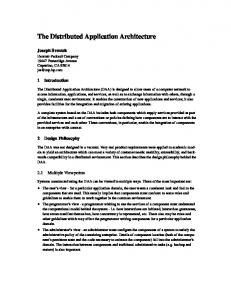
2.2 Kiwivision modules A block diagram of Kiwivision MTM is shown in Fig. 1. This section describes its major internal parts. A complete description of its components is given in the Kiwivision MTM User Reference Manual 3 . 2.2.1 MTM processor modules. The MTM contains up to nine processor modules. Each module is an autonomous unit consisting of an INMOS T805 transputer and 1 megabyte of local memory plus a 512K block of multi-ported memory referred to as an Image/Data Store (IDS). The first module in the system is special—it is called the Transputer Control Module (TCM) and acts as the MTM master controller. Each of the other modules is identical—they are called Transputer Processing Modules (TPM) and may be considered as workers. They provide the basic computational power of the MTM. The processor of each TPM is fully independent and can directly access its local memory and associated IDS only. However, the TCM transputer is more powerful and can access the IDS memories of all MTM transputers either singly or in broadcast modes as described later. This addresses the global data transfer design goal for internal data movement.
Proc. SPIE Machine Vision Applications, Architectures, and Systems Integration III, Boston, 31 October 1994
2
Video bus
MAXbus Interface
IDS0
Dual-Port RAM
TCM
Transputer Control Module
IDS1
IDS2
...
IDS8
Image/Data Stores
TPM1
TPM2
...
TPM8
Transputer Processing Modules
Transputer links
Interrupts
Configuration link
CrossPoint Switch
VMEbus Interface link
32 links
Link Interface
VMEbus Interface
Fig. 1. Kiwivision MTM block diagram
2.2.2 MAXbus interface. The TCM/TPM modules send and receive data to/from the pipeline via the MTM MAXbus Interface. This is a programmable region-of-interest interface enabling reception or transmission of data frames of variable size at video rates. Under the control of the TCM master transputer, data can be received from the pipeline into any IDS memory, or into multiple IDS memories simultaneously. Likewise data can be transmitted to the pipeline from any IDS memory as selected by the TCM transputer. This addresses the global data transfer design goal for external data exchanges. 2.2.3 Link interface. Each processor in the MTM, by virtue of it being a transputer, is endowed with four high-speed serial communication links. The MTM also contains a 32-link cross-point switch which is controlled by the TCM transputer. All links in the MTM are brought out to the front panel (collectively referred to as the Link Interface). This facility addresses the point-to-point inter-processor communication design goal. 2.2.4 VMEbus interface. This comprises registers which control three resources: the MTM interrupt structure; a 16K block of dual-ported memory which can be accessed by the VME host and the TCM transputer; and a link adaptor which is accessed by the VME host. The link adaptor is normally connected to the TCM transputer, and used for downloading transputer code from the host to the MTM network. It also provides a line for subsequent communications between the two systems.
2.3 Physical implementation Although shown as a single logical entity in Fig. 1, the MTM physically comprises several 6U format VME circuit boards. These boards are connected together by a backplane which carries the MTM internal signals (MTMbus). The backplane plugs into the VMEbus backplane so that the Kiwivision boards are physically spaced from the VMEbus. The Interface Board contains the VMEbus interface and the MAXbus interface, and occupies the left-most position in the backplane. The Control Board contains the TCM master transputer and occupies the adjacent position. Processor Boards contain the TPM worker transputers and occupy any of the remaining positions.
Proc. SPIE Machine Vision Applications, Architectures, and Systems Integration III, Boston, 31 October 1994
3
VMEbus
CPU or SBUS to VME Adaptor
...
...
Processor Board
Control Board
Interface Board
...
Processor Board
MTMbus
Pipeline Modules
External Transputers Kiwivision MTM
Camera Monitor MAXbus
Link Interface and Cross-Point Switch
Fig. 2. Physical interconnectivity of a Kiwivision system
A minimum Kiwivision configuration with a single transputer consists of an MTM backplane, an Interface board and a Control board. The system is expanded by adding Processor boards. Each additional Processor board adds either one or two worker transputers. A fully configured system with four Processor boards achieves the system maximum of nine transputers each having MAXbus access. Additional transputers can be added to the network if external transputer hardware is used. A conceptual plan view of a complete MISD/MIMD system is shown in Fig. 2. This diagram also portrays the major data communication pathways that are utilised, namely the VMEbus, the MAXbus, the MTMbus, and the Link Interface. The VMEbus supplies power to all boards in the VME system, with a host CPU or workstation adaptor being used for overall control. The pipeline modules are used to implement the MISD functions to acquire, store, process, and display either whole images or regions of interest on a raster-based approach. The MAXbus carries the video-rate data among the pipeline modules and terminates with the MTM MAXbus interface on the Interface board. The connections between the MAXbus ports are established by front panel connections. The MTMbus and Link Interface carry the MTM internal signals and transputer point-to-point data as described previously.
3. KIWIVISION CONNECTIVITY 3.1 Coupling to the pipeline Fig. 3 below shows how the IDS memories are logically coupled to the pipeline. The MTM MAXbus interface makes the whole Kiwivision system appear to the pipeline as a single 512K framestore and thus be able to sink or source data frames. The coupling between the IDS memories and the MTM MAXbus interface is controlled by the TCM master transputer. At any given time each IDS memory can either be connected to the MAXbus interface, or mapped into the address space of its associated TPM worker transputer, or mapped into the address space of the TCM master transputer as discussed in the next section. For example, IDS0 may be set for TCM access, IDS1 to IDS3 for TPM access, and IDS4 to IDS8 may be connected to the MAXbus interface, all simultaneously.
Proc. SPIE Machine Vision Applications, Architectures, and Systems Integration III, Boston, 31 October 1994
4
Camera Monitor
MAXbus I/O
MAXbus Module
MAXbus Module
MAXbus Interface
Pipeline Modules
Video Bus
IDS0
IDS1
IDS2
IDS3
TCM
TPM1
TPM2
TPM3
IDS8
...
TPM8
Kiwivision Transputers
Fig. 3. Pipeline connectivity
For reception of data frames from the pipeline, the TCM can connect one or more IDS memories to the MAXbus interface so that the data can be simultaneously broadcast for processing by multiple transputers. For transmission of a data frame back to the pipeline, the TCM can connect any one IDS memory to the MAXbus interface—parallel connections are disallowed to avoid bus contention. The physical settings of the MTM MAXbus interface—the timing, framing and memory position parameters—are set by the VMEbus host processor using registers directly mapped into the VMEbus address space. This permits all MAXbus transfers to be established and controlled by the overall system software running as a host process. Section 4 gives further details of software control. Note that the use of the IDS memories is entirely at the discretion of the programmer. Although one of their prime uses is to hold images transferred via the pipeline, they may be used to store (and transfer via the pipeline) data structures in general.
3.2 Coupling between the TCM and TPM transputers Fig. 4 shows how the IDS memories are mapped to their respective processors and to the TCM master transputer. Firstly, each IDS is mapped into its associated transputer’s memory at a fixed address that is the same for all the TPM worker transputers and the TCM master transputer. This means that code written for one transputer can execute in any other, without change. The allocation of memory resources within an IDS is determined by the programmer. Secondly, all IDS memories are additionally mapped into the TCM transputer’s space in sequential address blocks. This feature readily permits moving data structures from one IDS to another, thereby providing a mechanism of bulk data transfer between the transputers involved. Thirdly, the TCM also has two broadcast areas of address space into which the IDS memories are again mapped, in parallel, for write access. This further enhances the bulk data transfer capabilities of the MTM by allowing the TCM to write to multiple IDS memories (as many as are enabled by the TCM) simultaneously. There are two such broadcast areas, the only difference being that the IDS memory for the TCM itself is excluded from one of the areas—this permits the TCM to read from its own IDS while simultaneously writing to all other (selected) IDS memories. Also included in the TCM/TPM connectivity scheme is the TCM’s ability to assert an event on any of the TPM processors, as an interrupt mechanism.
Proc. SPIE Machine Vision Applications, Architectures, and Systems Integration III, Boston, 31 October 1994
5
DPM
DPM
Dual-Port Memory
IDSx Broadcast Mode Areas IDSx Kiwivision Transputer Memory Maps
IDS3
IDS3
IDS2 IDS1
Host CPU
IDS2 IDS1
IDS0
... TPM3
TPM2 TPM1 Transputer Events
TCM Interrupts
Fig. 4. Processor connectivity
3.3 Coupling between the host and TCM transputer As shown in Fig. 4 above, the MTM contains a memory block which is dual-ported to both the TCM and VMEbus address space. The use of this area (16K) is totally under the programmer’s control, and is typically used for exchanging small amounts of data between the TCM and the host, and for synchronisation of transputer and host processes. Host/TCM connectivity also includes VMEbus interrupts generated by four sources in the MTM. A MAXbus interrupt will be generated on the completion of a frame of data being transmitted or received by the MAXbus interface. A Link Input interrupt will be generated when a data packet is received by the link adaptor: a Link Output interrupt will be generated when the output buffer of the link adaptor is empty. A Transputer interrupt can be generated by the TCM writing to a register in TCM register space. Conversely, the host can assert an event (interrupt) on the TCM by accessing an MTM register.
3.4 Inter-transputer coupling via links Fig. 5 shows the transputer link interconnectivity potential of a Kiwivision system. As previously noted, all transputer links are brought out to the front panel. Connections between processors are established physically by means of link cables, i.e. the transputer network topology can be set statically. The TCM circuitry contains a link adaptor which is dedicated to the control of a cross-point switch, the ports of which are likewise brought out to the front panel. This provides a facility for runtime switching control, i.e. the transputer network topology can be set dynamically. The combination of static and dynamic network link interconnection provides flexibility for the transputer network programmer. The MTM also contains a link adaptor in its VMEbus interface circuitry. The control registers for this link adaptor are mapped into the address space of the VME host. If directly connected to one of the TCM transputer links, the link adaptor provides a means for the host to bootstrap the transputer code into the network, and to provide runtime support software for access to the host filesystems and console I/O.
Proc. SPIE Machine Vision Applications, Architectures, and Systems Integration III, Boston, 31 October 1994
6
TCM
VMEbus Interface Link Adaptor
TPM1
...
TPM2
TPM8
Cross-Point Switch/Link Interface Kiwivision MTM
Host CPU
External Transputer Boards
T805
...
T805
Fig. 5. Link connectivity If additional processing power is required, the links from external transputers may be connected to the MTM. These external transputers may be on cards physically located in the VME card cage, or in other independent equipment. It is also possible to use multiple MTM board sets in the one system.
4. CONTROL SOFTWARE 4.1 MTMware libraries Two libraries have been developed to provide the programmer with functions for total control of the Kiwivision system. The External MTMware library provides a set of functions for user applications executing on the host processor, which control MAXbus image and data transfers by directly accessing the MTM registers. The Internal MTMware library provides transputer executable functions for user applications executing on the TCM and TPM transputers. Both libraries include remote-procedure calls and virtual channel functions for host/MTM inter-process communications.
4.2 MTMFlow library The MTMFlow library is an alternative to the External MTMware library. It is designed to be used with Datacube’s ImageFlow package to control the MAXbus transfers using surfaces and pipes. The Kiwivision system is treated as a custom device so that pipeline timing delay calculations and other MAXbus register settings are no longer the programmer’s concern. From a pipeline control viewpoint, the net result is that the Kiwivision system is seamlessly integrated with other MAXbus devices in the vision system, allowing the programmer to concentrate on the transputer code and multi-processor algorithms.
5. DATA HANDLING EXAMPLE 5.1 2D Fourier transform An implementation of the 2D Fast Fourier Transform (FFT) is presented as a practical illustration of how the data movement strengths of the Kiwivision MTM design can be used to advantage in a pipeline system. The 2D FFT is useful in vision applications because it allows selective modification of different parts of the image frequency spectrum. It can also be used for convolution and correlation operations when the equivalent spatial-domain operation would require a large kernel. The 2D Fourier transform can be computed in two steps as a result of the separability of the kernel 4 . The ability to break the task into successive applications of the 1D transform along rows and columns makes its parallel implementation on the MTM relatively straightforward. Nevertheless, the data storage requirements are quite large and the size of the IDS memories in the current design limits the FFT to a 256x256 image processed using single precision (4 byte) floating point numbers to store the real and imaginary parts of the complex data values.
Proc. SPIE Machine Vision Applications, Architectures, and Systems Integration III, Boston, 31 October 1994
7
DigiMax Device Camera
Monitor
1
RoiStore Device
2 ADC
4
DAC
5
LS Memory
3
Kiwivision MTM
MS Memory
10
MAXbus Interface
9
...
6 Video Bus
Broadcast Mode Areas
8
IDSx IDSx
IDS3 Image/Data Stores
7
IDS3
IDS2 IDS1
IDS2 IDS1
IDS0
... TPM3
TPM2 TPM1
Kiwivision Transputers
TCM
Fig. 6. Data flows in 2D FFT implementation
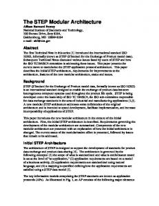
5.2 Processing sequence The implementation was carried out using Kiwivision MTM and MTMware software with Datacube MaxVideo-10 devices, namely a DigiMax video I/O card and a RoiStore-512K framestore card. The major steps in the procedure were as follows, with reference to the data pathways shown in Fig. 6 above. • Interlaced 512x512 images (1) were digitised by the DigiMax ADC and sent via the MAXbus pipeline to the RoiStore framestore (2). Alternatively, for verifying the procedure, test images could be created in the framestore and passed via the DigiMax DAC (3) for display on a monitor (4). • Non-interlaced 256x256 sub-images were then retransmitted from the RoiStore to the MTM via the pipeline (5) and directly distributed to the TCM and each TPM worker using the MTM MAXbus interface broadcast feature (6). • The worker process in the TCM and each TPM expanded its designated horizontal strip of the image from 8-bit integer to floating point (complex) and applied 1D row transforms to it. • The transformed rows were then regrouped by the TCM master process, by using the TCM’s ability to access all IDS memories (7). • The intermediate result thus formed was then redistributed to each TPM worker, by using the TCM to write it to one of its broadcast areas (8). • This time the worker process in the TCM and each TPM applied 1D transforms to its designated range of columns (rather than rows). • The TCM master process then assembled the resultant 2D transform by gathering up the vertical strips from each TPM worker to complete the transformed result, again using its ability to access all IDS memories (7). • The 2D transform was then scaled to 8-bit integer amplitudes and transmitted via the MTM MAXbus interface back out the pipeline (9) to the RoiStore, which captured the output data frame (256x256 non-interlaced). • The RoiStore then retransmitted the output image continuously (512x512 interlaced) to the DigiMax DAC (10) for display on a monitor (4).
Proc. SPIE Machine Vision Applications, Architectures, and Systems Integration III, Boston, 31 October 1994
8
5.3 Discussion The algorithm was implemented using a variable number of MTM transputers in a daisy-chain network topology, up to the system maximum of nine. Execution times were measured and processor efficiencies calculated. The results of the tests are reported elsewhere 5,6 . The FFT example serves well in showing how the MTM data broadcast modes can be used to advantage in simultaneously placing large blocks of data in the memories of multiple transputers for parallel processing. It should be noted that in a practical situation there could well be no need to calculate and retransmit the resultant output values for display.
6. CONCLUSION This paper has reported the internal design of the Kiwivision MTM Multi-Transputer Module with particular emphasis on its close coupling to a MAXbus pipeline. In particular, the ability to broadcast data into multiple IDS memories simultaneously is shown to be a strong feature which can be used to advantage for parallel processing when handling the large throughput of data often encountered in machine vision applications.
7. ACKNOWLEDGMENTS The development of the Kiwivision MTM multi-transputer module has largely been funded by the New Zealand Foundation of Research, Science, and Technology. Bob Valkenburg designed the hardware with technical assistance from Nigel Millar. Roger Clist developed the software and documentation with assistance from Bob Valkenburg and Olof Olsson. The Kiwivision implementation of the 2D Fast Fourier Transform was done by Richard Harman and Leon Raj as their Year 4 undergraduate project at the Department of Electrical and Electronic Engineering, University of Auckland, 1993, under the supervision of the authors. The MAXbus digital video interconnect standard was developed by Datacube, Inc. MAXbus, MaxVideo, and ImageFlow are trademarks of Datacube, Inc.
8. REFERENCES 1.
MaxVideo MAXbus Specification Doc. No. SP00-5, Datacube Inc., September 1988.
2.
R.J. Valkenburg, R. Tekiela, C.C. Bowman, O.J. Olsson, “Parallel implementation of vision algorithms on a hybrid pipelined/multitransputer architecture”, Automated Inspection and High Speed Vision Architectures II, Michael J. W. Chen, Editor, SPIE Proceedings Vol. 1197, Boston 1990.
3.
Kiwivision MTM Multi-Transputer Module User Reference Manual Industrial Research Limited, 1993 ISBN 0-478-07107-8.
4.
W.K. Pratt, Digital Image Processing, Wiley, 1978 ISBN 0-471-01888-0.
5.
R. Harman and L. Raj, Software development on a parallel-processor based machine vision computer, Year 4 Undergraduate Project Report, Department of Electrical and Electronic Engineering, University of Auckland, 1993.
6.
L. Raj and R. Harman, Application software for a parallel-processor-based machine vision system, Year 4 Undergraduate Project Report, Department of Electrical and Electronic Engineering, University of Auckland, 1993.
Proc. SPIE Machine Vision Applications, Architectures, and Systems Integration III, Boston, 31 October 1994
9