Electrical and Computer Engineering. Virginia ... to the clock network and the switching activity of a circuit. ... 10th International Conference on Application of Concurrency to System Design ..... [3] proposes retiming to solve this issue, which.
10th International Conference on Application of Concurrency to System Design
The Model Checking View to Clock Gating and Operand Isolation Jens Brandt and Klaus Schneider
Sumit Ahuja and Sandeep K. Shukla
Embedded Systems Group Department of Computer Science University of Kaiserslautern, Germany http://es.cs.uni-kl.de
FERMAT Lab Electrical and Computer Engineering Virginia Tech, Blackburg, VA, USA http://www.fermat.ece.vt.edu
propagation of switching activity through the circuit so that power consumption for changing the state of wires can be saved. While both techniques may involve area overhead and additional power for their own computations, they have shown to pay off the additional effort. In principle, all approaches are based on the following two steps: First, unnecessary computations are identified according to some heuristics. Second, a power reduction technique is applied to a circuit, which derives a new implementation that exploits the redundancy information from the first step but consumes less power, i. e. it chooses a better (w. r. t. power consumption) implementation with the same observable behavior. Basically, unnecessary computation has three sources: • The first one is the encoding of data: usually, not all combinations are used in a design. For example, consider a component which has two output ports, a Boolean flag which indicates whether the computation has been successful and the result itself. If the computation is not successful, the flag is reset, and the values at the other port does not carry any information. Hence, we are free to compute this signal, which aims to eliminate any computation that is only related to this part. • The second source is due to lazy evaluation: For example, if one operand of a multiplication operation is zero, the value of the other operand is irrelevant for the final result. Hence, one can eliminate any computation needed for the redundant part. Other examples for such components are multiplexers, where only the selected input must be computed. Closely related are alternatives in computation: instead of a dominant input, one has a choice between different variants that all give the same result. Hence, identifying unobservable (i. e. unnecessary) computations, which do not contribute to the final result, is the essential step for power optimization in this context. • The third source is related to the second one. Consider a register with enable signal: if its new value corresponds to the old one, one can either disable the register or recompute the old value. Whatever choice is made, one of the two inputs is redundant. Since the enable signal
Abstract—Clock gating and operand isolation are two techniques to reduce the power consumption in state-of-the-art hardware designs. Both approaches basically follow a two-step procedure: first, they statically analyze a hardware circuit to determine irrelevant computations. Second, all parts which are responsible for these computations are replaced by others that consume less power in the average case, either by dynamically gating clocks or by isolating operands. This paper focuses on the first phase, i. e. the computation of irrelevant computation. The core of our contribution is the definition of so-called passiveness conditions for each signal x, which indicate that the value currently carried by x does not contribute to the final result of the system. After showing how our theory can be generally used in the context of clock gating and operand isolation, we classify many state-of-the-art approaches and show that they are in fact conservative approximations of our general setting. Thereby, it defines the theoretical basis for adoption of these approaches in their entirety.
I. I NTRODUCTION Today’s embedded systems are more and more challenged by power issues. These challenges are not only due to the increasing number of portable devices, which are fed by batteries of limited capacity. Power consumption generally produces heat, a cause of many problems in embedded systems, which must fit into a predefined environment. Hence, in general, reducing the power consumption is one of the major goals while designing an embedded system. There are a lot of different techniques to save power in the hardware part of these systems. Voltage and frequency scaling can be used to trade performance for power consumption. However, the most popular approaches, which do not involve significant performance penalties, are currently clock gating [5, 30] and operand isolation [14]. They tackle a significant source of power consumption, which is related to the clock network and the switching activity of a circuit. Clock gating adds logic to dynamically disabling portions of the circuitry. Thereby, the clock network does not consume power in that part, which is generally worthwhile, since the network is known to account for one third of the total power in many state-of-the-art circuits. Furthermore, flip-flops in the deactivated part do not change state, and their switching power consumption goes to zero (only leakage currents are left). In contrast, operand isolation selectively blocks the 1550-4808/10 $26.00 © 2010 IEEE DOI 10.1109/ACSD.2010.22
181
plays a designated role for clock gating, stability of signals is usually considered separately, although it can be also seen as a special case of the second source, where one can choose between the computation of the enable signal and the register input [27]. In recent years, researchers have developed myriads of different approaches for clock gating and operand isolation (see Section IV). Not only the sheer number of them makes it difficult to gain a good overview of the field, but also the lack of a unified underlying theory for all of them. Many of these approaches use informal arguments or tests to validate their approach. However, even if some formal arguments are given, the underlying theory is made to show the correctness and feasibility of the particular approach and not to relate it to others. In this paper, we provide a general theory which can be used as a formal underpinning of clock gating and operand isolation procedures. Thereby, we give the basis for a formal verification of individual approaches and for the comparison and integration of several different ones. This paper is in the spirit of a classical paper by Steffen [32, 35], where a bridge between model checking and the data-flow analysis in classical compiler design was built. This link has influenced research in the connected areas: while compiler design got a new formal underpinning in terms of µ-calculus, model checking got access to the well-established and efficient algorithms using worklists and strongly connected components like [23, 34, 37] which lead to improved algorithms like [10, 11, 13] and [7, 22, 31, 40]. The core of our contribution is the definition of a passiveness condition psvx for each signal x, which indicates that the value currently carried by x does not contribute to the final result of the system. The approach presented in this paper is related to our previous work [8], where we defined a similar requiredness condition reqx , which was used for a static data-flow analysis of synchronous programs to speed up the program execution. The rest of the paper is structured as follows: The next section provides the syntax and the semantics of the propositional µ-calculus, which will serve us as formal foundation of our approach. Section III introduces our underlying theory on top of the µ-calculus, and a general algorithm to compute redundant computations of a hardware circuit. Then, Section IV compares existing approaches with this theory and shows the approximations that have been used in those approaches. Finally, Section V gives a short summary.
used to describe properties of labelled transition systems. Its original idea is due to Scott and de Bakker [17], while its current form was developed by Kozen [26] into the version most people use nowadays. In the following, we only give a short overview, which is sufficient for the rest of the paper. For more details, the interested reader is referred to [18– 20, 26, 33, 36]. In general, a transition system is described by a Kripke structure K = (I, S, R, L) with set of states S, a set of initial states I ⊆ S, a transition relation R ⊆ S × S, and a labeling function L, which returns the set of variables that hold in the considered state s ∈ S. In the µ-calculus, each formula describes a set of states of the transition system K. A propositional formula p selects exactly the set of states of the transition system T , where the labeling satisfies p. In addition to the usual propositional operators (which are interpreted as set operations) the µcalculus has more operators, which refer to the underlying transition system: If φ is a formula of the µ-calculus, ♦φ represents the set of states preK ∃ (φ), i. e. the states having a successor (w. r. t. the transition relation) in the set of states defined by φ. Similarly, �φ is the set of states having all successors in the set defined by φ, which is denoted by preK ∀ (φ). Additionally, µx. Φ(x) is the least fixpoint of function Φ, and νx. Φ(x) is its greatest fixpoint. Sometimes more operators can be defined, which are syntactic sugar and can be reduced to the mentioned ones (even the operators above are not a minimal base). Formally, we define for a label x, formulas φ and ψ, and KxQ as the operation of marking all states of Q by x in K: • • • • • • • •
JxKK = {s ∈ S | x ∈ L(s)} J¬φKK = S \ JφKK Jφ ∧ ψKK = JφKK ∩ JψKK Jφ ∨ ψKK = JφKK ∪ JψKK J♦φKK = preK ∃ (φ) J�φKK = preK (φ) T∀ Jµx. φKK = {Q ⊆ S | JφKKxQ ⊆ Q} S Jνx. φKK = {Q ⊆ S | Q ⊆ JφKKxQ }
In the following, we use a more general variant of the traditional µ-calculus which is commonly referred to the vector µ-calculus [10, 12, 33]. In contrast to the plain version, it describes mutually dependent fixpoints in form of equation systems, which may be exponentially more succinct than the unfolded µ-calculus formulas. This extension adds no further expressiveness, but it can make the system description exponentially more succinct. In the vector µcalculus, we can define several sets of states by a system of mutually dependent fixpoints:
II. V ECTOR µ-C ALCULUS The µ-calculus is generally considered to be the underlying formalism for model-checking [18–20, 33], since most temporal logics, in particular CTL* (and thereby, CTL and LTL) can be translated to the µ-calculus (which can therefore be used as some kind of ‘assembler language’ for verification) [15, 33]. Basically, it is a temporal logic which can be
x1 xn
182
σ1
= .. .
σn
=
Φ1 (x1 , . . . , xn ) (1) Φn (x1 , . . . , xn )
Thereby, σi is a placeholder for either µ or ν. The notation σ xi =i Φi means that xi should be the least (if σi = µ) or greatest fixpoint (if σi = ν) of the function, where all other xj with i 6= j are determined by the other equations. Full details on the semantics as well as on model-checking algorithms can be found in [33]. Provided that the Boolean circuit has been translated to a Kripke structure, any model checker that supports the vector µ-calculus (e. g. the Averest system1 ) can be used for the computation of the fixpoint solutions for xi . Furthermore, the underlying theory of vector µ-calculus model checking [33] also answers questions about the feasibility and complexity of the computation. If the functions on the righthand side are all continuous, the least (greatest) fixpoint can be computed according to the iteration described by the Tarski-Knaster theorem [25, 38]: starting with the least (greatest) value and then reevaluating the functions Φ until a fixpoint is reached. Due to their monotonicity, we get a decreasing chain of lower (upper) bounds of the final values. The complexity of this computation is linear w. r. t. the size of the Kripke structure.
of the outputs can be weakened if there is a redundancy in the output encoding that implies that not all outputs are needed in all steps. The definition of psvx for local signals x is more complicated and its main idea is to follow the data dependencies in the circuit in reverse direction: the condition is determined for a signal whose successors have been already processed. In the following, we first consider the purely combinational part of the circuit. Before we explain the general rule, we study two simple examples in advance. A 2-to-1 multiplexer (MUX) has a single output signal y and three input signals x0 , x1 and s. Whenever s is true, the input x1 is forwarded to y; otherwise x0 . Hence, we can write y = if(s) x1 else x0 as a textual representation of this block. Provided that the passiveness condition of its output y is psvy , the passiveness conditions of its three inputs are as follows: psvx0 psvx1 psvs
= = =
psvy ∨ s psvy ∨ ¬s psvy ∨ (x0 ↔ x1 )
(2)
If the output of the multiplexer is passive, all the inputs are also passive. Otherwise, if the first line is selected, the other one is passive and vice versa. If both inputs are the same, any selection results results in the same output and the selector input is therefore passive. As a second example, consider a tristate element, which has a single output signal y and two input signals x and en. Whenever en is true, the input is forwarded to the output y. Hence, y = if(en) x. Provided that the passiveness condition of its output y is psvy , the passiveness condition of its inputs are as follows:
III. PASSIVENESS C ONDITIONS Passiveness conditions and their approximations, which will be described in the following sections, can be used in the synthesis step. Our definitions are the basis for the dynamic removal of passive parts, which improves energy efficiency of the hardware circuit. A. Identifying Unnecessary Computations In a hardware circuit, all wires and registers (in particular all local ones) have a value in each cycle. In the following, we will use the term signal for the sequence of values that are carried by them. Thereby, we do not fix the type of the carried values to Booleans, but allow arbitrary finite types so that wires and registers can be bundled to bit-vectors. This not only reduces the size of the model but also models the situation appropriately, if a set of wires or registers can be gated simultaneously by a single control signal. As already outlined in the introduction, an essential step of clock gating and operand isolation is the determination of unnecessary computation, i. e. when a signal is not needed for the computation of the final outputs, which will be called passive signal in the following. The computation of the situations when signals are passive is the problem we want to tackle in this subsection. To this end, we define a passiveness condition psvx for every signal x, which should hold exactly when the current value of x is not required for the computation of outputs in any subsequent cycle. In the general case, all outputs yi of the system should be computed in all steps. Thus, we define psvyi = false for all outputs yi . These definitions of the passiveness condition
psvx psven
= psvy ∨ ¬en = psvy
(3)
We observe the same underlying structure: The passiveness of the inputs depends on their influence to the outputs and their own passiveness. Before we give a formal definition for that, we first formalize the influence to the outputs, which is generally known as the ODC (observability don’t care) condition and which is basically the approach presented in [3]. Definition 1 (Observability Don’t Care): Assume that true false f |x ( f |x ) is the positive (negative) cofactor of function f w. r. t. x, i. e. the function f where x has been substituted with true (false). Then, the ODC observability don’t care condition odcf (x) for a function f with a single Boolean input x and a Boolean output y is defined as � � true false odcf (x) := f |x ↔ f |x In general, the ODC observability don’t care condition odcf (x) for a function f with input x ∈ D1 and output y ∈ D2 of an arbitrary datatype, we have with the help of
1 http://www.averest.org
183
v
the general cofactor ( f |x is the function f where the variable x is substituted by v): odcf (x) :=
y
x
f g
_
^
y=
p/q
v f |x
y∈D2 v∈D1
Now, we are in the position to the define passiveness in a combinational context. Definition 2 (Combinational Passiveness): The passiveness condition of a combinational circuit implementing a function f is determined by the disjunction of the passiveness conditions of its output y = f (x1 , . . . , xn ) and its ODC conditions:
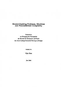
Figure 1.
The second example illustrates the feedback. Consider two simple registers q0 and q1 without enable signals, which are are chained. The output of the second one is connected to the global output y and fed back as the input of the first one x, i. e. next(q0 ) = q1 , next(q1 ) = q0 and y = q1 . To cope with the cyclic dependencies, we use the fixpoint operator νx.f (x), which returns the greatest fixpoint of the given function f . This is exactly the operation that we need in our computation, since we want to maximize the points of time, where psvx for some signal x holds:
psv(f, x) := psvy ∨ odcf (x) This definition obviously models our intention, since any unobservable computation is not needed for the final result so that it can be defined as passive. Hence, for the combinational part of the circuit, we use the ODC sets to define the passiveness condition. Unfortunately, this straightforward computation is not possible for general sequential circuits, where we have data dependencies across cycles, which result from delay elements such as registers. Another problem is the feedback of signals, which makes the definition of the passiveness conditions as presented above recursive. For the behavior of the system itself, this feedback does not pose any problems, since the new value is fed back only in the following clock cycle. In order to determine psvx in the general case, we therefore need a more powerful formalism, which allows us to reason about the cyclic dependencies. As already mentioned in the introduction, it is well-known that most data-flow analyses can be represented as cyclic equation systems whose solution is a least or greatest fixpoint which can be solved by a fixpoint computation similar to modelchecking algorithms [6, 13, 33]. In particular, the formal representation as well as the final solution can be done by means of the vector µ-calculus. Once again, we first consider two examples before introducing the general definition. As a first example, consider a simple register with enable signal. It has an output signal q and two input signals p and en. Whenever en is true in the current cycle, the current value of the other input p is stored and will be the output q of the following cycle. Hence, we can write next(q) = if(en) p else q in a textual representation. To cope with the dependency across the clock cycle, we use the box operator of the µ-calculus: �psvx states that in all successor states x is passive, which gives us the following results for the register: psvp psven
= =
�psvq ∨ ¬en �psvq ∨ (p = q)
General Circuit Structure
psvq0 psvq1
ν
= ν =
�psvq1 �psvq0 ∧ psvy
In general, the passiveness conditions psvx of a circuit can be computed as follows: Definition 3 (Passiveness): Given a circuit with input signals x0 , . . . , xn , output signals y0 , . . . , ym with yi = fi (x0 , . . . , xn , q0 , . . . , ql ), and a set of delay elements with inputs p0 , . . . , pl and outputs q0 , . . . , ql where next(qi ) = pi and pi = gi (x0 , . . . , xn , q0 , . . . , ql ) (see Figure 1), the following system of mutually dependent fixpoint equations describes the desired psvx conditions for the inputs xi and the delay elements qi :
psvx0
= .. .
psvxn
=
psvq0
= .. . ν = ν = .. . ν =
psvql psvp0 psvpl
ν
Vm
i=0
psv(fi , x0 ) ∧
Vl
i=0
psv(gi , x0 )
Vm Vl psv(f , x ) ∧ psv(g , x ) i n i n i=0 i=0 Vm Vl i=0 psv(fi , q0 ) ∧ i=0 psv(gi , q0 ) Vm Vl psv(f , q ) ∧ psv(g , q ) i l i l i=0 i=0 �q0 �ql
The first set of equations defines the passiveness conditions for the input signal: they are passive according to Definitions 2 and 3 iff the output of function fi or gi is passive or the input is not needed for the computation. Similarly, the signals of the delay elements are passive if they are not needed for the computation of values in the following step.
(4)
184
x1
0 1
p0 /q0
+1
p1 /q1 y
p2 /q2
x2
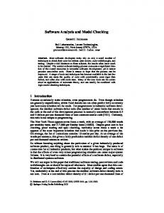
Figure 2.
Example: Passiveness Condition
The underlying µ-calculus theory gives us some answers about the computation. The given equation system has a uniquely determined greatest fixpoint, since all functions are continuous by construction. The monotonicity (w. r. t. the order false < true) can be easily seen in the Definitions 2 and 3 since all occurrences of the passiveness conditions are positive, and they are only connected in conjunctions and disjunctions (which are monotonic). Continuity immediately follows from monotonicity and the finite domain of all passiveness conditions. Figure 2 gives another example, which uses three registers q0 , q1 (storing some numbers) and q2 (storing a Boolean). p0 next(q0 ) p1 next(q1 ) p2 next(q2 ) y
= = = = = = =
ν
�psvq1 psvp0 ∨ q2 �psvq1 ∨ (p1 = q1 ) �psvq2 psvp0 ∨ (x1 = q1 ) �psvq2 ∨ (p2 = q2 ) ¬q2 ∨ psvp0 psvp2
psvp0 psvq0 psven0
= �psvq0 ν = psvp1 ∧ psvy ν = �psvq0 ∨ (p0 = q0 )
psvp1 psvq1 psven1
= ν = ν =
psvp2 psvq2 psven2
= ν = ν =
psvx1 psvx2
= ν =
ν
ν
ν
false
psvp0 psvq0 psven0
= = =
false false (p0 = q0 )
psvp1 psvq1 psven1
= = = =
psvp2 psvq2 psven2
= = = =
psvx1 psvx2
= 2 = false
en0
ν
= false
=
�q2 p2 q2 �q2 ∨ (p1 = q1 ) p2 ∨ (p1 = q1 ) false (x1 = q1 ) (p2 = q2 ) ¬q
The passiveness conditions of the previous section can be used in the second step of our general technique to reduce the number of gates operating in a cycle and thereby the power consumption of the circuit. Clock gating uses this information as follows: whenever psven holds for an enable signal en of a register with input p and output q, it can be set to false so that the connected register does not consume energy for the current clock cycle. With Equation 4, one gets: = =
en ∧ ¬psven en ∧ ¬�psvq ∧ ¬(p = q)
(5)
For a tristate element, Equation 3 can be used to strengthen the enable signal as follows:
Assume that the registers could be now controlled by enable signals en0 , en1 and en2 , respectively. Then, with the help of Definition 3, the following passiveness conditions can be retrieved: psvy
psvy
B. Optimizing Power Efficiency
if(q2 ) x1 else q1 p0 r0 + 1 p1 x2 p2 q0
en0
= en ∧ ¬psven = en ∧ psvy
(6)
For operand isolation, a similar approach is possible: Whenever psvs holds for a signal s, it can be set to its previous value pre(s) (e. g. by introducing an additional transparent latch) in order to save energy for the current cycle. s0 = if(psvs ) pre(s) else s
(7)
The transformed circuit generally saves power since only required register updates and signal changes are computed. As a result, the power consumption of the actual circuit is reduced. However, a potential drawback may be the additional complexity of the passiveness signals due to the additional effort for their computation: The functionality needs more chip area, and obviously it consumes power on its own. Hence, for a practical use, one has to carefully balance the additional effort against the savings.
By simple substitution, this can be simplified to: 185
This is due to the monotonicity of the passiveness conditions. The final result is thereby guaranteed to be smaller or equal to the one defined in the previous section. For examples of industrial size, a monolithic computation of the ODC conditions usually results in conditions which are too complex for practical usage. For these examples, the only feasible approach is an approximation, which only considers designated components of the circuit structure, e. g. the steering logic. In general, this approximation first decomposes the circuit into several parts and computes the passiveness from them. Then, these conditions are subsequently reassembled. Since combinational passiveness is defined by the ODC conditions, this approach directly follows the compositional computation of ODC conditions. In addition to the exact solution, which is given in [16], there are several conservative approximations of the ODC conditions, which can be also exploited for the passiveness conditions. A very simple, but coarse approximation [3, 9] is to reassemble the local ODC conditions by assuming that for a fan-out of a signal x to x1 , . . . , xn , the passiveness condition of x is
C. Conservative Approximations Section III-A introduced a general framework for determining unnecessary computations. Based on them, Section III-B defined some circuit transformations which generally reduce its power consumption. In principle, clock gating and operand isolation can be done by simply using the presented definitions and a model checker (which supports the vector µ-calculus). It computes the desired strengthening of signals, which enable signals and isolate operands in a circuit. However, real-world examples are usually too complex for such a naive computation, and the conditions defined above tend to be too aggressive so that the generated overhead is generally not the optimal solution. Therefore, we do not propose to use it in the form presented above as an alternative to existing clock-gating approaches. It should merely serve as an underlying theory for practical clock gating approaches, which can be shown to be instances of the approach presented above (and therefore to be correct). Before we relate various approaches to power reduction to our theory in Section IV, we first show conservative approximations and heuristics of the passiveness definitions, which are the basis for practical implementations. While the static analysis is simpler (so that it is manageable at all) or the dynamic overhead is smaller (so that the total power reduction is better), these approximations compute more values than necessary. Formally: Definition 4 (Approximation of Passiveness): The condi˜ x is a conservative approximation of the passiveness tion psv condition psvx , iff
psvx =
This is in fact an approximation, as the following example reveals. It has a single Boolean output signal z and two input signals of arbitrary type x1 and x2 , which are actually unnecessary for the computation of z, since the circuit represents a tautology: z y1 y2
Similar to the passiveness conditions themselves, we can distinguish two different classes of approximations which either refer to the combinational (Section III-C2) or the sequential part (Section III-C3) of the definition. 1) Raising the Abstraction Level: A very simple approximation is the bundling of variables to a single variable (e. g. bundling Booleans values into bitvectors), which simplifies the computation by reducing the number of variables. This abstraction is made when a set of signals should be driven by a single enable signal (e. g. when they should be grouped in a component). The passiveness signal for this composition x is simply the conjunction of the individual signals xi , i. e. : n ^
psvxi
psvxi
i=1
˜ x → psvx ∀x. psv
psvx =
n ^
= = =
y1 ∨ y2 (x1 = x2 ) x1 6= x2
Instead of the precise psvx1 = psvx2 = true, these definitions give the result that the input signals x1 and x2 are never passive. psvz psvy1 psvy2 psvx1 psvx2
= false = psvz ∨ y2 = psvz ∨ y1 = (psvy1 ∨ (x1 6= x2 )) ∧ (psvy2 ∨ (x1 = x2 )) = (x1 6= x2 ) ∧ (x1 = x2 ) = false = (psvy1 ∨ (x1 6= x2 )) ∧ (psvy2 ∨ (x1 = x2 )) = (x1 6= x2 ) ∧ (x1 = x2 ) = false
3) Approximating the Fixpoint: The computation of the fixpoint generally follows the Tarski-Knaster theorem [25, 38]. The greatest fixpoint can be computed by starting with the greatest value (in our case true) and then reevaluating the passiveness conditions until a fixpoint is reached. Due to their monotonicity, we get a decreasing chain of upper bounds > = x0 ≥ x1 ≥ x2 ≥ . . . ≥ x ˇ of the final value x ˇ. Since only lower bounds are conservatively correct
(8)
i=1
2) Approximating the ODC Conditions: The second approximation can be made when defining the combinational passiveness (see Definition 2). Instead of the precise definition, any function that is smaller or equal (w. r. t. the order false < true) to the defined one, yields a correct solution.
186
solutions (according to Definition 4), we cannot simply stop the computation prematurely. Nevertheless, the computation of the fixpoint can be simply bounded by unrolling the equation system of passiveness conditions several times, and then conservatively approximating the remaining passiveness conditions on the right-hand side by false. Again, this is possible due to the monotonicity of the functions, which the passiveness conditions are built of. Afterwards, the passiveness conditions are acyclic so that they can be straightforwardly computed. Basically, one approximates the model checking by its bounded counterpart, which significantly reduces the complexity of the computation. Finally, a corner case of the unrolling approach is to completely omit it, which corresponds to replacing all occurrences of other passiveness conditions on the righthand side by false. This approximation (which will be called combinational approximation in the following) is made by many researchers, which will be seen in the following section. In this case, we do not need the µ-calculus at all for the passiveness conditions, since the equation system is a straightforward definition (provided that there are no combinational loops, which have been excluded in the whole paper).
primary outputs psvyi multiplexer psvx0 psvx1 psvs tristate register
psvy psven psvx psven
fan-out transp. logic
psvy psvxi
= = = = ≤ = = = ≤ = ≤ = =
false psvy ∨ s psvy ∨ ¬s psvy ∨ psvy ∨ (x0 = x1 ) psvy ∨ ¬en psvy psvyi ∨ ¬en psvyi ∨ ¬en ∨ �¬psvy false psvyi ∨ (x = y) psvy1 ∧ . . . ∧ psvyn psvy
The restriction has several practical reasons: first, the passiveness conditions can be computed very easily (see section on compositional ODC and the examples in Section III-A) and second, the passiveness conditions match already existing signals so that they do not need to be computed separately, since they correspond to the selection/enable signals of the steering logics. The only implementation problem of these approaches is that the enable signal of register is computed one cycle too late. [3] proposes retiming to solve this issue, which represents a limited form of predecessor computation in our µ-calculus approach: whereas retiming of a signal can only be done if it does not directly depend on inputs, �φ always gives a result. Guarded evaluation as presented in [39] basically follows the same principle, but it is slightly more general: it does not only consider the steering logic of the circuit, but all combinational elements are analyzed. In [29] an automated approach for RT-level operand isolation is presented. Basically, it follows the same approach for identifying the unnecessary computation as the ODCbased clock gating, but it exploits this for operand isolation as described in Section III-B. In particular, for its analysis the approach assumes that the enable signal of all registers is true. Hence, it only considers combinational information in order to avoid complex control logic overhead.
IV. R ELATING E XISTING A PPROACHES In this section, we use the basic theory developed in Section III to explain and compare state-of-the-art clock gating and operand isolation approaches. A. ODC-Related Approaches The approach presented in [3, 24] only considers the data inputs of the steering logics of a circuit (inputs of multiplexers, tristate elements and registers with enable signal). The basic idea is that when a particular line is selected, the rest of the lines become unobservable for computing all the other signals in a cycle. So, one could then propagate this information backwards to signals that compute these unobservable signals, make them unobservable, and so on. In contrast to the steering logics, the remaining combinational part of the circuit is considered to be transparent for redundancies: if some output is needed, then all its inputs are also needed. Passiveness conditions are only propagated over steps, i. e. this approach makes use of the combinational approximation presented in Section III-C3. Although this approach is considered to do sequential clock gating (since it considers registers), it only uses combinational information in our passiveness framework. With the input/output port labeling used in the previous section, it uses the following approximations (if not matching, our definitions are given on the right-hand side of the less-than operators):
B. STC-Related Approches Besides ODC, stability conditions (STC) are considered as a second source of unnecessary computation in classical clock gating approaches. Within our passiveness approach of Section III-A, it does not play a designated role: since enable signals of registers are handled like any other signal in our approach (see Equation 4), their passiveness condition reflects both, ODC and STC. This view is more or less equivalent to [21], where ODC and STC are combined and existing clock gating is reused. In our approach, exactly the same thing happens: we strengthen the existing enable signal of a register by ODC and STC conditions (see Section III-B),
187
g0 (x) = true → g1 (x) = true →
and existing enable signals influence preceding and succeeding registers. Nevertheless, there is yet an approximation compared to the µ-calculus description, which makes the approach more scalable to real-world examples: While we add the stability condition p = q as a min-term to the passiveness condition (see Equation 4), this condition is approximated by deasserting all enable signals of the registers in the combinational cone of influence. In [4] the stability condition is derived from an explicit state machine model of the circuit. It is scanned for selfloops of states, which are subsequently used to gate the clock of the overall circuit. Thereby, it also checks the precise equation i = q, but it does not consider ODC conditions. In [1], unobservable output behavior of registers and the information whether the stability of one register influences another one, is tried to be found by an analysis based on model checking. Thus, no structural information is used by the approach, but the designer proposes dependencies, which are verified by a model checker. In some situations, these correlations exist even if structural analysis is able to find the behavioral relationship between two enabling conditions of the registers. This is due to the fact that this approach can exploit the set of actually reachable states of the circuit, which are computed by the model checking procedure.
f (x) = false f (x) = true
(9)
Hence, the circuit can be transformed to eny = ¬(g0 (x) ∧ ¬g1 (x)) next(y) = if(eny ) x next(p0 ) = g0 (x) next(p1 ) = g1 (x) next(z) = if(p0 ) false else if(p1 ) true else f (y1 , . . . , yn ) For these circuits, the passiveness conditions can be computed as follows: Thereby, assume that the result is never passive, i. e. psvz = false. Then, applying the definitions of Section III-A yields: = = = = = = = =
psvp0 psvp1 psvy psveny
psvx
false false ¬(p0 ∨ p1 ) �psvy ∨ (x = y) �¬(p0 ∨ p1 ) ∨ (x = y) ¬(g0 (x) ∧ ¬g1 (x)) ∨ (x = y) psvp0 ∧ psvp1 ∧ (psvyi ∨ ¬eny ) false
Hence, the first part of the passiveness condition corresponds to the enable signal assigned by precomputation. Thus, it shows the correctness of the precomputation approach. The second part reveals that even more clock ticks can be gated, which are due to stability conditions. There is another precomputation architecture presented in [2], which has a different structure. It divides the register bank for the signal y into two sections yi and yj , where only the second part is considered for clock gating. The basic idea is to infer conditions, where the first part is sufficient for the evaluation so that the second part does not need to be loaded. Hence, we have the following structure:
C. Precomputation Precomputation [2], as the name suggests, computes some values early, before they are actually needed in a circuit. This information is then used to reduce the switching activity of a circuit. For example, in a processor pipeline, the instruction word determines which functional units are used along the pipeline [28]. After the initial instruction fetch and decode, it is known many cycles in advance which stages can be deactivated. In general, this situation is quite common if circuits contain chains of sequential elements which are activated due to some predefined scheme. Most approaches avoid precomputation completely, since it may involve much complexity in the analysis and potential drawbacks in the generated logic intended for power saving. Precomputation was originally presented in [2], where the authors try to save power by precomputing a quick guess of a signal. If successful, the operands that would have been used in the normal case do not need to be loaded into registers. Thereby, precomputation assumes that the original circuit consists of a register bank y buffering the inputs, i. e. next(y) = x, and the actual function f , whose result is stored in bank z, i. e. next(z) = f (y). Then, the basic idea is to precompute two functions g0 and g1 , which approximate the behavior of f : g0 is only true if f is false, and g1 is only true if f is true. If both functions are false, nothing is said about f .
next(yi ) = enyj = next(yj ) = next(z) =
xi ¬odcf (yj ) if(enyj ) xj f (yi , yj )
Again, assume that the output is never passive, i. e. psvz = false. Computing the passiveness conditions yields: psvyi psvyj psveny
j
= = = =
false (by construction) ¬odcf (yj ) (by construction) �psvyj ∨ (x = y) �¬odcf (yj ) ∨ (x = y)
Not surprisingly, the first part of the passiveness condition for yj is the solution proposed in [2]: it is the precomputation of the ODC condition, which is expressed by the � operator.
188
V. C ONCLUSIONS AND F UTURE W ORK In this paper, we presented a general framework for comparing and verifying existing clock gating approaches. It is based on the definition of passive signals, i. e. signals that do not carry any information needed to determine the final result of the circuit. We gave a formal definition built on top of the vector µ-calculus, which is exactly the formalism needed to describe the problem precisely. Finally, we compared previous work related to our general setting presented in Section III. Thereby, one can notice that all these approaches are in fact approximations of our approach, which were made in order to reduce the complexity of the computation or the clock gating logic (so that real-world examples can be handled). An important fact that can be observed from the comparison is that some features of the general approach are not exploited by any of the existing approaches. For example, precomputation only analyzes the sequential information of the circuit up to a given limit. In the model-checking view, we can have an unbounded number of steps. Furthermore, no approach generally supports (sequential) cyclic dependencies. They always assume that the circuit is acyclic. If a feedback is present, it is abstracted conservatively. As already highlighted in the paper, the formalization given in Section III is not meant to be a blue print for a real implementation, but it should serve as a general framework for the verification and comparison of other approaches, which make conservative approximations in order to deal with the complexity. Nevertheless, the approach might also give another view to clock gating and operand isolation and may serve as a starting point for new approaches. Hence, future work might be the reuse and evaluation of techniques from the model checking domain, e. g. abstractions and bounded model checking.
[5]
[6]
[7]
[8]
[9]
[10]
[11]
R EFERENCES [1] S. Ahuja and S. Shukla. MCBCG: Model checking based sequential clock-gating. In IEEE International High Level Design Validation and Test Workshop (HLDVT), pages 20–25, San Francisco, California, USA, 2009. IEEE Computer Society. [2] M. Alidina, J. Monteiro, S. Devadas, A. Ghosh, and M. Papaefthymiou. Precomputation-based sequential logic optimization for low power. In J.A.G. Jess and R.L. Rudell, editors, International Conference on Computer Aided Design (ICCAD), pages 74–81, San Jose, California, USA, 1994. IEEE Computer Society. [3] P. Babighian, L. Benini, and E. Macii. A scalable algorithm for RTL insertion of gated clocks based on ODCs computation. IEEE Transactions on Computer-Aided Design Of Integrated Circuits and Systems, 24(1):29– 42, January 2005. [4] L. Benini and G. De Micheli. Automatic synthesis of low-power gated-clock finite-state machines. IEEE
[12]
[13]
[14]
189
Transactions on Computer-Aided Design of Integrated Circuits and Systems, 15(6):630–643, June 1996. L. Benini and G. De Micheli. Dynamic Power Management: Design Techniques and CAD Tools. Kluwer, Norwell, Massachusetts, USA, November 1997. S. Berezin, E.M. Clarke, S. Jha, and W.R. Marrero. Model checking algorithms for the µ-calculus. Technical Report CMU-CS-96-180, Carnegie Mellon University, September 1996. ftp://reports.adm.cs.cmu.edu/usr/anon/1996/CMU-CS96-180.ps. R. Bloem, H.N. Gabow, and F. Somenzi. An algorithm for strongly connected component analysis in n log n symbolic steps. In W.A. Hunt and S.D. Johnson, editors, Formal Methods in Computer-Aided Design (FMCAD), volume 1954 of LNCS, pages 37– 54, Austin, Texas, USA, 2000. Springer. J. Brandt and K. Schneider. Static data-flow analysis of synchronous programs. In R. Bloem and P. Schaumont, editors, International Conference on Formal Methods and Models for Co-Design (MEMOCODE), pages 161–170, Cambridge, Massachusetts, USA, 2009. IEEE Computer Society. R.K. Brayton, R. Rudell, A. Sangiovanni-Vincentelli, and A.R. Wang. MIS: A multiple-level logic optimization system. IEEE Transactions on Computer-Aided Design of Integrated Circuits and Systems, 6(6):1062– 1081, November 1987. R. Cleaveland, M. Klein, and B. Steffen. Faster model checking for the modal µ-calculus. In G. von Bochmann and D.K. Probst, editors, Computer Aided Verification (CAV), volume 663 of LNCS, pages 410– 422, Montréal, Québec, Canada, 1993. Springer. R. Cleaveland and B. Steffen. Computing behavioral relations, logically. In J. Leach Albert, B. Monien, and M. Rodriguez Artalejo, editors, International Colloquium on Automata, Languages and Programming (ICALP), volume 510 of LNCS, pages 127–138, Madrid, Spain, 1991. Springer. R. Cleaveland and B. Steffen. A linear-time model checking algorithm for the alternation-free µ-calculus. In K.G. Larsen and A. Skou, editors, Computer Aided Verification (CAV), volume 575 of LNCS, pages 48–58, Aalborg, Denmark, 1992. Springer. R. Cleaveland and B. Steffen. A linear-time model checking algorithm for the alternation-free µ-calculus. Formal Methods in System Design (FMSD), 2(2):121– 147, April 1993. A. Correale. Overview of the power minimization techniques employed in the IBM PowerPC 4xx embedded controllers. In M. Pedram, R.W. Brodersen, and K. Keutzer, editors, International Symposium on Low Power Electronics and Design (ISLPED), pages 75–80, Dana Point, California, USA, 1995. ACM.
[15] M. Dam. CTL* and ECTL* as fragments of the modal µ-calculus. Theoretical Computer Science (TCS), 126(1):77–96, 1994. [16] M. Damiani and G. De Micheli. Observability don’t care sets and boolean relations. In International Conference on Computer Aided Design (ICCAD), pages 502–505, Santa Clara, California, USA, 1990. IEEE Computer Society. [17] J.W. De Bakker. Least fixed points revisited. Theoretical Computer Science (TCS), 2(2):155–181, 1976. [18] E.A. Emerson. Model checking and the µ-calculus. In N. Immerman and P. Kolaitis, editors, Workshop on Descriptive Complexity and Finite Models, volume 31 of DIMACS, pages 185–214, Princeton, New Jersey, USA, 1997. American Mathematical Society. [19] E.A. Emerson, C.S. Jutla, and A.P. Sistla. On modelchecking for fragments of µ-calculus. In C. Courcoubetis, editor, Computer Aided Verification (CAV), volume 697 of LNCS, pages 385–396, Elounda, Crete, Greece, 1993. Springer. [20] E.A. Emerson, C.S. Jutla, and A.P. Sistla. On model checking for the µ-calculus and its fragments. Theoretical Computer Science (TCS), 258(1-2):491–522, 2001. [21] R. Fraer, G. Kamhi, and M.K. Mhameed. A new paradigm for synthesis and propagation of clock gating conditions. In L. Fix, editor, Design Automation Conference (DAC), pages 658–663, Anaheim, California, USA, 2008. ACM. [22] R. Gentilini, C. Piazza, and A. Policriti. Computing strongly connected components in a linear number of symbolic steps. In Symposium on Discrete Algorithms (SODA), pages 573–582, Baltimore, Maryland, USA, 2003. ACM/SIAM. [23] B. Jiang. I/O-and CPU-optimal recognition of strongly connected components. Information Processing Letters, 45(3):111–115, 1993. [24] H. Kapadia, L. Benini, and G. De Micheli. Reducing switching activity on datapath buses with controlsignal gating. IEEE Journal of Solid-State Circuits, 34(3):405–414, March 1999. [25] B. Knaster. Un théorème sur les fonctions d’ensembles. Ann. Soc. Polon. Math., 6:133–134, 1928. [26] D. Kozen. Results on the propositional µ-calculus. Theoretical Computer Science (TCS), 27(3):333–354, December 1983. [27] Y. Kuo, S. Weng, and S. Chang. A novel sequential circuit optimization with clock gating logic. In S.R. Nassif and J.S. Roychowdhury, editors, International Conference on Computer-Aided Design (ICCAD), pages 230–233, San Jose, California, USA, 2008. ACM/IEEE Computer Society. [28] H. Li, S. Bhunia, Y. Chen, T.N. Vijaykumar, and K. Roy. Deterministic clock gating for microprocessor
[29]
[30]
[31]
[32]
[33]
[34]
[35]
[36]
[37]
[38]
[39]
[40]
190
power reduction. In International Symposium on HighPerformance Computer Architecture (HPCA), pages 113– 122, Anaheim, California, USA, 2003. IEEE Computer Society. M. Münch, B. Wurth, R. Mehra, J. Sproch, and N. Wehn. Automating RT-level operand isolation to minimize power consumption in datapaths. In Design, Automation and Test in Europe (DATE), pages 624– 631, Paris, France, 2000. ACM. M. Pedram and J.M. Rabaey, editors. Power Aware Design Methodologies. Kluwer, Norwell, Massachusetts, USA, June 2002. K. Ravi, R. Bloem, and F. Somenzi. A comparative study of symbolic algorithms for the computation of fair cycles. In W.A. Hunt and S.D. Johnson, editors, Formal Methods in Computer-Aided Design (FMCAD), volume 1954 of LNCS, pages 143–160, Austin, Texas, USA, 2000. Springer. D.A. Schmidt. Data flow analysis is model checking of abstract interpretations. In Principles of Programming Languages (POPL), pages 38–48, San Diego, California, USA, 1998. ACM. K. Schneider. Verification of Reactive Systems - Formal Methods and Algorithms. Texts in Theoretical Computer Science (EATCS Series). Springer, 2003. M. Sharir. A strong-connectivity algorithm and its application in data flow analysis. Computers and Mathematics with Applications, 7(1):67–72, 1981. B. Steffen. Data flow analysis as model checking. In T. Ito and A.R. Meyer, editors, Theoretical Aspects of Computer Software (TACS), volume 526 of LNCS, pages 346–364, Sendai, Japan, 1991. Springer. C. Stirling and D.J. Walker. Local model checking in the modal µ-calculus. Theoretical Computer Science (TCS), 89(1):161–177, 1991. R. Tarjan. Depth first search and linear graph algorithms. SIAM Journal on Computing, 1(2):146–160, 1972. A. Tarski. A lattice-theoretical fixpoint theorem and its applications. Pacific Journal of Mathematics, 5(2):285– 309, 1955. V. Tiwari, S. Malik, and P. Ashar. Guarded evaluation: Pushing power management to logic synthesis/design. In M. Pedram, R.W. Brodersen, and K. Keutzer, editors, International Symposium on Low Power Electronics and Design (ISLPED), pages 221–226, Dana Point, California, USA, 1995. ACM. A. Xie and P.A. Beerel. Implicit enumeration of strongly connected components and an application to formal verification. IEEE Transactions on Computer Aided Design of Integrated Circuits and Systems, 19(10):1225–1230, October 2000.