The OneSAF Product Line Architecture: An Overview Of The Products And Process Robert L. Wittman Jr. Lead Modeling and Simulation Engineer MITRE CORPORATION 3045 Technology Parkway, Orlando, FL 32826 321-235-7601
[email protected]
Anthony J. Courtemanche OneSAF System Architect SAIC 12901 Science Drive Orlando, FL 32826-3014 321-235-7623
[email protected] Abstract. The U.S. Army is developing OneSAF as its next generation entity level simulation. The Army intends to use the simulation across the Advanced Concepts and Requirements (ACR), Training, Exercises, and Military Operations (TEMO), and Research, Development, and Acquisition (RDA) domains. It will allow the simulation of individual battlefield components such as soldiers, tanks, and helicopters through military units to the Brigade level operating in either a completely automated mode or under human control. As part of the acquisition and development of OneSAF the U.S. Government is using a task order acquisition plan. Under this plan the government, in an Architecture Integrated Product Team (IPT) environment, developed an initial Product Line Architecture Framework (PLAF) that was used to inform and guide the respective bidders for the OneSAF Architecture and Integration (A&I) contract. This A&I contract was let in May of 2001. At this time the A&I contractor took the lead in the evolution and further development of the architecture. This paper describes the processes and products that define the current OneSAF architecture and how it is intended to evolve over the next year. 1.
INTRODUCTION
The One Semi-Automated Forces (OneSAF) Objective System (OOS) is the United States (U.S.) Army’s next generation, composable, entity based simulation system. It is being developed to provide an integral simulation service to the Advanced Concepts and Requirements (ACR), Training, Exercises, and Military Operations (TEMO), and Research, Development, and Acquisition (RDA) domains. With requirements ranging from closed-form analytical support to command level human in the loop training, OneSAF will be a High Level Architecture (HLA)/Distributed Interaction Simulation (DIS) compliant entity level simulation providing a common solution for a broad range of user requirements. In order to realize the OneSAF vision an innovative collaborative development facility has been established to promote a team-based approach to simulation system development. This facility is called the STRICOM Integrated Development Environment (IDE). This paper presents the OOS Product Line Architecture products and development process evolution. The OneSAF concept originated in January 1996 following an extensive study that came to the conclusion that the Army was caught in a wasteful spending cycle, making identical or similar enhancements to legacy simulations across three different user domains.
Furthermore, it was determined that none of the existing legacy simulations were capable of being extended to provide comprehensive support of emerging Army functional requirements and technical standards. Realizing this, the Army decided the best approach for overcoming the problems associated with the multitude of aging simulations was to create a single generalpurpose entity level simulation. This solution relies on using lessons learned from successful simulation projects like the Modular Semi-Automated Forces (ModSAF) simulation, and the Close Combat Tactical Trainer (CCTT) SAF [10]. In May of 1997 the Deputy Commanding General (DCG), Training and Doctrine Command (TRADOC) approved the Mission Needs Statement (MNS) for OneSAF which stated [9]: “The need for OneSAF capabilities is not a response to a specific warfighting threat against the force; the need is driven by the guidance to reduce duplication of M&S investments, foster interoperability and reuse across M&S domains, and meet the M&S requirements of the future force.” Shortly thereafter, a Cross-Domain Integrated Concept Team was established to design a simulation acquisition strategy, begin harmonizing user requirements, and perform early architecture analysis. This effort has evolved over the past 5 years and is now culminating in the completion of the Block A activity. Block A development focuses on the OneSAF product line
architecture and initial implementations of the various composable products and components. 2. ARCHITECTURE PRODUCTS AND PROCESS This section introduces the OneSAF Product Line Architecture, its supporting products, and the processes used in the architecture’s development. 2.1 The Product Line Architecture Specification (PLAS) Trilogy This OneSAF Product Line Architecture Specification (PLAS) establishes the product line architecture for the OOS. It defines the System Compositions, Products, and Components within the OneSAF Product Line Architecture (PLA) necessary to satisfy the OOS requirements. The PLAS defines and describes the overall architecture that governs the products and components within the OOS product line and describes the overall functionality of the system. The primary focus of the PLAS is on product line decomposition, product and component boundaries, and overall product line interfaces, which are all necessary for proper component development. The PLAS provides architecture guidance to the Government, users, and all OneSAF task order developers. Additional architecture guidance for task order developers is documented in the OneSAF System Architecture web site, which includes an expanded web-enabled version of the PLAS. The PLAS provides the authoritative description of how the OOS is structured to form a cohesive and flexible product line. It is to be used in conjunction with the Product Line Requirement Specification (PLRS), which defines the OneSAF product and component requirements and the System Integration Plan (SIP), which describes the system integration and test approach for the OneSAF product line. All of these supporting products are available on the project secure web site, in order to provide maximum accessibility to OneSAF developers.
documents the core top-level static and dynamic views of the OneSAF architecture. Key views provided in PLAS Volume I include the overall system context for OneSAF. These views set the stage for how OneSAF is used in the context of training or analysis applications. Given the broad range of OneSAF requirements as documented in the ORD, use cases, and end state scenarios, multiple views are provided to set this context An additional critical view documented in Volume I is the overall product line decomposition represented in the Product Line Architecture Framework (PLAF) (see section 2.2.1). The PLAF identifies functionally relevant software components that can be used as building blocks for higher-level functionality. Within the PLAS, the PLAF provides a static view of the System Compositions, Products, and Components that comprise the OneSAF Architecture. Throughout the OneSAF Lifecycle, system and model composition select and configure the components and products required for general or specific use. The organizing mechanisms represented in the PLAF are used throughout the OneSAF program to organize system requirements and software implementation. Currently, the PLAF documents at least 6 System Compositions that OneSAF must provide to satisfy the breadth of OneSAF use cases. Within these System Compositions, 12 Products have been identified to support specific end-user functionality. Each of these Products provides functionality by incorporating one or more of the 40 identified Product-specific components and one or more of the over 20 common and support components.
The PLAS is organized into three volumes, as described below. These three volumes provide increasing levels of detail and maturity to the OneSAF Architecture.
Finally, Volume I provides a crucial dynamic view of the overall OneSAF system lifecycle. This lifecycle view precisely defines the boundaries between phases of use. This view of the OneSAF Product Line is critical for understanding how the OneSAF Products and Components interact through user and system inputs and outputs. It is from an end-to-end perspective through the lifecycle phases that OneSAF Product Line Products, Product interfaces, data storage locations, and data storage formats are identified. The accounting for these data items and their accompanying repositories is performed as part of OneSAF data engineering.
2.1.1
2.1.2
PLAS Volume I: Architecture Overview
Volume I of the PLAS describes the overarching OneSAF architecture, including the overall structure of the OneSAF product line, System Compositions, Products, and Components that are the elements of the product line architecture, and the relationship between those elements. Product Line decomposition and overall structure is the primary emphasis in the first volume. The intent is to provide a concise description of the OneSAF architecture that is easily accessible to all OneSAF developers, and which is useful for day-today software development. As such, Volume I
PLAS Volume II: Concept of Operations
Volume II of the PLAS describes how the OneSAF product line architecture is used in practice to satisfy the required suite of OOS capabilities, including composability, data collection, and modeling of the battlespace. Where Volume I had a limited scope and size in order to provide ease of access to all OneSAF developers, Volume II dives into more detail on crosscutting system design topics. Whereas every OneSAF developer and user should make use of Volume I in its entirety, each section of Volume II may have relevance to only a subset of the OneSAF community.
Development of Volume II is being performed through concurrent activities of system and component design, documentation of key design decisions through a System Technical Note (STN) process, and the creation of specific higher-detailed architectural views that support the Volume II topics. 2.1.3
PLAS Volume III: Product and Component Specifications
Volume III of the PLAS describes the interfaces and behavior of each product line product or component, including requirements, Application Program Interface (API), data, or user interfaces, and expected behavior. These will be documented in detail according the interface specification levels as described in section 2.2.2. An emphasis in the Volume III interface specification is on the reuse of industry standards for interface representations, such as Javadoc [19] and XML Schema [20]. Whereas Volumes I and II are being developed and maintained in both hardcopy and web-enabled formats, it is anticipated that Volume III will be primarily webbased and electronically represented. 2.2 Architecture Development Process This section enumerates the OOS architectural development philosophy and process. Throughout the OneSAF Concept development period STRICOM as the materiel developer has maintained an open collaborative-based approach for OneSAF’s development. As part of this philosophy STRICOM expects and relies on Army Modeling and Simulation Domain expertise and cooperation during Block A development to ensure the initial development aligns with user requirements and expectations. 2.2.1
Pre-A&I Contract Award
The process began in April of 1999 with the inception of the OneSAF Architecture-Integrated Product Team. The OneSAF Chief Engineer (STRICOM) led this effort, whose primary objective centered on creating architectural products to focus the OneSAF procurement process. Participants in the original A-IPT included representatives from the OneSAF TPO, the ACR, RDA, and TEMO domains, as well as support from the MITRE Corporation. In support of this, the group investigated a number entity-level simulation topics to assess and understand the OneSAF architectural driving requirements. During this timeframe the efforts focused on simulation and software scalability, composability, flexibility, and reuse. The group actively developed products from April 1999 through December 2000 [21]. Several products resulted from this early architectural effort. First, the OOS Technical Requirements Document (TRD) provided derived requirements and added detail to the OOS operational requirements set forth within the OOS Operational Requirements
Document (ORD). These requirements drove and in turn aligned with the Product Line Architecture Framework (PLAF) also created by the A-IPT. This second A-IPT product, the PLAF, illustrated the OOS architecture organizing principles also referred to as driving quality factors [3] and laid out the system configuration, product, and component relationship pattern. Although the initial PLAF accounted for each of the organizing principles, it focused on supporting the functional and composition aspects of the system [3],[5]. The third A-IPT product was the Reuse Direction and Guidance Document (RDG) created to mandate, direct, and suggest specific products to be reused in the OOS development. Finally, the Operational Concept Document (OCD) set was produced to illustrate domain-wide operational use cases, end state scenarios, representative operational architectures, the OneSAF lifecycle phases, and the OneSAF user roles. This set of documents bound the OneSAF uses, the synthetic environment, the users of OneSAF, the OOS lifecycle phases, and finally the operational architectures. All of these items continue to bound and guide the OOS Architectural development process [21]. As part of the OOS procurement process, the A-IPT products were distributed to the Architecture and Integration competitors. These competing teams used the A-IPT products to develop their proposals. The OOS A&I effort was awarded in May of 2001. Since then, the A&I contractor has matured the Product Line Architecture concept and associated products using a systematic engineering approach that strikes a balance between a heavyweight planned-based process and a lightweight-based agile methodology [2],[8]. 2.2.2
Post A&I Contract Award
As a first step in the process, the OOS architecture development team was created. The team is led by the OOS System Architect and includes the A&I software component development leads, the A&I system engineering lead, the A&I system architect, government and MITRE representatives, and representatives from the other OOS task orders. These task orders include the OOS After Action Review (AAR), the Military Scenario Development Environment (MSDE), the Environmental Runtime Component, the Environmental Data Model (EDM), the After Action Review Interface (AARI), the Knowledge Acquisition/Knowledge Engineering (KA/KE) and the KA/KE Tools efforts. The team actively participates in OOS architectural product development (see Section 2.1) and is responsible for ensuring the architecture remains consistent with their respective implementations [7],[22]. Once established, the team began a two pronged approach to mature and prove the OOS Architecture.
The two prongs represent a top-down requirements driven architecture development process and a bottomsup software development process. The software development is focused on creating viable software implementations compliant with the requirements driven architectural process. Although both processes are being executed in parallel, they are highly coordinated to ensure the software implementation echoes the Product Line architecture descriptions. An architecture implementation maturity metric was created to facilitate a coordinated development process.
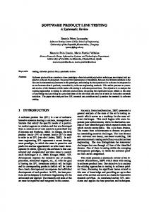
is presented in references [7] and [22]. The second part of this maturation was the definition of OOS archetypes. Archetypes are recurring patterns that define fundamental aspects of the system architecture [3]. Two main archetypes were embraced during the early stages of OneSAF development. The System, Product, and Component archetype shown in figure 1 explicitly represents the system level composability aspects so important to the three OneSAF user domains. OneSAF System Composition
The maturity levels defined shortly after A&I contract award provide a cornerstone for planning and measuring incremental progress. For OneSAF, the maturity levels are associated with interfaces that are defined in terms of an Application Programmer’s Interface (API), Data Interchange Format (DIF), or Graphical User Interfaces (GUI). The OOS maturity levels show progression as the interfaces move from lower to higher integration level. The five levels include [6]: 1.
OneSAF Product
Level 1: Component and interface types (API, DIF, GUI) described within the Product Line Architecture Specification
3.
Level 2: Three level 2 definitions are provided to account for API, DIF, and GUI types. For APIs, a level 2 provides a defined a usable software API with stubbed functionality. For GUIs, a level 2 describes a GUI mockup or screenshot showing screen layout and proposed functionality. For DIFs, a level 2 provides the XML-based DIF.
4.
Level 3: Level 3 builds upon level 2 and provides partial functionality behind the interface.
5.
Level 4: Level 4 provides full functionality of services supporting the interface.
Once these levels were established the requirements driven architecture and software development processes accelerated. The following two sections describe these coordinated parallel processes. 2.2.3
Requirements Driven Architecture Development
The A&I process started by maturing the government provided PLAF’s functional organization and clarity based on the ORD, TRD, and OCD requirements set. During this period a number of Products were added to the OOS Product Layer to support the OOS system lifecycle. Some Components were also moved to better align with their supported top-level Product. Finally a OOS Repository layer was added to highlight the significance of separating data from software [22]. This effort resulted in a better organized and clearer static, functional representation of the architecture. An indepth description of the static representation Product Line Architecture is beyond the scope of this paper but
OneSAF Product Layer
OneSAF Component Layer
OneSAF Component
Level 0: Interface not defined, system engineering necessary to define architecture component and interface to that component.
2.
OneSAF System Composition Layer
Figure 1: Composition-Product-Component OneSAF System Archetype [12] The second archetype, as shown in Figure 2, shows the Product to repository relationship archetype defining the fundamental relationships between OneSAF Products and their data and between external systems and their access to OneSAF data. • RDBMS-based development repository • File-based fielded repositories • Shared runtime repository (virtual DB)
• Pre-ex tools • Runtime tools and applications • Post-ex analysis tools
• Human monitoring and control • Constructive simulations • Manned simulators • C4I devices • Live range systems
OneSAF OneSAF Applications OneSAF Applications Products
OneSAF Repositories
External External Systems External Systems Systems
Figure 2: Product-Repository-External Archetype [12] During this period the architecture team also worked to enhance the organizing principles provided by the AIPT by providing authoritative reference information, adding additional principles, and prioritizing the final list of organizing principles. The resulting quality factors are used by the OneSAF system engineers and the architecture team to propose and implement tangible policies and software constructs supporting the abstract quality factors. The current list of architecture quality factors include [11]: •
Usability: “Usability is broken down into learnability (how quick and easy is it for a user to learn to use the system’s interface), efficiency (does the system respond with appropriate speed to a user’s requests), memorability (can the user remember how to do system operations between uses of the system), error avoidance (does the
system anticipate and prevent common user errors), error handling (does the system help the user recover from errors), and satisfaction (does the system make the user’s job easy).” [1, p. 81-82] •
Interoperability: “Interoperability measures the ability of a group of parts (constituting a system) to work with another system.” [1, p. 85]
•
Reliability and availability: Reliability is concerned with “component interaction during operation and the effects of component errors on the system reliability as a whole.” [3,p. 88]. “Availability measures the proportion of time the system is up and running.” [1, p. 80]
•
Maintainability: “Maintainability is the ability of a system to respond to requirements changes.” [3,p. 80]
•
Extensibility: The attribute is related to modifiability. Modifiability is “the ability to make changes quickly and cost effectively”. [1, p. 82]
•
Scalability: This attribute describes how well a system handles getting larger. Scalability is the ability to increase performance. “Performance refers to the responsiveness of the system – the time required to respond to stimuli (events) or the number of events processed in some interval of time”. [1, p. 79]
•
Portability: “The ability of the system to run under different computing environments”. [1, p. 83]
•
Flexibility/Composability: Describes how well a system can support a diverse set of architectural requirements.
•
Adaptability: Describes how easily a system can embrace a new approach or technology.
•
Integrability: “Integrability is the ability to make separately developed components of a system work correctly together.” [1, p. 84]
•
Security: “Security is a measure of the system’s ability to resist unauthorized attempts at usage and denial of service while still providing its services to legitimate users.” [1, p. 80]
•
Safety: “Safety is the concern of negative or even destructive effects the system under design may have on entities in the real world.” [3, p 88]
2.2.4
Bottoms-Up Software Development and Integration
In parallel and complementary with the Product Line Architecture definition the A&I team began software component development. The component development has been aligned with the Product Line Architecture and includes five development groups within the A&I: the modeling infrastructure group, the tools group, the simulation infrastructure group, the common services group, and the repository group. The majority of software is being developed in Java and initially
supports the Linux and Windows 2000 Operating systems. In the software development domain there is a documented natural tension between architecture definition and implementation, as implementations tend to creep away from the documented rules, policies, and constructs [4],[18]. The OOS answer to this tension is to iterate through the development cycle during Block A and mature and capture the viable system interfaces based on the lessons learned through software development. For Block A, there are eight build cycles, each eight weeks long. At the conclusion of each build cycle the software components are integrated and demonstrated within the OneSAF integration laboratory. The integration process is also fed with the legacy components selected for reuse. This approach appears similar to other development processes such as the Rapid Evolutionary and Exploratory Prototyping (REEP) process taken by the Distributed Mission Training Integrated Threat Environment System (DMTITE) to define and mature their software architecture [18]. The concept is to iteratively find and address specific issues early in the development cycle Within the OOS, the software is heavily influenced by a framework based development philosophy where future developers use and extend the basic software class structure and process flow. To illustrate dependencies between the various development groups a software architecture layering style [3] has been adopted. A draft of this diagram is shown in Figure 3. Products (Tools, Common & Comp. Services, C4I, KE Tools, Integration and Test) Components (Tools, Repositories, AAR, Common, Modeling Models Infrastructure, MSDE , KE Tools, C4I, EDGE) (Models, ERC, EDS) Modeling Services GUI Services Online Help (Modeling Infrastructure) (Tools) (Tools) Simulation Services (Infrastructure)
Runtime Database (Infrastructure)
MCG&I (ERC, Common & Composition Services)
Common Services Composition Services Exec. Builder Tool System Repository (Common & (Common & Services Comp. Services) Comp. Services) (Repositories) Platform (Common & Composition Services, Integration and Test, JDK, COTS hardware)
Figure 3: OneSAF Software Implementation Layers [13] This layering diagram depicts the dependencies of higher order software on lower layers. Lower layers are not allowed to use (depend) on services provided by higher layers. In the general OneSAF context, higher layers are allowed to access all lower layer services. As these parallel efforts drive forward, it is essential to the later Block development that they create a consistent picture of the OOS Product Line Architecture.
2.3 Summary Architecture definition, education, and management play a large role in the OOS development. To facilitate these communications driven processes web-based accessibility is provided to all architecture products to support ease of access and use. The two pronged approach for architectural development highlights the need for open architecture communication and education so that the resulting architecture products and software implementation are consistent, manageable, and extendable. By using this measured iterative approach to architectural development the OOS system will be poised to begin formal military modeling implementations in the Block B, 2003, timeframe. REFERENCES
9.
“OneSAF Mission approved May 1997.
Needs
Statement
10. “OneSAF Operational Requirements (ORD) Version 1.1”, 21 May 2001.
(MNS)”, Document
11. Courtemanche, Anthony. (2002) OneSAF Quality Attributes web page. 12. OneSAF Architecture Archetypes Presentation Dated February 12, 2002. 13. OneSAF Software Implementation Presentation Dated February 12, 2002.
Layers
14. STRICOM. (2000) “One Semi-Automated Forces (OneSAF) Technical Requirements Document (TRD)”, DOORS Electronic Information Environment, October 31, 2000. 15. STRICOM. (2000) “One Semi-Automated Forces (OneSAF) Operational Concept Document (OCD)”, DOORS Electronic Information Environment, October 31, 2000.
1.
Bass, Len; Clements, Paul; Kazman, Rick. (1998) Software Architecture in Practice, Addison-Wesley.
2.
Boehm, Barry. (2002) “Get Ready for Agile Methods, With Caution”, Computer, January 2002 Volume 35, pp 64-70.
16. STRICOM. (2000) “One Semi-Automated Forces (OneSAF) Reuse Direction and Guidance (RDG) DOORS Module”, DOORS Electronic Information Environment, October 31, 2000.
3.
Bosch, Jan. (2000) Design and Use of Software Architectures: Adopting and Evolving a Product-Line Approach. Addison-Wesley, 2000.
17. STRICOM. (2000) “One Semi-Automated Forces (One-SAF) Product Line Architecture Framework (PLAF)”, October 31, 2000.
4.
Brooks, Frederick. (1995) The Mythical Man-Month: Essays On Software Engineering. Addison Wesley Longman, Inc.
5.
Clemens, Paul; Northrop, Linda. (2002) Software Product Lines Practices and Patterns, Addison Wesley.
18. Stytz, M., R.; Banks, S.B. (2001) “The DMT Integrated Threat Environment System Architecture and Design”, ACM Transactions on Modeling and Computer Simulation, Vol. 11, No. 1, January 2001, Pages 106-133.
6. 7.
8.
Courtemanche, Anthony. (2001) “OneSAF PLAS Levels”, July 17, 2001 Courtemanche, Anthony; Wittman, Robert. (2002) “OneSAF: A Product Line Approach to a Next Generation CGF”, To appear as paper 079, 11th CGF Conference, May, 2002. Highsmith, Jim; Cockburn, Alistair: (2001) “Agile Software Development: The Business of Innovation”, Editor Barry Boehm, IEEE Computer September 2001, New Jersey
19. Sun Javadoc web http://java.sun.com/j2se/javadoc/
site.
20. World Wide Web Consortium. XML Schema Specification. http://www.w3c.org/XML/Schema 21. Wittman, Robert; Harrison, Cynthia. (2001) “OneSAF: A Product Line Approach to Simulation Development”, 01E-SIW-061, 2001. 22. Wittman, Robert; Harrison, Cynthia; Williams, Karen. (2002) “The OneSAF Objective System: Block A Development”, To appear as 02E-SIW-033, European Simulation Interoperability Workshop, June, 2002