The ORBIT Simulation Code: Benchmarking and Applications
Recommend Documents
was written in C and runs on PCs under MS DOS. This is a menu driven program with enhanced graphical capabilities. A UNIX version with off-line graphics and.
BENCHMARKING AND APPLICATION TO THE SNS EXTRACTION ... J. A. Holmes, V. Danilov, J. D. Galambos, ORNL/SNS, Oak Ridge, TN, 37831-6473, USA.
Index TermâBusiness process management system, public sector services ... characterized as the software applications that âenable the modeling, execution ...
Aug 31, 2007 - hosting hundreds to thousands of different applications1, analytical modeling for ..... agement are affordable in terms of cost, such as management of the .... Web services resource framework. http://www.globus.org/wsrf.
Han Solo name created_by acted_by. Character starring_in featuring featured_by. Fig. 2. A portion of IIMB 2010 performed manually by the designer, with the ...
efficient way to exploit the data parallelism hidden in ap- plications. ... The encoder also employs intra-frame analysi
from web sites using automatic extraction techniques, thus both data and links are not validated nor ..... challenge is to find the best - that means the narrowest - domain and range without turning the ... âcreated byâ â Character Creator.
ken line and parabolic approximations arc used. ORBIT includes six ... showed that it works reliably a11d is free from the utt- desirable effrct,s mentioned in the ...
Mar 15, 2010 - AbstractâWe provide an overview of the approach devel- oped by the Software Improvement Group (SIG) for code anal- ysis and quality ...
When a minimum level of software maintainability is reached, the certification body of TÃV Informationstechnik GmbH issues a Trusted Product ... Join for free ..... means that if a system is awarded 5 stars, it is comparable to the 5% best .... Base
Mar 15, 2010 - Email: [email protected] ... its calibration against a benchmark database of measure- ... C. The role of a software benchmark repository. Even with ...
improvement of the Romanian seismic design code and .... comparable processes in leading organizations ... the Romanian code, P100-1/2006, Eurocode 8.
the results of orbit simulation using a stochastic model to calculate the accuracy of .... We call this extended ephemeris the CGC 1 ephemeris (CGC: Center for ...
Abstract. Increasing market competition leads to a differentiation of service providers by offering hybrid services as value added services. In product- service ...
J. D. A. Smith, Tech-X UK Ltd., Daresbury, Chesire WA4 4FS, UK. Abstract. Multipacting is a potential limit on the power one can de- liver to different components ...
Oct 15, 2006 - the Scalable Synthetic Compact Applications (SSCA) benchmark suite, ..... application programmer to attain high performance on these codes.
Keywords: I/O Benchmarking, Data Intensive Applications, Access Patterns, POSIX .... We use the open source scanner tool Flex [12] to generate a fast and flexible ..... Skinner, D. Integrated Performance Monitoring of a Cosmology Application ...
The I/O benchmarking tools can easy this decision process. ... distributed widely if they reveal sensitive algorithms or data. ... parser layer provides grammar parsing of the token stream received from the scanner. .... Testing OLAP Engine I/O. The
Benchmarking for acoustic simulation software. A. R Molares and M.A. Sobreira-Seoane. University of Vigo, E.T.S.I de Telecomunicación, Rúa Maxwell s/n, ...
Benchmarking Reasoners for Multi-Ontology. Applications. Ameet N Chitnis, Abir Qasem and Jeff Heflin. Lehigh University, 19 Memorial Drive West, Bethlehem, ...
[18] Rakesh K Yadav, Mahendra K Verma and Pankaj Wahi, Phys. Rev. ... [19] Hirdesh K Pharasi, Rahul Kannan, Krishna Kumar and Jayanta K Bhattacharjee,.
Androidâthis trend seems to be gaining ... Android, to name twoâallow users to scan a barcode on a ... coupon or discount; 72 percent were more likely to ...
The ASCOT code follows charged test particles in a fully 3D magnetic field. .... 108. 1010. 1012. #19913 @2.65 s. Energy (keV). Neutral flux (s ster eV m. 2 )−1.
the third planet after mercury and Venus from the ... The Earth orbit is the motion of Earth around Sun ... massive body due to gravity. ... major axis a: the ratio T. 2.
The ORBIT Simulation Code: Benchmarking and Applications
benchmarking and the current usage of the ORBIT code are presented. INTRODUCTION ... Alamos Neutron Science Center (LANSCE), USA. PSR has accumulated a .... This is the reason we call the model 2.5D. There is also an alternative ...
Proceedings of ICAP 2006, Chamonix, France
MOA2IS01
THE ORBIT SIMULATION CODE: BENCHMARKING AND APPLICATIONS* A. Shishlo#, S. Cousineau, V. Danilov, J. Galambos, S. Henderson, J. Holmes, M. Plum, ORNL, Oak Ridge, TN 37831, U.S.A. Abstract This work describes the purpose, content, structure, benchmarking, and applications of the ORBIT code. ORBIT is a multi-physics parallel computer code designed for the realistic simulation of processes in accelerators. Physics approaches, algorithms, and limitations for space charge, impedances, and electron cloud simulations are discussed. ORBIT has a long history of benchmarking with analytic exactly solvable problems and with experimental data. The results of this benchmarking and the current usage of the ORBIT code are presented.
“script” input file without any new compilation. These script input files are extended SuperCode programs without any predefined set of logic to do a run. Additionally, routines can be created on-the-fly in script files and included in the customized run sequence. The SuperCode programming language is very close to C, and it should not be difficult to use for physicists.
INTRODUCTION ORBIT (Objective Ring Beam Injection and Tracking) began as an “in house” accelerator code for the Spallation Neutron Source (SNS) project in 1997 [1]. SNS is the world’s most intense pulsed neutron source and is characterized by low energy, high intensity, and low loss requirements. To satisfy the beam-loss requirements a detailed understanding of beam dynamics in this regime is a necessity. The single particle dynamics is not sufficient to describe the physics of the SNS accelerator ring due to the high intensity of the beam. From the beginning, ORBIT was designed to accommodate an expandable set of collective effects models such as space charge and wakefields. Also, ORBIT has been designed to simulate real machines: it has detailed models for transport through various lattice elements; injection foil and painting; rfcavities and acceleration; apertures; collimation; and beam diagnostics. In this work we concentrate on ORBIT modules that simulate collective phenomena for bunched beams in high-intensity rings: impedances, space charge, and electron cloud modules. The place of these modules in the ORBIT programming structure, algorithms, implementations, and benchmarking results are discussed.
ORBIT CODE STRUCTURE The ORBIT code is written in C++, and operates using the SUPERCODE [2] driver shell (see Fig. 1). SUPERCODE combines an interpreter of the SuperCode programming language, a wrapper generator, and several utilities modules implemented in C++. ORBIT adds physics modules with SuperCode interfaces to SUPERCODE, and therefore it extends the SuperCode programming language with accelerator physics commands. Generally, runs are done by reading in a ____________________________________________
* ORNL/SNS is managed by UT-Battelle, LLC, for the U.S. Department of Energy under contract DE-AC05-00OR22725 # [email protected]
Computer Modeling of High Current Effects Circular Accelerators
Figure 1: The ORBIT code structure as an extended Super Code Interpreter. From the physics point of view, the ORBIT code is a PIC (particle-in-cell) code that tracks macro-particle coordinates through a set of accelerator elements. This set of elements is represented by a C++ array of references to instances of the ORBIT Node class or its subclasses. New physics can be easily implemented by creating a subclass of this base Node class and interfacing it to the Super Code script level. The composition of an accelerator lattice is defined in the driver shell script file. Usually the lattice includes single particle tracking nodes and collective physics and diagnostics nodes between them. That flexible structure of the ORBIT code allowed successful development for many years and an independent participation of several developers.
BENCHMARKING We are going to present results of several benchmarking techniques and their combinations for the ORBIT code: comparison between two computer codes; comparison between simulation and analytic results; and comparison between simulation and real experimental data. The first approach when two codes are used for the same physical problem is very useful in the case of inheritance of a specific algorithm by one code. The second approach is widely used as a debugging tool. The benchmarking with experimental data is the most comprehensive test of models, because it usually requires the use of several modules at the same time to realistically reproduce the existing situation and processes. There are a lot of similarities between the SNS accelerator and the Proton Storage Ring (PSR) at the Los
53
MOA2IS01
Proceedings of ICAP 2006, Chamonix, France
Alamos Neutron Science Center (LANSCE), USA. PSR has accumulated a large amount of experimental data during many years of operation. Therefore, PSR data are a natural source for benchmarking the ORBIT code before SNS will be fully operational. Most our benchmarks of experimental data are related to PSR.
LONGITUDINAL IMPEDANCE AND LONGITUDINAL SPACE CHARGE ORBIT treats longitudinal impedances and/or space charge in a fashion similar to ESME code [3]. The longitudinal impedance is represented as harmonics of the fundamental ring frequency. Particles are binned longitudinally and the binned distribution is Fourier transformed. The finite number of harmonics used for the Fast Fourier Transformation (FFT) acts as a low-pass filter that mitigates spurious emittance growth due to local fluctuations. The longitudinal space charge contribution to the impedance is combined with the external user defined impedance. The Fourier transformed distribution is multiplied by the impedance to give the longitudinal kicks to the particles. For many rings, the synchrotron period is much longer than a turn, and it is sufficient to evaluate the longitudinal impedance and space charge kicks once each turn. More frequent evaluations may be required for rings having higher synchrotron frequencies. This ORBIT module was successfully benchmarked against the ancestor ESME code and experimental data from PSR showing long-lived linac micro-bunch structure during beam storage with no ring rf bunching. Analysis of the experimental data and particle-in-cell ORBIT simulations of the experiments indicated that longitudinal space charge, coupled with energy spread effects, is responsible for the sustained micro-bunch structure [4].
TRANSVERSE IMPEDANCE MODULES There are two transverse impedance modules in the ORBIT code. The first is based on a frequency domain representation, and the second uses a simple resonance structure in the time domain. These modules are completely independent. The physical approaches implemented in these modules are different, but results of simulations for the same problems agree well.
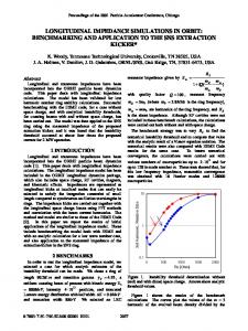
an evolution of a coasting beam with Lorentz energy distribution in a constant focusing storage ring with single harmonic impedance. The stability threshold in intensity of the beam has been predicted within 5%. The halo growth for intensities below the threshold has also been successfully reproduced by the model. Figure 2 shows the vertical phase space of one short longitudinal slice. One can see that the simulation preserves even small details of an analytic solution, showing the ability of the code to give accurate results.
Figure 2: Phase space after 50 turns. Numerical solution on the left shows a group of particles within a short slice. The analytic solution (right) represents an infinitely thin slice and is therefore less fuzzy.
Time Domain Module This module uses a wake field of the local element in the lattice to calculate the transverse force kick for each particle in the bunch [6, p.58, formula 2.50].
where F is the force integrated over the length of the element; j1 is the line density of the first moment of the bunch; and
W1 is the wake function of the element.
Frequency Domain Module This module implements the same FFT approach as the longitudinal impedance module. The complication is that the betatron motion has a much higher frequency and the harmonics of the dipole current consist of the betatron sidebands of the revolution harmonics. Also, the number of transverse dimensions is two. Therefore the transverse impedance requires four times as many arrays and calculations as the longitudinal impedance. The detailed description of the algorithm of this module can be found in the PAC’01 paper [5]. The benchmark of this module has been performed as a comparison between results of simulations and an exactly solvable case of beam dynamics [5]. The case considers
54
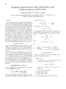
Figure 3: The transverse momentum kick vs. particle position in the bunch after 4 previous passages through the lattice element. The wake function should satisfy a phasor condition [6]. In this case the effective numerical integration in the formula (1) could be performed over all previous bunch passages through this lattice element. The simplest example of such a function is an RLC resonant element. For this module in ORBIT, the user can specify a
Computer Modeling of High Current Effects Circular Accelerators
Proceedings of ICAP 2006, Chamonix, France
transverse impedance element as a sum of any number of RLC elements. Fig. 3 shows identical results from ORBIT simulations and from analytic calculations for the transverse kick gained by particles in the bunch after multiple passages through the same lattice element with non-zero transverse impedance.
2.5D AND 3D SPACE CHARGE MODULES Space charge effects are an important factor in determining beam profiles, instabilities and halo generation in high intensity, low-energy storage rings, such as SNS, and in synchrotrons. ORBIT includes two modules to simulate the space charge force in long bunches. The 2.5D Space Charge module uses a simplified approach, but it is far less demanding with respect to computer resources than the 3D Space Charge module. In both modules the algorithms are based on the assumption that the length of the bunch is significantly greater then the transverse size of the beam and the beam pipe diameter.
2.5D Space Charge Module The 2.5D space charge model is implemented as a series of transverse momentum kicks separated by other transport operations on the lattice elements. Particles are binned in a 2D rectangular grid using a second order distribution scheme. The potential for the distributed charges is then solved on the transverse grid using a fast FFT solver. Conducting wall (circular, elliptical, or rectangular beam pipe) boundary conditions are then imposed using a method described in Ref. [7]. Particle kicks are obtained from second order interpolation of the potential, completing what might be called a “quasisymplectic” evaluation. Finally, the kicks are weighted by the local longitudinal density to account for bunch factor effects. This is the reason we call the model 2.5D. There is also an alternative direct force (momentum-conserving) solver without beam pipe that is used mostly for debugging and internal benchmarking purposes. This module has been successfully used to explain the beam transverse distribution in the PSR ring [8].
MOA2IS01
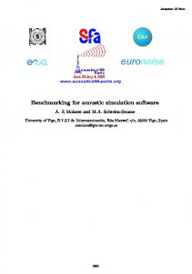
charge module. For self-consistency, it is necessary to use this module together with transverse impedance modules. At the same time, simulations with this module require a multiple CPU computer or parallel cluster, because the number of particles and grid points are proportional to the number of transverse slices in the 3D grid. Figure 4 demonstrates the agreement between the two space charge modules for the special case of a triangular longitudinal density distribution of the bunch [9].
Figure 4: 3D space charge benchmark for triangular charge distribution: a) tune shifts vs. position, b) longitudinal force vs. position. 2.5D and 3D results agree with each other and with analytic calculations [9].
ELECTRON CLOUD MODULE The instability caused by an electron cloud effect (ECE) may set an upper limit to the intensity of proton storage rings. This type of instability has been observed in PSR for many years, and it has already been seen at SNS. The electron cloud module of the ORBIT code includes self consistent dynamics of the proton beam and the electrons including both their space charge interactions and their motion in external electric and magnetic fields. It also has a realistic surface model describing elastic and inelastic interactions of electrons with the beam pipe. In the ORBIT ECE simulation algorithm the ring is covered by a set of Electron Cloud Nodes (ECN). Each node is independent from the others, and calculates momentum kicks induced by the electron cloud and applies these kicks to particles in the bunch. More ECNs means more realistic simulations, but the calculation time becomes a limiting factor.
3D Space Charge Module The 3D space charge model is a simple generalization of the 2.5D routine. Particles are distributed to a 3D rectangular grid using a second order scheme. Typically, for rings, the longitudinal spacing greatly exceeds the transverse spacing. The potential is solved as a 2D problem using the distributed charges and fast Fourier transforms on the transverse grid for each longitudinal slice. Conducting wall boundary conditions (circular, elliptical, or rectangular beam pipe) are used to “tie together” the transverse solutions into a 3D potential. Particle kicks are obtained by interpolating the potentials in 3D using a second order “quasi-symplectic” interpolation scheme. In this model the transverse distribution and the mass center position of the bunch vary in the longitudinal coordinate, unlike the 2.5D space Computer Modeling of High Current Effects Circular Accelerators
Figure 5: ORBIT’s electron cloud module structure.
Electron Cloud Module Structure The general structure of the EC module and its fit into the ORBIT code are shown in Fig. 5. The new module is
55
MOA2IS01
Proceedings of ICAP 2006, Chamonix, France
mostly independent from the original ORBIT code and can be used either inside other accelerator codes or by itself. The ECloud class is merely a SuperCode wrapper of the EP_Node and EP_NodeCalculator class methods. These classes interact with structures and classes of original ORBIT and organize the whole EC simulation process. The details of the EC module implementation have been discussed in Ref. [10].
Electron Cloud Physical Model In each ECN the simulated physical system consists of the proton bunch, electrons inside a special region that is called an electron cloud region, and a perfectly conducting pipe whose surface can be a source of primary or secondary electrons (see Fig. 6). The protons propagate around the ring using ORBIT, with location s as independent variable, until they encounter an electron cloud region. At this time, they are frozen and passed through the electron cloud region where they contribute to the electron dynamics, which is calculated using time as the independent variable. The time step is chosen small enough to provide numerical convergence of the results. During each time step the analytic solution of equations of motion in uniform electromagnetic fields is used for the electrons. The changes in proton momentum due to the electron cloud are accumulated as kicks in an auxiliary grid covering the proton beam and applied to protons by interpolation at the end of propagation through the electron cloud region.
Figure 6: Simulated physical system for the Electron Cloud Node in ORBIT. For both electrons and protons the PIC method is used to calculate fields, so subsidiary grids are needed for space charge densities and potentials. The proton bunch is assumed to be longer than its transverse size. Hence, the 3D grids are treated as a set of transverse 2D grids uniformly distributed along the longitudinal coordinate. For each 2D slice, an independent space charge problem is solved and this provides an opportunity for effective and simple parallelization of the code. This approach is applicable for long and thin bunches. These simplifications are completely reasonable for both SNS and PSR. The length of each ECN should be short enough to ignore changes in Twiss parameters inside. Each region has its own bunch of electrons with its own unique history and dynamics, and a set of external magnetic fields if we 56
consider EC inside magnets. Interaction between the different electron clouds region exists only through the proton beam dynamics. The limited length of each ECN creates a technical problem with the electron cloud simulation time. If we cover the whole ring with ECNs the time needed will be unrealistic. To simplify the problem we introduced an effective length of the Electron Cloud Node in ORBIT. Actions of the electron cloud on the protons in each longitudinal slice of the bunch are taken into account by applying a momentum kick to every proton in the slice (2) 'p ( Leff / Lec ) e E ec (t ) 't where Lec is the length of the EC Node, E ec is an electric field created by EC, 't is the time of motion of the proton through this EC region, and Leff is an effective length for the EC node. With the effective length, the complete set of ECNs can be replaced by one or a few nodes with effective lengths set to represent coherent action from electron clouds populating the entire ring. This is an unrealistic approach (it gives an overestimation of the electron cloud action on the proton bunch), but it provides a very conservative estimate of the stability limit. Of course, if we want to be close to reality we have to use as many ECNs as possible.
Surface Model The secondary electron emission processes on the beam pipe surface are simulated by using a modified model of Furman and Pivi [11]. We altered the Monte Carlo scheme of Ref. [11] to save calculation time. The basic feature of the change is to remove the electron-macro-particle hitting the surface from the electron bunch and to add new electron macro-particles with a total macrosize multiplied by the secondary emission yield (SEY), compared to the macrosize of the removed electron-macro-particle, and with their energy determined by sampling from the model spectrum. The number of new macro-electrons is a variable defined dynamically to maintain a certain number of electrons in the cloud. This Monte Carlo scheme controls the number of macro-particles and their macrosize without changing the physics of the model. As our benchmark of the surface emission model, we calculated the secondary electron energy spectra from normal incident electrons on copper and stainless steel surfaces and compared the ORBIT results with those of Furman and Pivi.
Electron Cloud Module Benchmark against Analytic Two-Stream Model To benchmark ORBIT, the EC module for an analytically solvable two-stream model [12] has been used. The model considers a ring filled with two uniform circular bunches with opposite charges. One of bunches is moving along the ring, which is an accelerator lattice with constant focusing. The two bunches interact electromagnetically. The analysis in Ref. [12] shows that the system can be unstable with regard to transverse
Computer Modeling of High Current Effects Circular Accelerators
Proceedings of ICAP 2006, Chamonix, France
oscillations of bunches. Parameters of the model have been chosen close to the SNS case with nominal proton bunch density and size. To save simulation time only 1/178 part of the SNS ring length has been used. This means that we considered only one wavelength of the dipole instability oscillations. Twenty ECNs were used to cover this part of the ring. The development of the instability has been simulated for different values of the neutralization factor (2) K U /U
e
MOA2IS01
x The relationship between the maximum number of protons in the bunch and the threshold rf voltage. Figure 8 shows that development of the proton bunch instability causes the intensification of the electron production and vise versa. The same effect has been observed in PSR.
p
which is the ratio of electron cloud and proton bunch densities. For the small values of K (several percent) the ratio between the electron and proton oscillation amplitudes is on the order of one hundred. Small oscillations of the proton bunch are accompanied by significant electron cloud oscillations, which destroy the basic assumption of the model about the uniform covering of the proton bunch by the electron cloud. Therefore, we can not expect exact agreement between the analytic model and the simulation results. A detailed analysis of this benchmark can be found in Ref. [13]. Figure 7 shows the instability growth rate as a function of the neutralization factor for the two-stream model.
Figure 8: Instability development for one ECN in the PSR lattice. The left half is the simulation results, and the right half is the real PSR data. The Fig. 9 demonstrates the effect of placing the ECNs inside the dipole magnets to cover the whole range of vertical beta functions. Before this modification, the simulations showed instabilities in both vertical and horizontal planes. The growth rate of the horizontal oscillations sometimes was bigger than the rate in the vertical plane. After taking into account the electron cloud in the dipole magnets we have reversed this situation. This effect can be explained by the fact that electrons inside the dipoles move primarily along the vertical magnetic field, so the horizontal oscillations of the electrons are suppressed.
Figure 7: Computational and theoretical growth rates versus neutralization factor [13].
Electron Cloud Module Benchmark against PSR Data The purpose of this benchmark [14] was to demonstrate that the ORBIT code with the electron-cloud (EC) module can reproduce the main features of electron-cloud driven instabilities in a real machine, namely in the Los Alamos Proton Storage Ring [15]. The benchmark was focused on a limited number of the PSR instability features because of the high computational cost of each simulation. In particular, the following has been demonstrated: x Existence of the instability. x The coupling between proton instabilities and electron production. An intense electron flux coincides with high amplitude coherent proton bunch oscillations at the onset of substantial beam losses. x Agreement with the observed frequency spectrum of the proton bunch oscillation. x An asymmetry in directions where instabilities occur. The instabilities have been seen mostly in the vertical direction.
Computer Modeling of High Current Effects Circular Accelerators
Figure 9: Effect on instabilities in both planes when the ECNs inserted into dipole magnets The use of realistic distribution of several ECNs in the lattice also predicts the correct frequency of the proton bunch vertical oscillations. In practice, the electron-cloud-related instabilities in the PSR ring are controlled by increasing the voltage to the rf cavities. The higher rf buncher voltage leads to a larger energy spread in the proton bunch. The experimental data show that the maximum stable charge of the proton bunch scales linearly with the rf voltage. A set of simulations was carried out in an attempt to reproduce this dependence. We ran simulations for 3.2 and for 6.4 ȝC bunches at several values of the rf voltage. For all runs, a lattice with 7 distributed ECNs was used. The results of simulations with different rf voltage values are shown in Fig. 10. They clearly demonstrate that instabilities can be suppressed by applying a sufficient rf voltage. Also, with increasing voltage the growth time of 57
MOA2IS01
Proceedings of ICAP 2006, Chamonix, France
instabilities increases from tens to hundreds of turns. These numbers are in good agreement with experimental results.
Figure 10: The time evolution of average amplitudes of the vertical proton beam oscillations. (a) 3.2 ȝC and (b) 6.4 ȝC cases.
CONCLUSIONS Many successful benchmarking results have demonstrated that the ORBIT code can be successfully used for the realistic simulation of collective effects in accumulator rings. These effects include impedances, space charge, and electron clouds. The flexible structure of the code allows combining these effects in user defined configurations, and it presents the possibility of further development of ORBIT.
ACKNOWLEDGEMENT This research used resources of the National Energy Research Scientific Computing Center (NERSC), which is supported by the Office of Science of the U.S. Department of Energy under Contract No. DE-AC0376SF00098.
REFERENCES [1] J. A. Holmes, S. Cousineau, V.V. Danilov, J. Galambos, A. Shishlo, W. Chou, L. Michelotti, F. Ostiguy, and J. Wei, in Proceedings of the 20th ICFA Advanced Beam Dynamics Workshop on High Intensity and High Brightness Hadron Beams, Fermilab, 2002 (AIP, Melville, NY, 2002); J. A. Holmes, S. Cousineau, V.V. Danilov, S. Henderson, A. Shishlo, Y. Sato, W. Chou, L. Michelotti, and F. Ostiguy, in The ICFA Beam Dynamics Newsletter, Vol. 30, 2003.
58
[2] Haney, S.W., “Using and Programming the SUPERCODE”, UCRL-ID-118982, Oct. 24, 1994. [3] J. A. MacLachlan, Longitudinal “Phase Space Tracking with Space Charge and Wall Coupling Impedance,” Fermi National Accelerator Laboratory, FN-446, (1987). [4] S. Cousineau,V. Danilov, and J. Holmes, Phys. Rev. ST Accel. Beams 7, 094201 (2004). [5] V.Danilov, J. Galambos, J. Holmes,, “Transverse Impedance Implementation in ORBIT,” PAC’01, Chicago, IL, June 2001, p. 1752 [6] A. W. Chao, “Physics of Collective Beam Instabilities in High Energy Accelerators,” Wiley, New York, 1993. [7] F. W. Jones, “A Method for Incorporating Image Forces in Multiparticle Tracking with Space Charge,” EPAC 2000, Vienna, p. 1381. [8] J. D. Galambos, S. Danilov, D. Jeon, J. A. Holmes, and D. K. Olsen, Phys. Rev. ST Accel. Beams 3, 034201 (2000) [9] J.A. Holmes, V. Danilov, J. Galambos, A. Shishlo, S. Cousineau, W. Chou, L. Michelotti, F. Ostiguy, J. Wei, “Orbit: Beam Dynamics Calculations For HighIntensity Ring,” EPAC’02, Paris, June 2002, p. 1022 [10] A. Shishlo, Y. Sato, J. Holmes, S. Danilov, S. Henderson,, “Electron-Cloud Module for the ORBIT Code,” in Proceedings of the 20th ICFA Advanced Beam Dynamics Workshop on Electron Cloud Effects ECLOUD’04 (Napa, CA, USA April 2004), p. 241. [11] M.A. Furman and M.T.F. Pivi, Phys. Rev. ST Accel. Beams 5, 124404 (2002). [12] D. Neuffer, E. Colton, D. Fitzgerald, T. Hardek, R. Hutson, R. Macek, M. Plum, H. Thiessen and T.S. Wang, NIM A321, 1-12 (1992). [13] Y. Sato, A. Shishlo, S. Danilov, J. Holmes, S. Henderson,, “Simulation of E-Cloud Using Orbit: Benchmarks and First Application,” in Proceedings of the 20th ICFA Advanced Beam Dynamics Workshop on Electron Cloud Effects ECLOUD’04 (Napa, CA, USA April 2004), p. 245. [14] A. Shishlo, Y. Sato, S. Cousineau, V. Danilov, S. Henderson, J. Holmes, R. Macek, S.Y. Lee, “SelfConsistent Electron-Cloud Simulation for Long Proton Bunches,” PAC’05, Knoxville, TN 2005, p.722 [15] R. Macek, et al, “Electron proton two-stream instability,” PAC’01, Chicago, June 2001, p. 688.
Computer Modeling of High Current Effects Circular Accelerators